For this wildcard week, I decided to fabricate a series of recognition plaques inspired by the Afro-Panamanian culture, which is an important part of Panama’s cultural identity and heritage. The fabrication process combines laser cutting techniques with UV flatbed printing technology.
The UV flatbed printer is capable of printing directly onto rigid materials such as acrylic, MDF, wood, and other flat surfaces. This process allows high-quality full-color graphics to be applied directly onto the material without the need for adhesive vinyl or transfer paper.
To begin the fabrication workflow, I first developed the 2D design using Adobe Illustrator. The design stage focused on organizing the artwork according to the printing requirements of the UV flatbed machine.
Below is a short video showing part of the 2D design process.
As shown in the video, the design is organized into multiple layers because the UV flatbed printer works using a layered printing process. First, the machine applies a white ink base layer onto the material surface, followed by the color layer.
This white base layer is especially important when printing on transparent or dark materials because it improves color visibility and contrast. Without this layer, the printed colors would lose brightness and detail due to the material background.
For the printing workflow, two separate image files are required. The first file contains the white ink layer, while the second file contains the full-color artwork. Both files must be properly aligned to ensure accurate registration during the printing process.
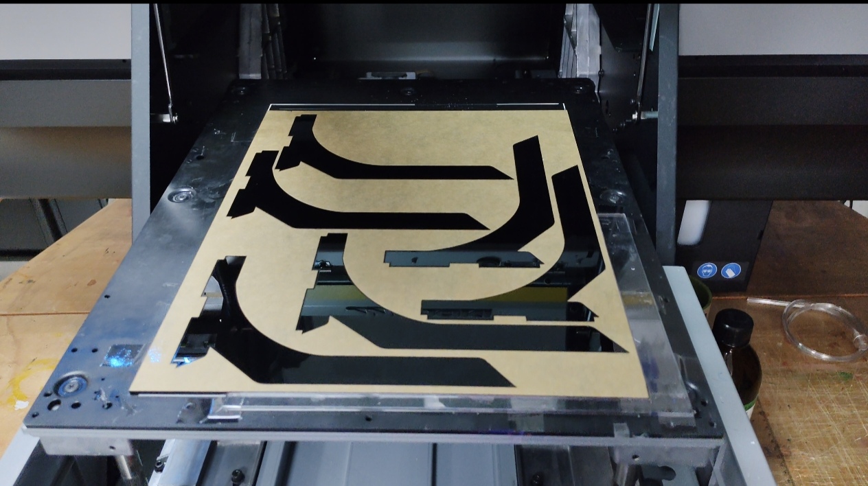
To achieve accurate printing over complex geometries, it was necessary to fabricate a positioning template. This template ensures that each piece is placed consistently inside the UV flatbed printer, improving alignment precision during the printing process.
The template was manufactured using laser cutting technology. During the same process, the acrylic parts where the full-color graphics would later be printed were also cut, as shown in the following video.
As observed in the video, after organizing the design files and preparing the cutting layout, the workflow moved to the laser cutting stage. At this point, both the positioning template and the acrylic geometries for the final printed pieces were fabricated.
The same laser cutting machine previously documented during Week 3 was used for this process.
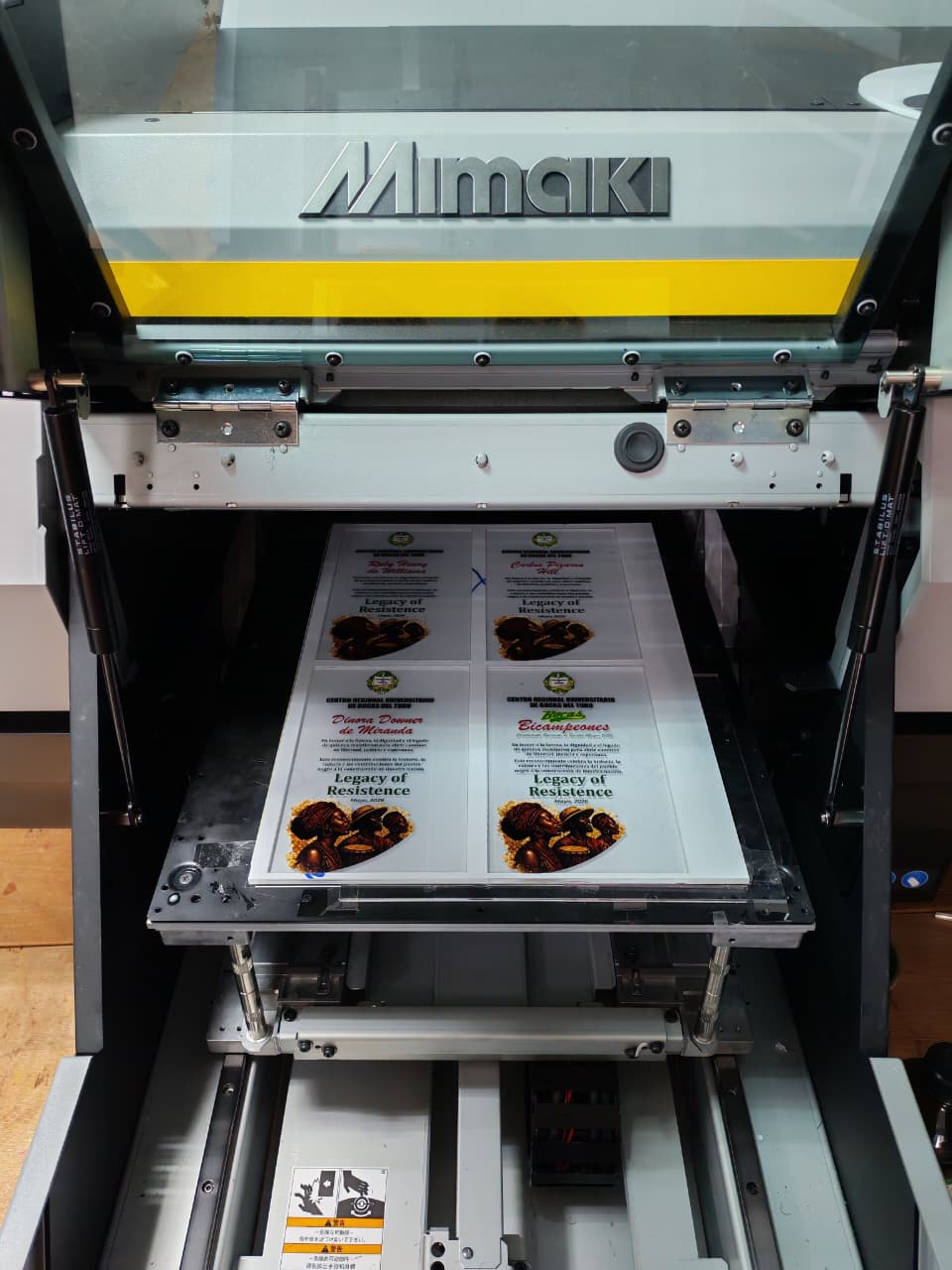
Once all the components were cut, the next step was preparing the UV flatbed printer for the printing process. The machine used for this fabrication stage is shown below.
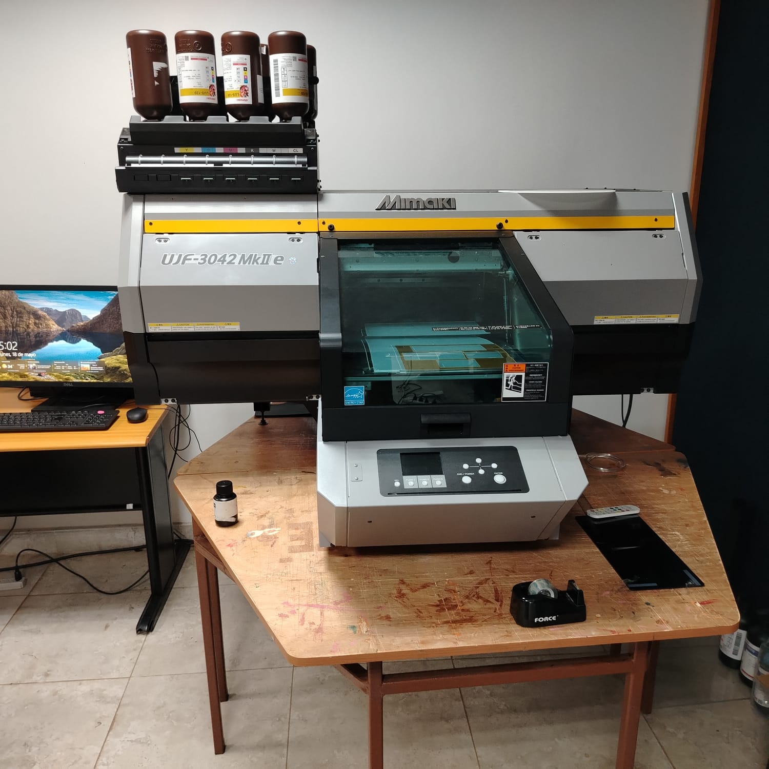
Mimaki UJF-3042 MkII e UV flatbed printer
The next step consisted of launching the RasterLink 7 software, which is used to configure and manage the printing workflow.
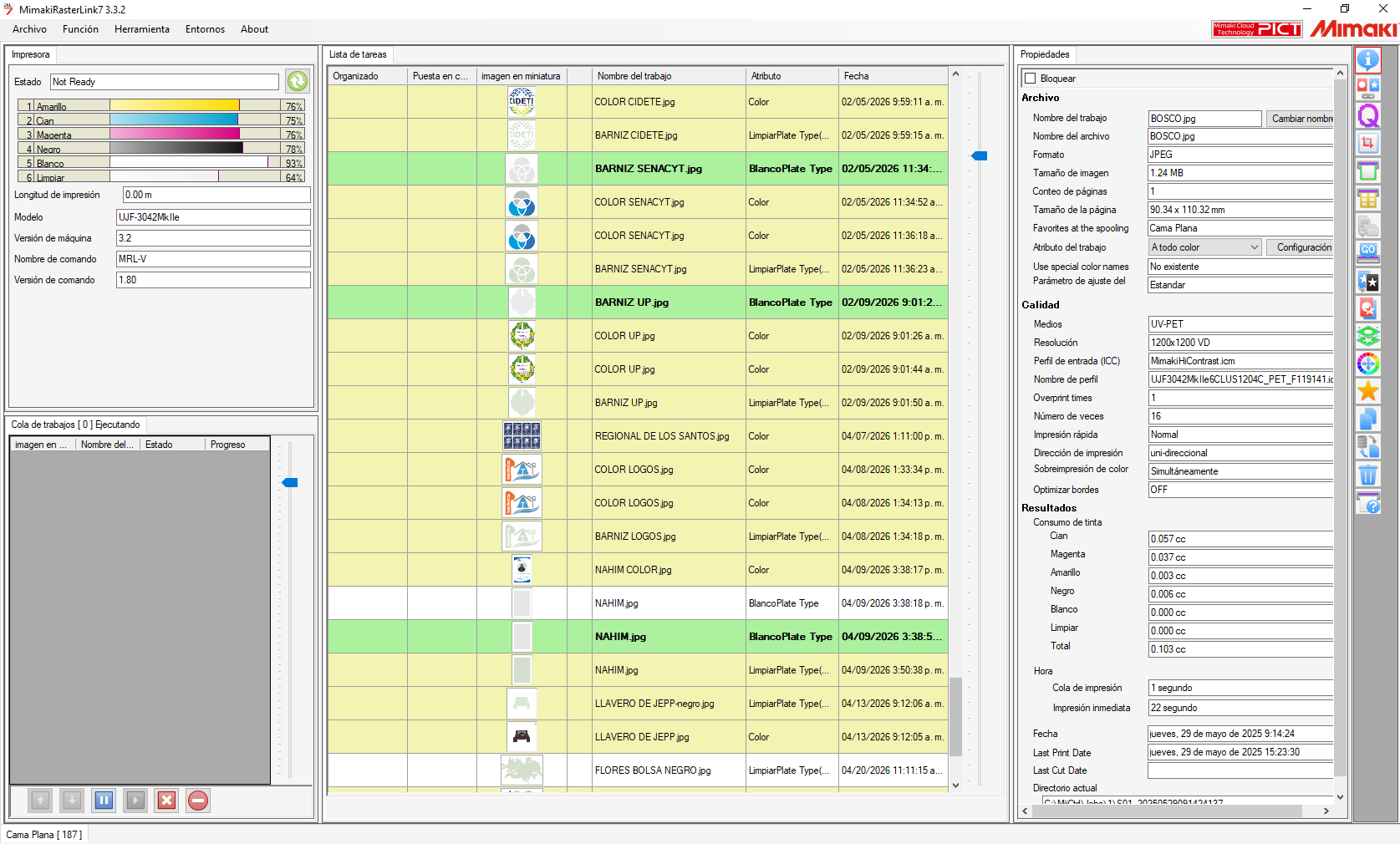
The following image shows the user interface of the Mimaki RasterLink software, which is used to prepare and manage print jobs for the UV flatbed printer. This software acts as the communication bridge between the digital design files and the printing machine.
The interface is divided into several functional sections that allow monitoring of the printer status, management of print queues, and configuration of printing parameters. On the left side of the interface, the software displays the current printer status, including ink levels for each color channel such as cyan, magenta, yellow, black, white, and varnish.
In the central area, the program displays the print queue, where imported files are organized with thumbnails, print attributes, and timestamps. Different printing layers such as color, white ink, and varnish can be managed independently.
On the right side of the interface, detailed printing properties are available, including resolution, media type, print direction, color profiles, and estimated ink consumption. These settings are important for optimizing print quality according to the selected material.
After reviewing the software interface, the machine configuration process begins. The working origin is first established at X = 0 and Y = 0. The Z-axis height must then be adjusted according to the material thickness.
For example, if the material thickness is 6 mm, the printing height is configured slightly above the surface, approximately at 6.5 mm, to prevent contact between the print head and the material.
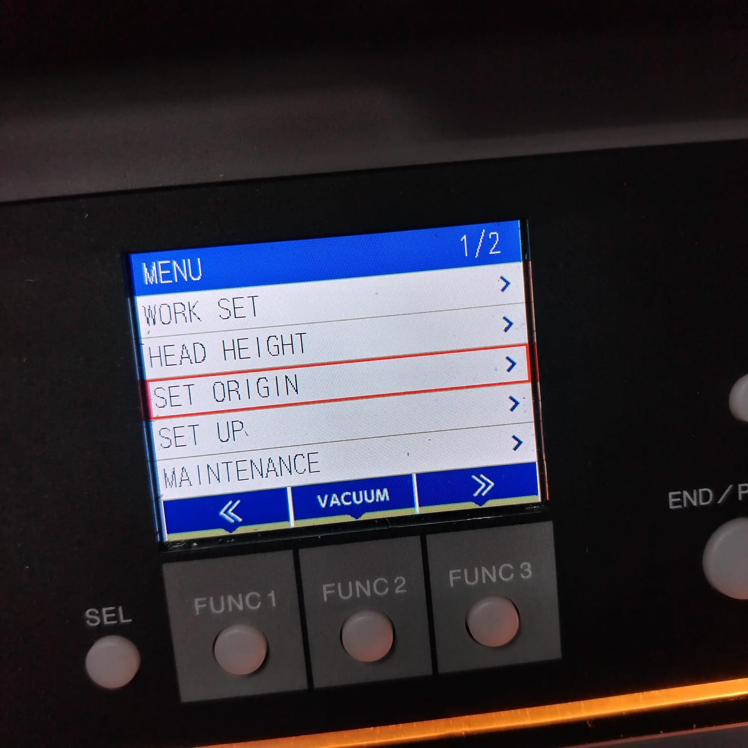
Configuring the material thickness and printing height
Once the machine configuration was completed, the previously laser-cut positioning template was placed onto the printer bed before starting the printing process.
As shown in the video, the UV printer progressively applies the graphic onto the acrylic surface while simultaneously curing the ink using integrated ultraviolet light. This curing process allows the ink to dry instantly during printing.
The next stage of the workflow involved the assembly process. The following tools were used for assembling the final pieces.
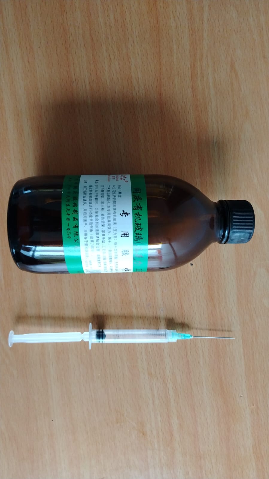
The bottle shown in the image contains acrylic cement, which is specifically designed for bonding acrylic components. A syringe was used to apply the adhesive with greater precision.
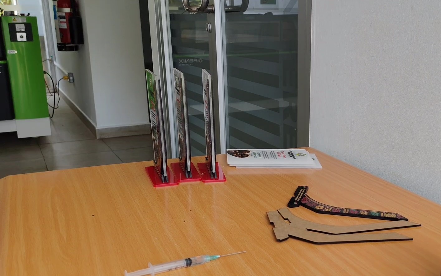
The assembly process consists of placing the transparent acrylic layer over the printed component in a sandwich-like structure, as shown in the image above. The final assembled piece is then attached to its red acrylic base.
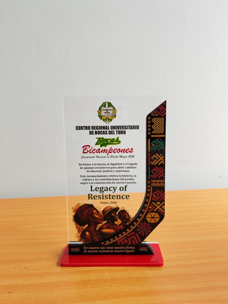
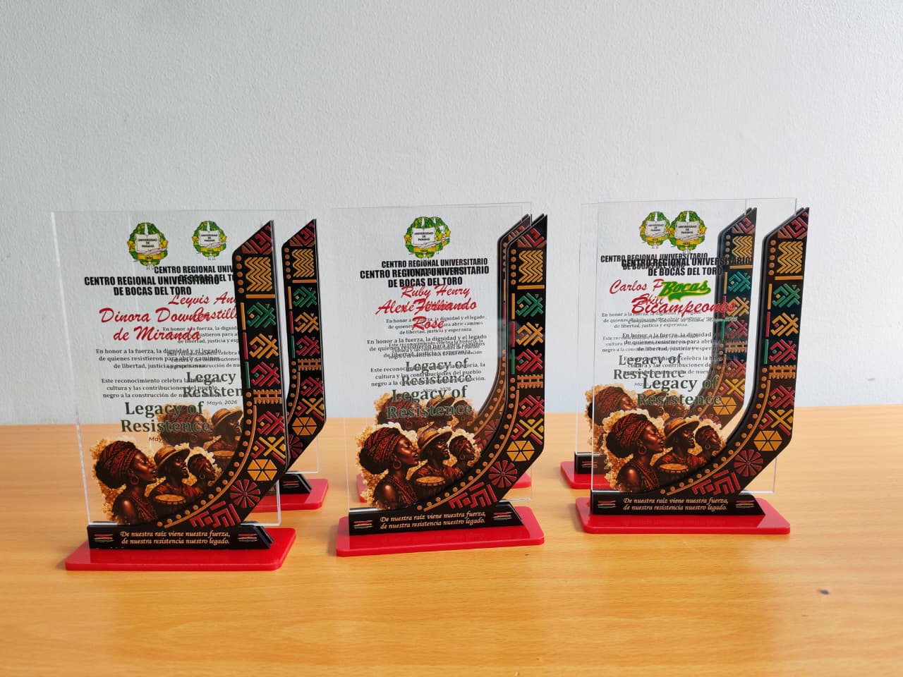
Final result.
Downloads

Here you can download my dising file