11. Networking and communications
Group AssignementThis week I learned (for the first time ever) how to communicate between microcontrolers and devices. Or how it can be done through many different options.
Some of of the things to consider before deciding on a communication channel:
- What hardware will you be using? And what are it's specifications and capacities?
- How fast is the exchange of information needed?
- How much information will be exchanged?
- How many devices will be communicating?
- Is a local or public network needed? (Careful with credentials and regulations)
- Will a visual interface be needed?
- Will the system change along the way? (Will devices will be added or removed?)
- How far does the information have to travel?
To start, I chatted a little with ChatGPT about the idea I had, the specificaitions of the boards I would be using and my vision to scale this assignement to my final project:
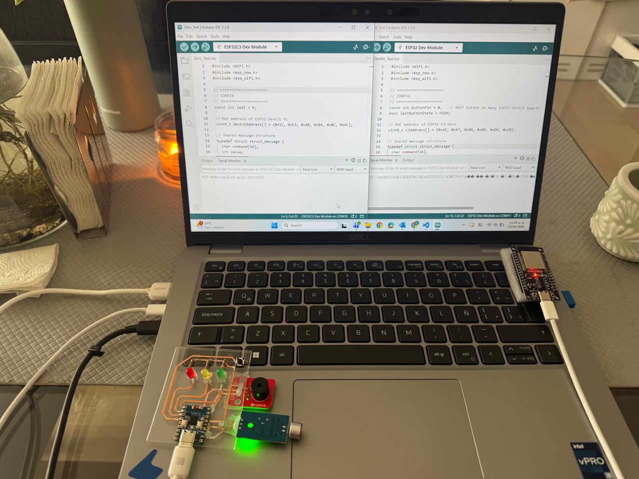
My initial question - I wanted to connect two boards: an ESP32-C3-Zero (with LEDs, buzzer, and microphone), and an ESP32 DevKit V1 (as controller).
The goal: Pressing a button on the DevKit triggers the LED + buzzer pattern on the C3, while the C3 keeps reading the microphone, and the DevKit receives that signal and prints a message in Serial.
I also asked which communication method would work best and how this could scale to my final project.
Chat's recommended solution: The best option is ESP-NOW, a direct, low-latency wireless protocol between ESP32 boards that does not require Wi-Fi infrastructure.
Why ESP-NOW:
- Simple and fast for device-to-device control
- No router needed (ideal for installations and demos)
- Lower complexity than BLE or HTTP servers
- Scales well to multiple nodes for the final project
Proposed architecture:
ESP32 DevKit V1 (Host / Controller)
- Uses BOOT button (GPIO0)
- Sends TRIGGER command
- Receives SOUND events and prints to Serial
ESP32-C3-Zero (Remote Node)
- Executes LED + buzzer sequence when receiving TRIGGER
- Reads microphone locally
- Sends SOUND message when threshold is exceeded
Key implementation steps
- Test basic ESP-NOW communication (send + receive + ACK)
- Trigger LED/buzzer sequence remotely
- Add microphone detection and send events back
- Structure messages using simple commands (TRIGGER, SOUND, ACK)
The process:
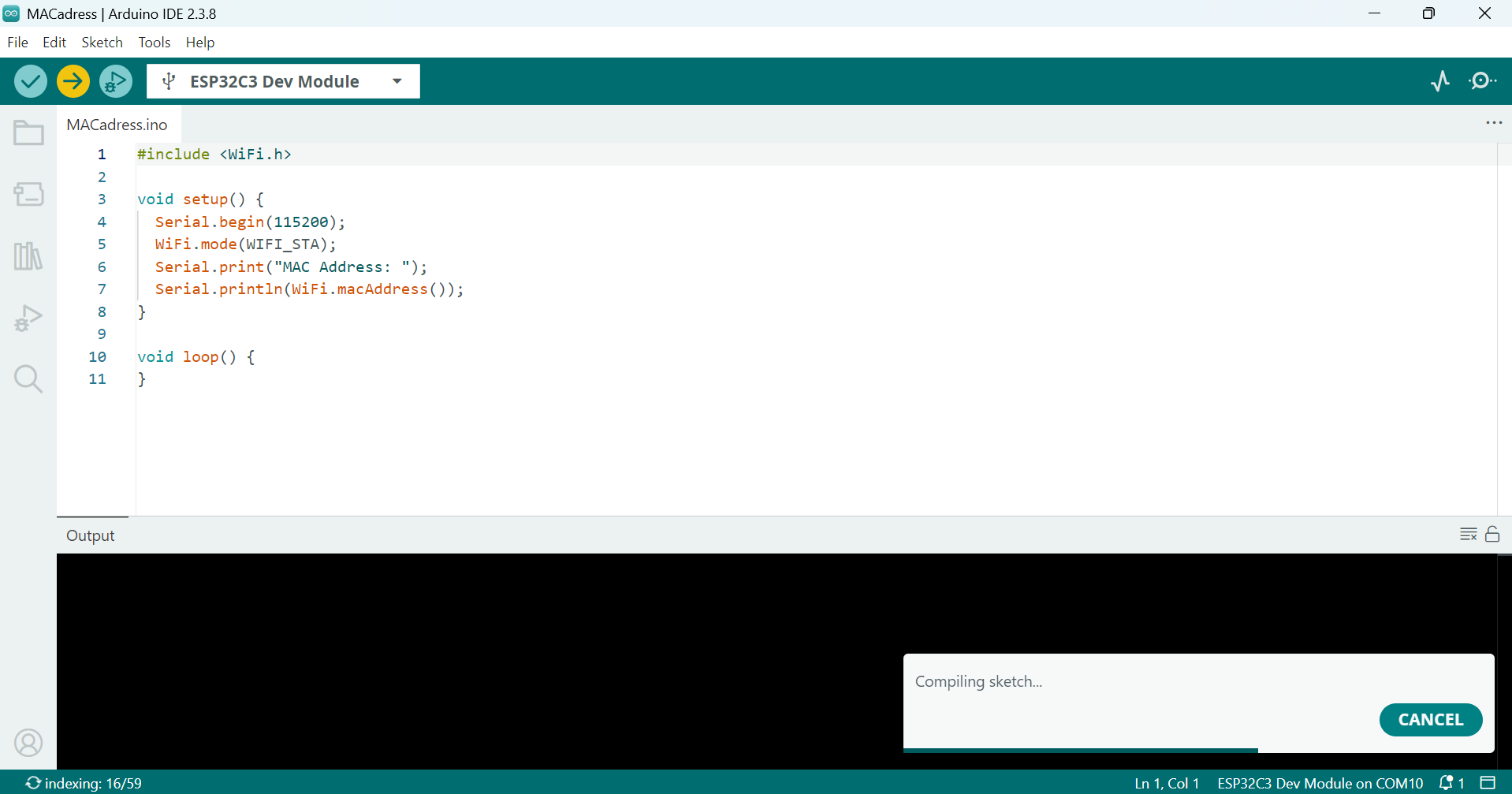
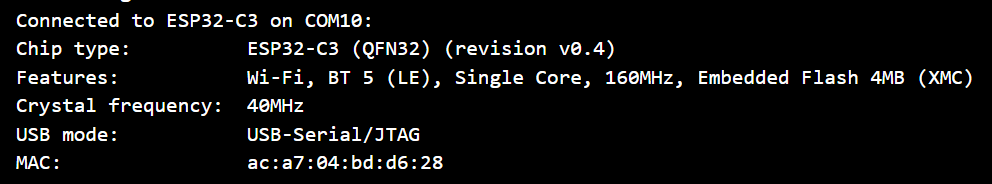
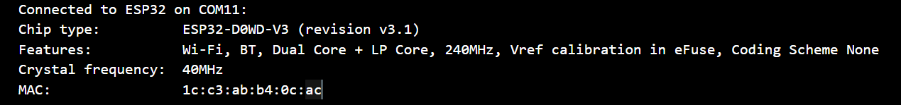
- Getting the MAC adress of each microcontroler.
- Testing a simple communication code to check everything works.
- Uploading the final version of the codes to each microcontroler:
- Checking the final version worked:
Code Breakdown
The following breakdown highlights the most relevant sections of the code used in this assignment. Each part is explained separately to show how the two ESP32 boards establish communication, exchange messages, and interact with local sensors and actuators.
1. Libraries and ESP-NOW Configuration
The first step is loading the required libraries. WiFi.h gives access to the ESP32 wireless hardware, esp_now.h enables ESP-NOW communication, and esp_wifi.h allows configuring the Wi-Fi channel manually.
#include <WiFi.h>
        #include <esp_now.h>
        #include <esp_wifi.h>
Both boards are configured as Wi-Fi stations. Although no router is involved, ESP-NOW uses the Wi-Fi hardware internally to exchange messages between devices.
WiFi.mode(WIFI_STA);
        WiFi.disconnect();
I also forced both boards to use the same Wi-Fi channel to make sure they could communicate with each other.
esp_wifi_set_promiscuous(true);
        esp_wifi_set_channel(1, WIFI_SECOND_CHAN_NONE);
        esp_wifi_set_promiscuous(false);
2. Peer Addressing
One of the requirements of this assignment was using network addresses. Each ESP32 board has a unique MAC address, and both devices must know the address of the other board before exchanging information.
In the DevKit code, I added the MAC address of the ESP32-C3-Zero:
uint8_t c3Address[] = {0xAC, 0xA7, 0x04, 0xBD, 0xD6, 0x28};In the ESP32-C3-Zero code, I added the MAC address of the ESP32 DevKit V1:
uint8_t devkitAddress[] = {0x1C, 0xC3, 0xAB, 0xB4, 0x0C, 0xAC};After defining the address, the board is registered as a peer. This creates a direct communication channel between both ESP32 boards.
esp_now_peer_info_t peerInfo = {};
        memcpy(peerInfo.peer_addr, c3Address, 6);
        peerInfo.channel = 1;
        peerInfo.encrypt = false;

        esp_now_add_peer(&peerInfo);
3. Shared Message Structure
Both microcontrollers use the same message structure. This is important because both boards need to interpret the messages in the same way.
typedef struct struct_message {
          char command[16];
          int value;
        } struct_message;
The command field contains short text instructions such as TRIGGER, ACK, or SOUND. The value field stores additional information, such as the microphone reading.
4. ESP32 DevKit V1 as the Main Controller
The ESP32 DevKit V1 works as the main controller. Its onboard BOOT button is configured as an input using INPUT_PULLUP.
const int buttonPin = 0;

        pinMode(buttonPin, INPUT_PULLUP);
When the BOOT button is pressed, the board creates a TRIGGER message and sends it to the ESP32-C3-Zero.
strcpy(outgoingMessage.command, "TRIGGER");
        outgoingMessage.value = 1;

        esp_now_send(c3Address, (uint8_t *)&outgoingMessage, sizeof(outgoingMessage));
The DevKit also listens for incoming messages. If it receives ACK, it confirms that the command was executed. If it receives SOUND, it prints the microphone value in the Serial Monitor.
if (strcmp(incomingMessage.command, "ACK") == 0) {
          Serial.println("ACK received from ESP32-C3");
        }

        if (strcmp(incomingMessage.command, "SOUND") == 0) {
          Serial.print("Sound detected from ESP32-C3 | mic value: ");
          Serial.println(incomingMessage.value);
        }
5. ESP32-C3-Zero as a Sensor and Actuator Node
The ESP32-C3-Zero works as a remote node. It manages three LEDs, a buzzer, a local button, and an analog microphone.
const int led1 = 6;
        const int led2 = 7;
        const int led3 = 8;

        const int buttonPin = 9;
        const int micPin = 1;
        const int buzzerPin = 5;
The board continuously listens for ESP-NOW messages. When it receives a TRIGGER command, it activates the remote LED and buzzer sequence.
if (strcmp(incomingMessage.command, "TRIGGER") == 0) {
          triggerReceived = true;
        }
6. Local and Remote Interaction Feedback
To make the interaction easier to understand, I created two different LED and buzzer sequences.
The local button on the ESP32-C3-Zero activates the original sequence: LED1, LED2, and LED3, with ascending tones.
void playLocalSequence() {
          digitalWrite(led1, HIGH);
          tone(buzzerPin, 523);
          delay(250);
          noTone(buzzerPin);
          delay(250);
          digitalWrite(led1, LOW);

          digitalWrite(led2, HIGH);
          tone(buzzerPin, 659);
          delay(250);
          noTone(buzzerPin);
          delay(250);
          digitalWrite(led2, LOW);

          digitalWrite(led3, HIGH);
          tone(buzzerPin, 784);
          delay(250);
          noTone(buzzerPin);
          delay(250);
          digitalWrite(led3, LOW);
        }
The remote trigger coming from the DevKit activates the sequence in reverse: LED3, LED2, and LED1, with descending tones.
void playRemoteSequence() {
          digitalWrite(led3, HIGH);
          tone(buzzerPin, 784);
          delay(250);
          noTone(buzzerPin);
          delay(250);
          digitalWrite(led3, LOW);

          digitalWrite(led2, HIGH);
          tone(buzzerPin, 659);
          delay(250);
          noTone(buzzerPin);
          delay(250);
          digitalWrite(led2, LOW);

          digitalWrite(led1, HIGH);
          tone(buzzerPin, 523);
          delay(250);
          noTone(buzzerPin);
          delay(250);
          digitalWrite(led1, LOW);
        }
7. Microphone Detection and Event Transmission
The microphone remains active while the ESP32-C3-Zero waits for commands. The analog value is read using analogRead().
int micValue = analogRead(micPin);If the microphone value goes above the threshold, the three LEDs turn on at the same time.
if (micValue > threshold) {
          allLedsOn();
        }
When sound is detected, the ESP32-C3-Zero sends a SOUND message back to the DevKit, including the microphone value.
strcpy(outgoingMessage.command, "SOUND");
        outgoingMessage.value = micValue;

        esp_now_send(devkitAddress, (uint8_t *)&outgoingMessage, sizeof(outgoingMessage));
To avoid flooding the network, the sound event is sent only when the signal first crosses the threshold, instead of being sent continuously.
if (!soundState) {
          soundState = true;
          sendSoundEvent(micValue);
        }
8. Avoiding Interference Between Actions
Since the LEDs are used by both the button sequences and the microphone feedback, I added a variable called isPlayingSequence.
bool isPlayingSequence = false;When a sequence is running, the microphone logic is temporarily paused. This prevents the microphone from turning all LEDs on while a button sequence is still playing.
if (!isPlayingSequence) {
          if (micValue > threshold) {
            allLedsOn();
          } else {
            allLedsOff();
            soundState = false;
          }
        }
9. Bidirectional Communication
One of the most important aspects of this assignment is that communication happens in both directions.
The DevKit sends commands to the ESP32-C3-Zero:
TRIGGERThe ESP32-C3-Zero responds with:
ACKIt can also generate independent sensor events:
SOUNDThis creates a simple distributed system where one node can control another while also receiving information from remote sensors.
Download all files