Week 5: 3D Scanning and Printing
Additive Manufacturing
3D printing or additive manufacturing is a process of making three-dimensional objects from a digital file.
The creation of a 3D printed object is achieved using additive processes. In an additive process an object is created by laying down successive layers of material until the object is created. Each of these layers can be seen as a thinly sliced cross-section of the object and they're are made through G-CODE.
G-CODE is a programming language for CNC that instructs machines where and how to move. The G in G-CODE stands for "Geometric" because is the type of movement the code produces.
G-CODEN## G## X## Y## Z## F## S## T## M## N##: Line Number.G##: Motion.X##: Horizontal Position (X axis).Y##: Vertical Position (Y axis).Z##: Depth (Z axis).F##: Feed Rate.S##: Spindle Speed.T##: Tool selection.M##: Miscellaneous functions.Miscellaneous functionsM00:Program stop. M01:Optional program stop. M02:End or program. M03:Spindle on clockwise. M04:Spindle on counterclockwise. M05:Spindle stop. M06:Tool change. M07:Flood coolant on. M08:Flood coolant off. M30:End of program / Return to start. M41:Spindle low gear range. M42:Spindle high gear range.
For more information i recomend to take a look at this webpage Good source.
Types of additive manufacturing
According to the International Organization for Standarization (ISO) there are 7 types of additive manufacturing.
1. VAT Photopolymerisation
It is also known as stereolithography. This type of additive manufacturing uses a vat of liquid photopolymer resin. The process consists in a build platform located on the top, that moves downward, and a laser beam draws a shape in the resin, creating a layer, then the platform moves upward to make space for the new layer and the process repeats until the model is complete.
This process of photopolymerization uses motor controlled mirrors to direct the UV across the resin surface, until it hardens, and then reapiting this process until the piece is done.
The average thickness of one layer is between 0.025 and 0.5mm and after the piece is done, it has to be cured using UV light.
This process delivers pretty accurate pieces.
2. Material Jetting
Similiar to inkjet priniting. The print head is above the platform and the material is deposited onto the surfoce in form of droplets.
This droplets are positioned with control and accuracy, then they're solidified using UV lights, making the layers. The droplets are oftenly made of polymers and waxes.
Although accurate, it is not the most efficient method as time is spent re-filling the reservoir that depletes quickly. Is often used to create realistic models or prototypes.
3. Binder Jetting
Is one of the speediest additive manufacturing methods and allows for customization.
Uses a binder and a powder-based material which is applied to the build platform with a roller and then the print head deposits the binder on top.
The binder adheres the layers together and is usually in liquid form. Following a layer, the product is lowered on the platform. This is repeated to create more layers until the product is finished.
4. Material Extrusion
Consists on the material being drawn through a nozzle heated and then deposited in a continuous stream on the build plate.
The layers are formed because of the material fusing itself with te previous faces.
It is one of the cheapest ways of manufacturing, but the accuracy is reduced because of the nozzle thickness and the material extrusion is also one of the slower types of additive manufacturing.
Fused Deposition Modeling (FDM): Material is drawn through a nozzle, where it is heated and is then deposited layer by layer.
5. Powder Bed Fusion
Consists on a layer of powder being applied to the platform and a thermal source like an electron beam or laser fuses it before another layer is placed. This process is repeated until the piece is done.
There are slight variations within powder bed fusion, including:
Selective Laser Sintering (SLS): Uses a high-powered laser to fuse small particles of polymer powder into solid structures.
Electron Beam Melting (EBM): Uses a high-power electron beam to melt conductive metal powder in a vacuum, making a sloid structure.
Selective Laser Melting (SLM): Uses a high-power laser to fully melt metal powders layer by layer to create a complex 3D part.
Direct Metal Laser Sintering (DMLS): Uses a high-powered laser to fuse fine metal powder layer by layer to make a solid structure.
There are some disadvantages to the powder bed fusion method as it requires more time to complete projects; however, this additive manufacturing process is still used in various industries, including aviation, to create parts of a jet engine.
6. Sheet Lamination
Sheet lamination is a process that binds layers using ultrasonic welding or an adhesive.
There are two methods for sheet lamination, Unltrasonic Additive Manufacturing (UAM) and Laminated Object Manufacturing (LOM).
UAM: Uses metal that is bound together with ultrasonic welding.
LOM: Uses paper that is bound together using an adhesive.
This process sometimes lacks of accuracy. But it can be used for prototypes.
7. Directed Energy Deposition
Is one of the most complex types of additive manufacturing. A four- or five-axis arm will move around, depositing melted material around a fixed object. The material is melted by an electron beam or laser and will then solidify.
Metal powder or wires are the most common material used with DED, but ceramics and polymers may also be used. You can achieve a high degree of accuracy due to the ability to repair and control grain structure in DED.FDM Materials
| Material | Description | Printing Temperature | Advantages | Disadvantages | Hardware Requirements |
|---|---|---|---|---|---|
| PLA | A biodegradable thermoplastic derived from renewable resources like corn starch. It's the standard for desktop printing due to its minimal thermal expansion. | Extruder: 190-220 °C Bed: 50-80 °C |
Easy to print, low cost, rigid, and great surface detail. | Brittle, low heat resistance (deforms above 60°C). | Standard FDM printer. |
| ABS | A petroleum-based thermoplastic known for its impact resistance and toughness. It allows for post-processing with acetone for a smooth finish. | Nozzle: 230-250 °C Bed: 80-110 °C |
Impact & wear resistant, durable, and affordable. | Prone to warping (shrinkage), emits unpleasant fumes. | Heated bed and enclosed chamber recommended. |
| PETG | The "middle ground" material. It combines the ease of use of PLA with the functional strength and chemical resistance of ABS. | Nozzle: 230-250 °C Bed: 70-80 °C |
Excellent mechanical properties, water-resistant, and recyclable. | High "stringing" (hairs), can stick too well to the bed. | Standard FDM printer. |
| Nylon | A high-performance semi-flexible polymer. Offers the best combination of strength, compliance, and fatigue resistance for mechanical parts. | Nozzle: 240-260 °C Bed: 70-100 °C |
Extremely tough, low friction, and high chemical resistance. | Highly hygroscopic (absorbs moisture), difficult bed adhesion. | All-metal hotend and dry storage required. |
| TPU / Flexible | A Thermoplastic Elastomer (TPE) that behaves like rubber. It can be stretched and compressed without losing its original shape. | Nozzle: 210-230 °C Bed: 20-60 °C |
High shock absorption, flexible, and very durable. | Hard to print with Bowden tubes, needs slow speeds. | Direct drive extruder preferred. |
| ASA | Alternative to ABS with improved weather resistance. Specifically designed to withstand UV radiation without degrading. | Nozzle: 240-260 °C Bed: 90-110 °C |
UV resistant, high impact and wear resistance. | Expensive, emits styrene fumes during printing. | Heated enclosure and ventilated area. |
| Composite (CF, Wood, Metal) | Base polymers (PLA/PETG) infused with fibers or powders to change their aesthetic or physical properties. | Variable (follows base material) | Unique finishes (wood/metal) or increased stiffness (Carbon Fiber). | Highly abrasive, can clog standard nozzles easily. | Hardened steel nozzle required. |
Filament 3D Printing
Steps
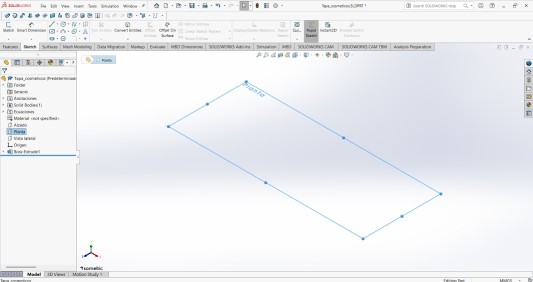
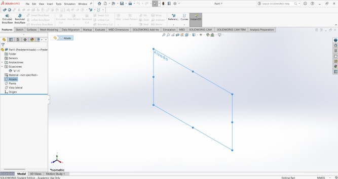
1.First I created a sketch in the Top plane.
Steps
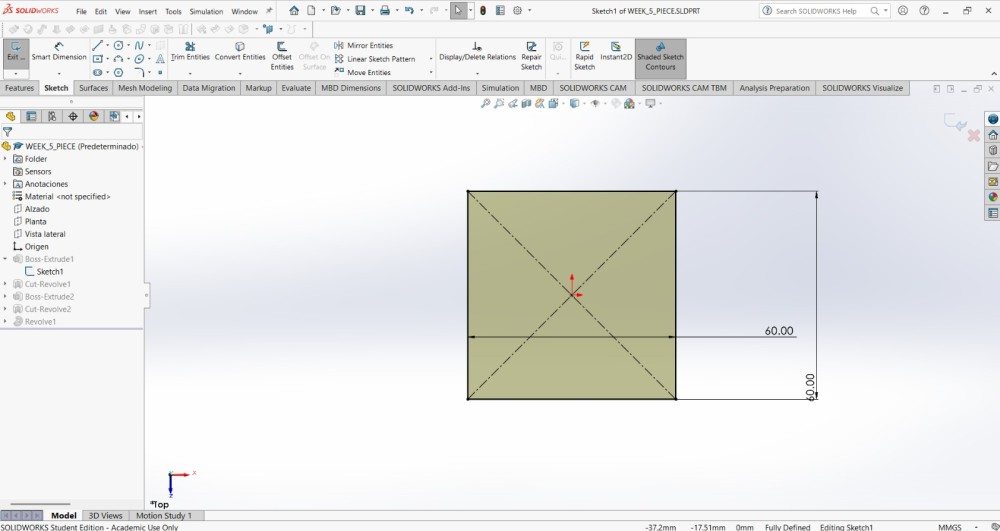
2.Then I made a 60X60 mm using the Center Rectangle tool.
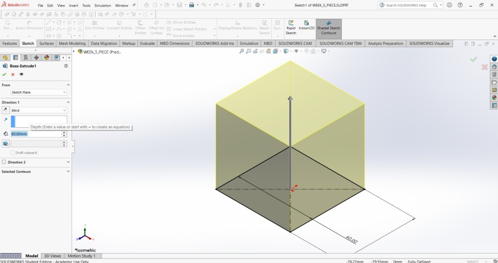
3.After that, I extruded it 60 mm.
Steps
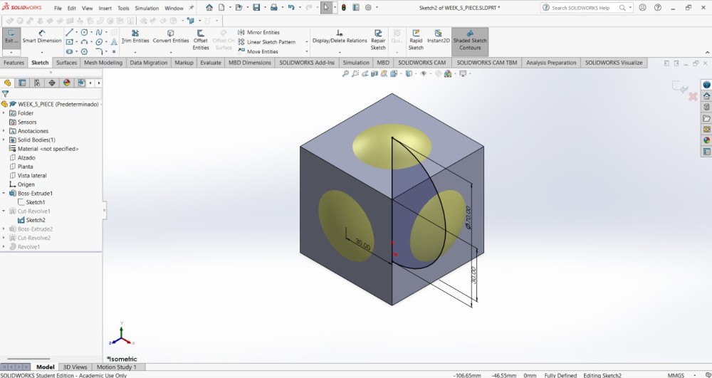
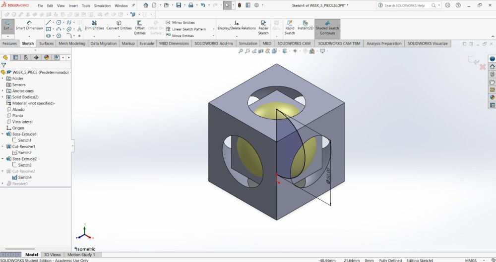
4.Subsequently, in the front plane, I made at the center of the cube half a circle of 70 mm of diameter and revolved it using the revolve cut tool.
Steps
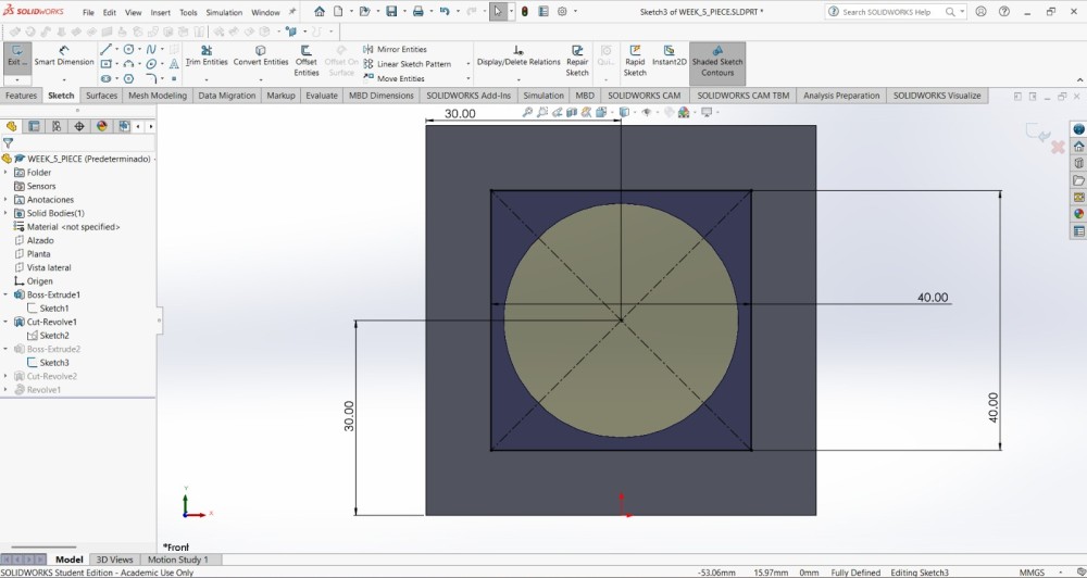
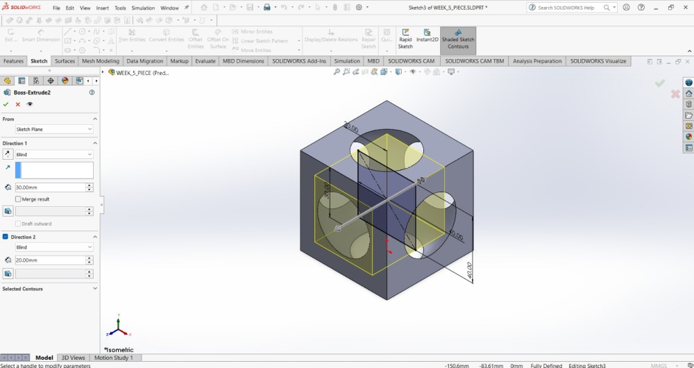
5. Here comes the funny part, I made another cube inside the cube, of 40x40 mm, but this time i extruded 20 mm in one direction and 20 mm in the opposite.
Steps
7. Inside that cube I made another half circle in the center, as the other one, it was in the front plane and it also was 10 mm longer than the cube lenght. The idea behind that is to exceed a little bit the cube in every face in order tu create a circular shape in every face.
I revolved the half circle of 50 mm diameter with the revolve cut tool.
Steps
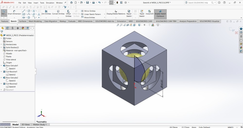
8. Finally, I made another half circle inside the cube inside the other cube. This half circle was of 40 mm diameter in order to not be able to get out the cube, because the circular shape y tinier than the sphere. I revolved the shape using the revolve tool.
9.To export our piece, we have to File in the top menu and save our piece as an STL document.
ULTIMAKER CURA
Is a free, open-source 3D printing slicing application that prepares 3D models (STL, 3MF, OBJ) for printing by translating them into machine-readable G-code. It can be installed in the official website.

Add a printer
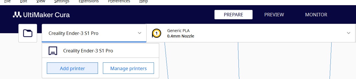
1.To add a printer we have to click on the tab and select add a printer.
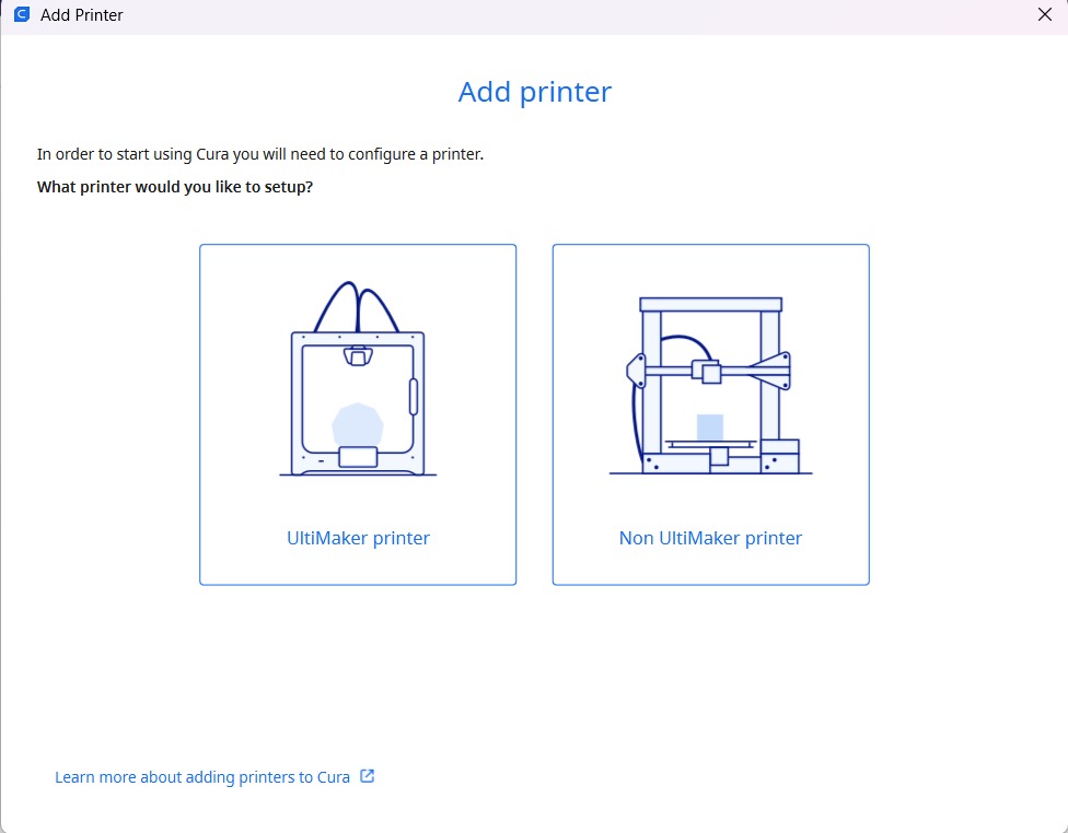
2.Then the program will ask if we want to add an ultimaker printer or a Non ultimaker printer.
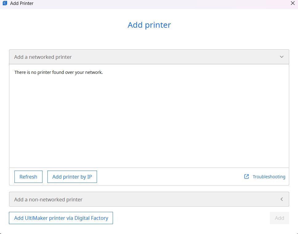
3.And then add a local printer and follow the steps.
Steps
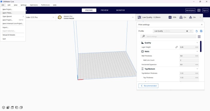
1.After creating a new project (which is created opennig the program), we must go to the top menu, in File and open an STL file.
Steps
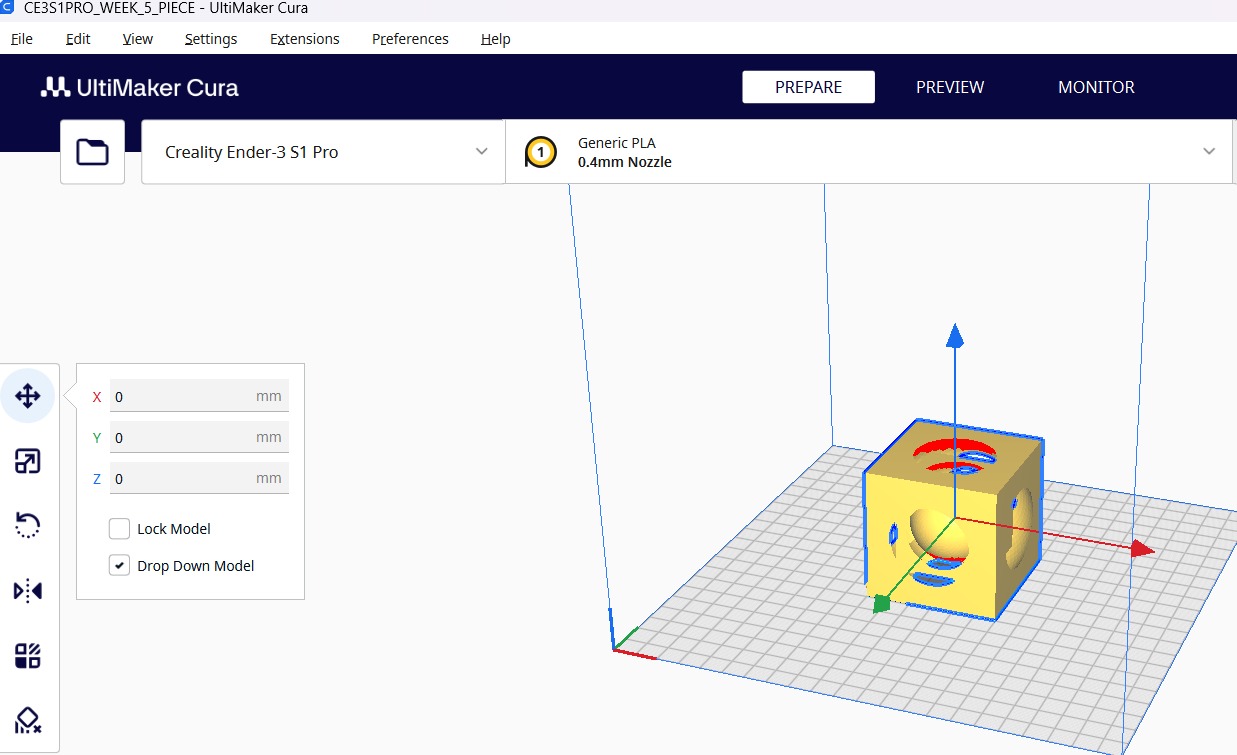
2.After opening our file we have to set the printer values. It is important to notice if our piece is in the right position, if we want to change its position after slicing it, we'll have to do it again.
Piece tools (First picture)
Move: To move our piece.
Scale: To scale our piece.
Rotate: To rotate our piece.
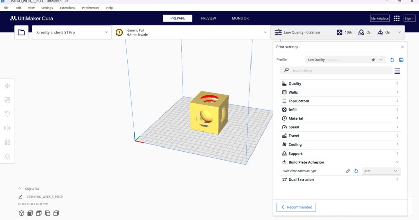
Printer tools (Second picture)
Quality: Sets the quality and the layer height of our piece.Walls: Sets the wall thickness, wall line count and the horizontal expansion of a wall.Top/Bottom: Sets the top and bottom thickness and number of layers.Infill: Sets the infill density and the pattern of the piece.Material: Sets the temperature of the extruder and the plate.Speed: Sets the print speed in mm/s.Travel: Enables retraction.Cooling: Sets the fan speed.Support: Add suports and sets its placement, structure and overhang angle.Build Plate Adhesion: Sets the build plate adhesion type.Steps
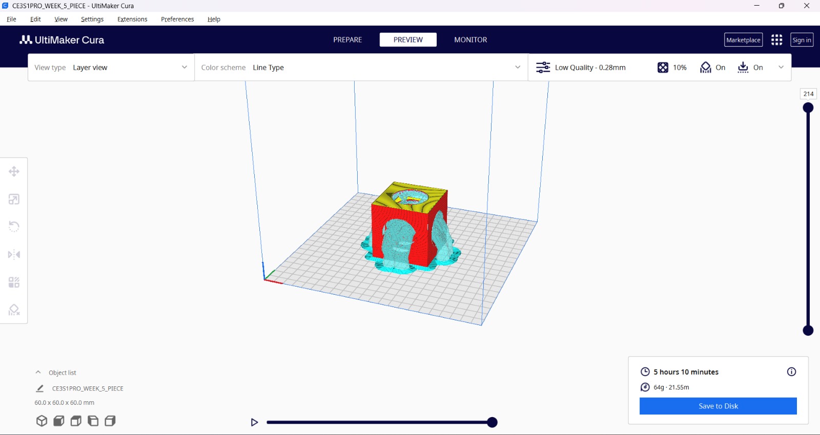
3. Then we have to set the parameters and slice it.
My parameters
| Setting Group | Parameter | Value | Description |
|---|---|---|---|
| Quality | Layer Height | 0.28 mm | Determines the thickness of each layer. |
| Initial Layer Height | 0.2 mm | The height of the very first layer; usually thinner to improve bed adhesion. | |
| Shell | Wall Thickness | 2 mm | The total width of the outer vertical walls of the object. |
| Top Layers | 4 | The number of solid horizontal layers on the top surface for a smooth finish. | |
| Infillt | 10 % | Cubic. | |
| Speed | Print Speed | 100.0 mm/s | The speed at which the extruder moves while printing.. |
| Bed Temperature | Build Plate Temp | 80.0 °C | The temperature of the bed, because i used PLA. |
| Extruder temperature | Build Plate Temp | 210.0 °C | In order to really melt the PLA. |
| Adhesion & Support | Build Plate Adhesion | Brim / Skirt | Helper structures to ensure the print sticks to the bed and the nozzle is primed. |
| Support | Three | Because it brings more strenght to the support. | |
| Cooling | Fan Speed. | 100 mm/s. | It has to be well cooled. |
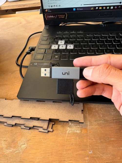
4. Finally, we have to save it to a disk, for that we can use an USB adapter. What we will save is a G-CODE.
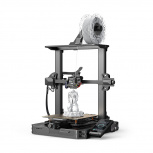
3D Printer
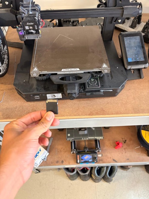
For printing my piece I used a Creality Ender-3 S1 Pro.
Steps
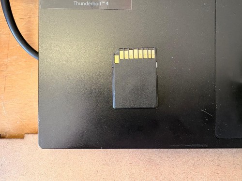
1. First I took the SD card attached to the printer.
2. Then I used a USB adapter and uploaded my G-CODE.
Steps
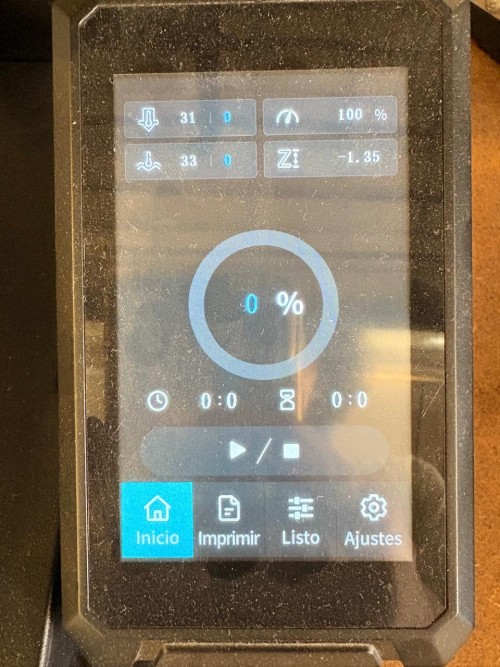
3.Subsequently, I attached the SD card again and look for the files in the "imprimir" (print) section.
Steps
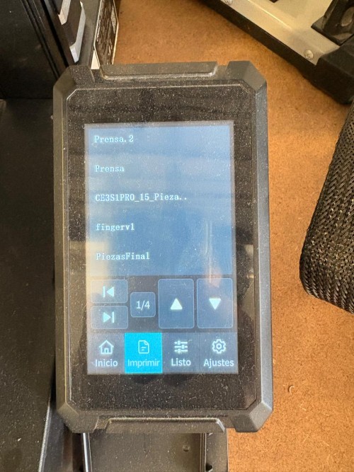
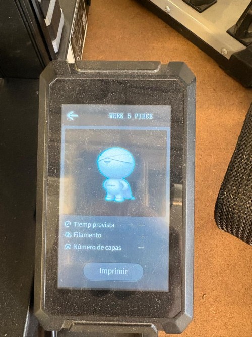
5. Finally, I selected my file and started to print.
Resin 3D Printing
3D scanning
For scanning I used CrealityScan. CrealityScan is a 3D scanning software designed for scanners under Creality 3D, with rich features to help users achieve high-quality scanning and complete model building. To download it, we must go to this website and download the most recent version.

Steps
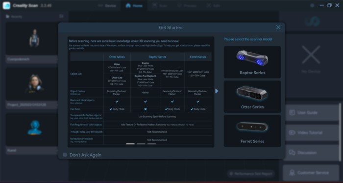
1. After downoading the software, it will ask for a connection to a Creality family scanner.
Steps
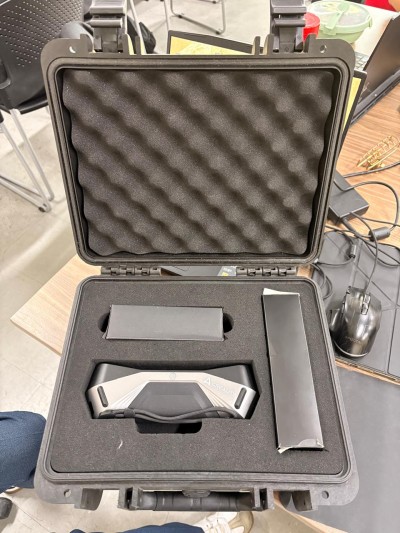
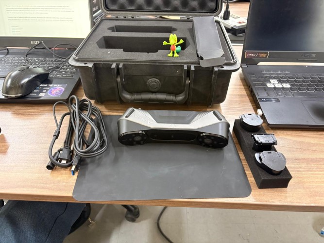
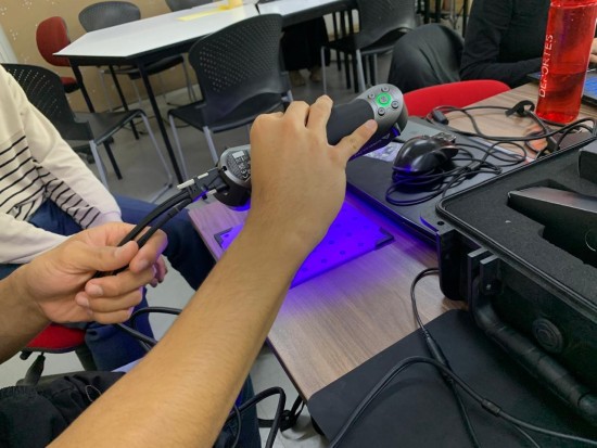
CR-Scan Raptor. Is a portable device that combines blue laser and infrared light sources to scan objects.
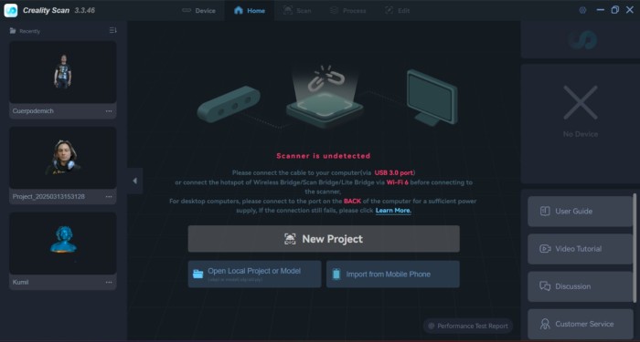
2. For using the scanner, first we have to connect it to the computer and the software will automatically recognize it.
Steps
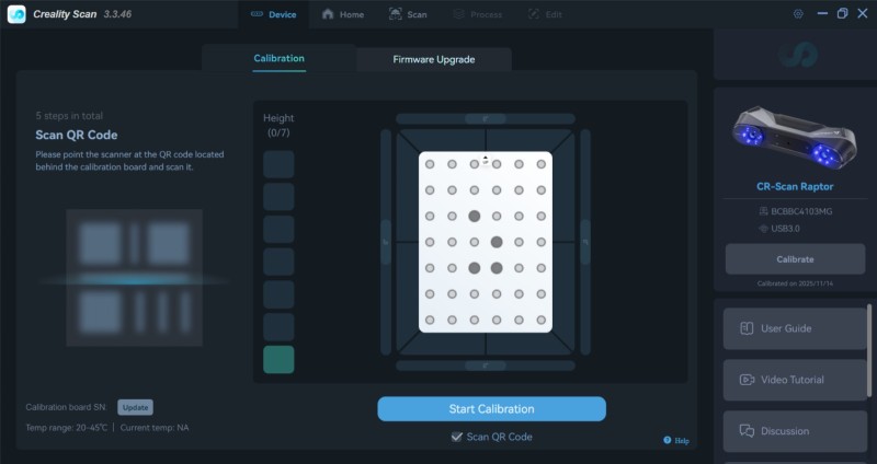
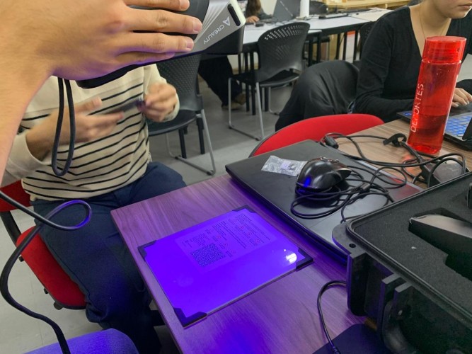
3. Scan a QR code that comes in the box to calibrate the board.
Steps
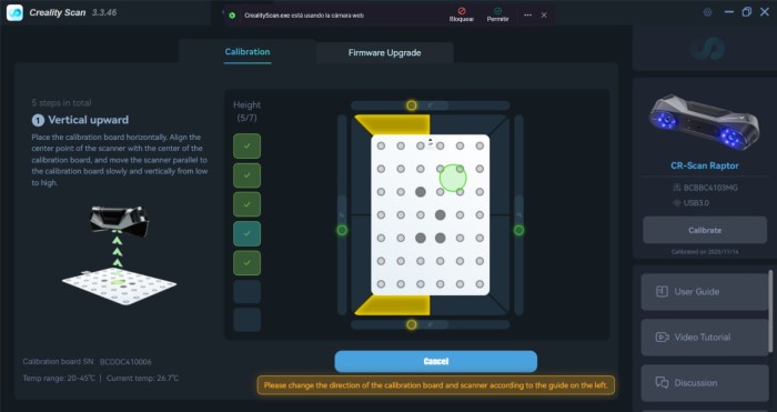
4. Then we have to scan in different positions the calibration board to calibrate our Scanner.
Steps
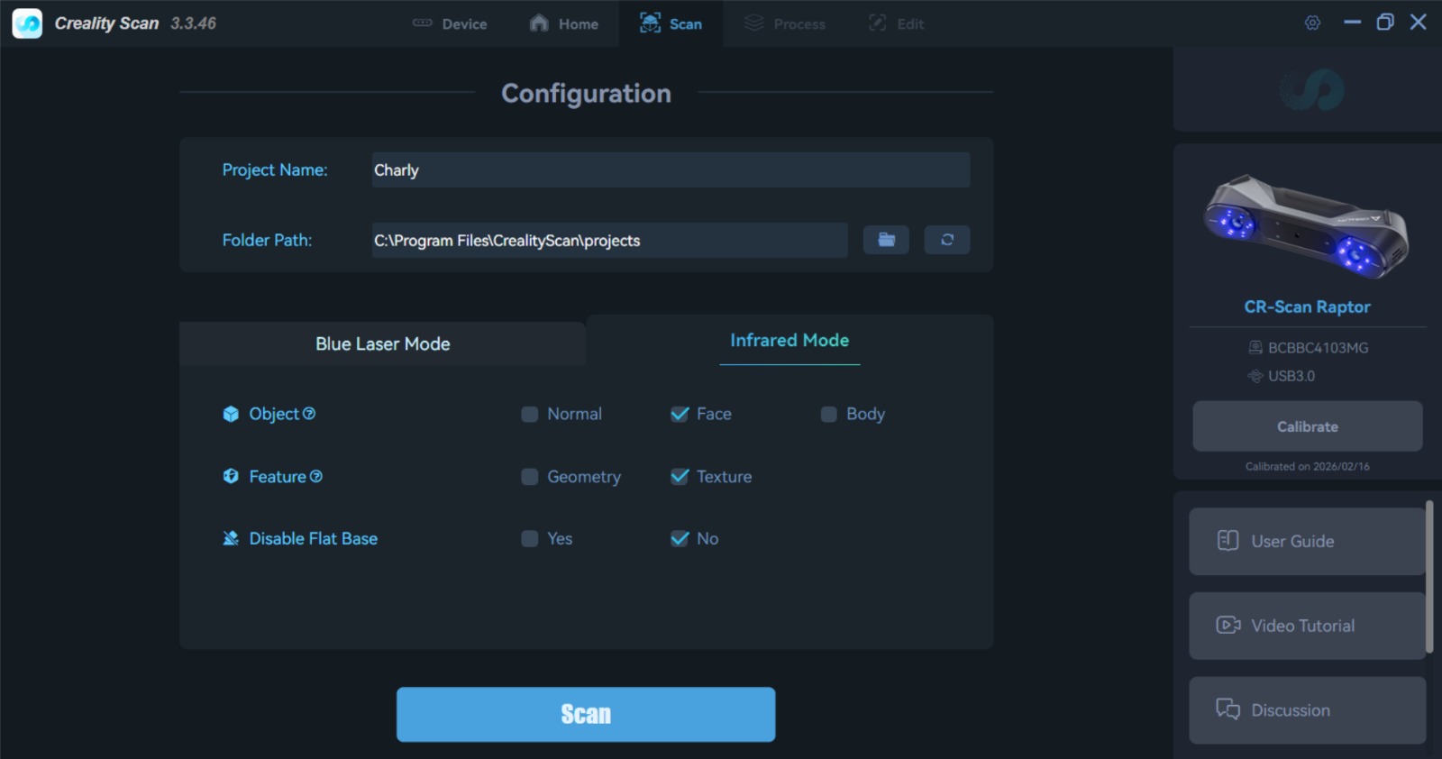
5. Once we have calibrated our scanner, we will return to the menu and start a new project. For our scanner, the settings should be infrared, face, texture, and disable the flat base.
Steps
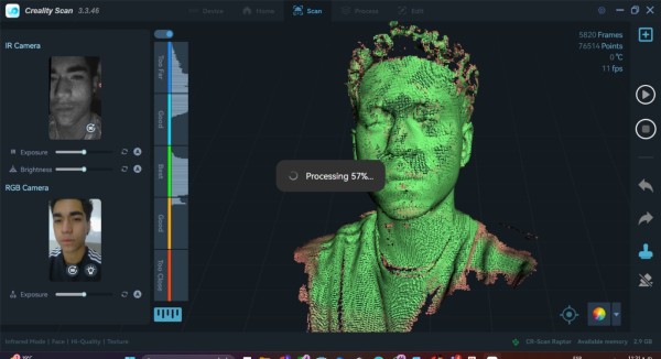
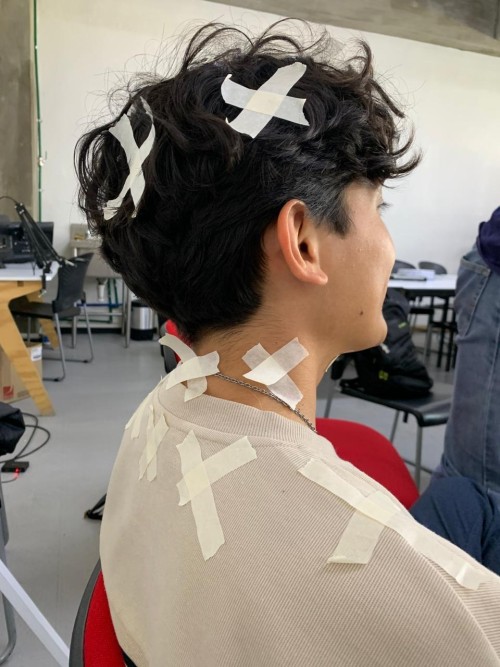
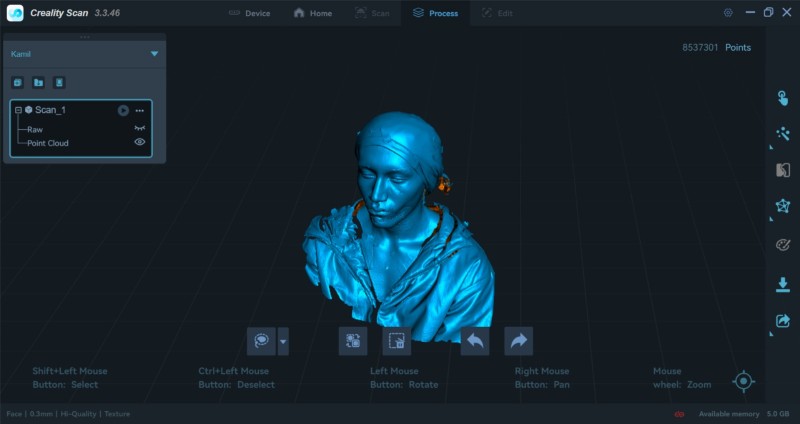
6. Next, we will need to slowly move the scanner around our surface. The scanner gets lost on very dark surfaces, so it is important to add references to guide the laser.
Steps
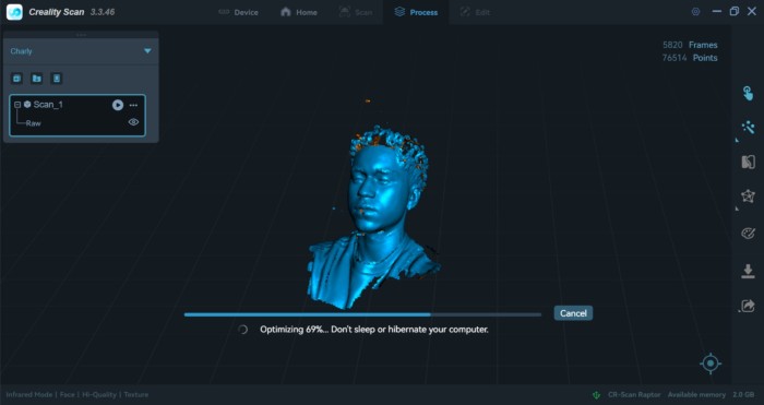


7. Finally, we need to mesh our scan and export it, either as STL or obj.
To mesh the scan we have to click in the One-click process button.
To export the piece we have to click in the Export button.
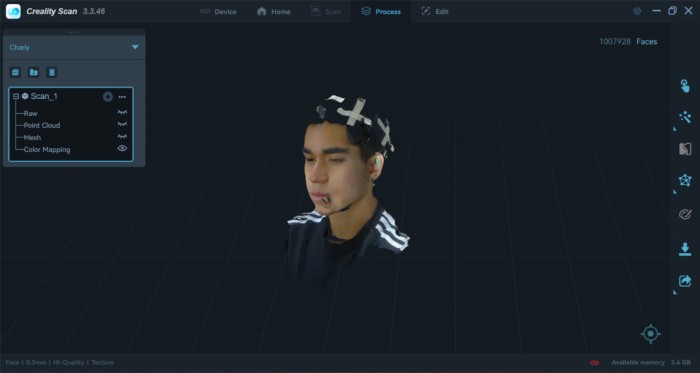
My Scan
Scanning Process
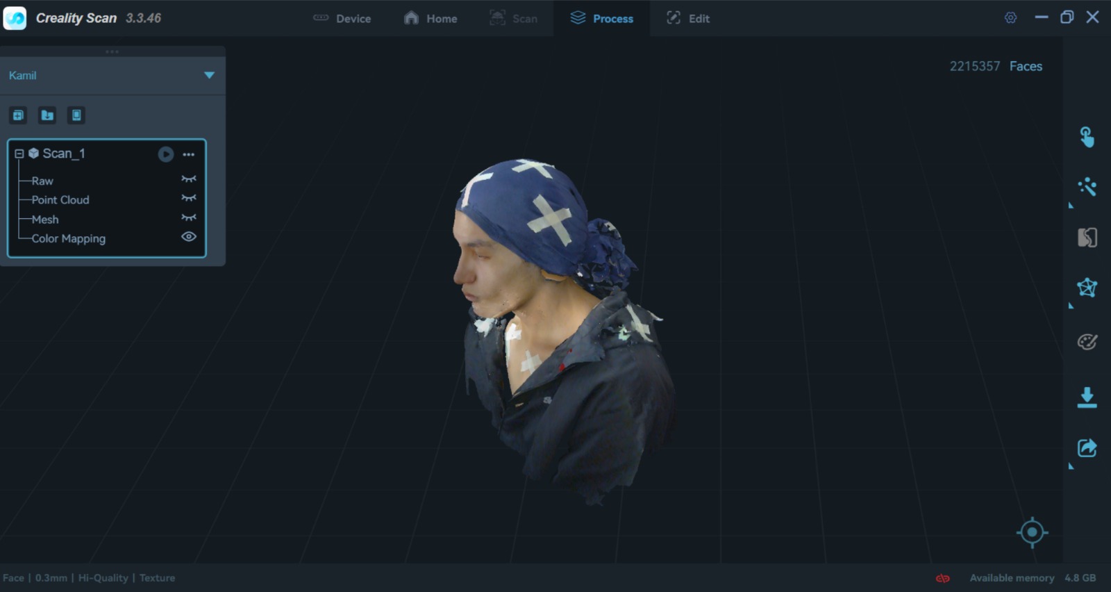
EXTRA. I followed the same steps but with my head, because my hair is very long and black, the scanner kept losing track, so I decided to put my shirt over my head. We also placed reference points in different places where the scanner kept losing track.
Meshmixer
Is a free software developed by Autodesk intended for easy creation of 3D mashups. Lets you sculpt, repair, slice, hollow, and blend STL/OBJ files. Here you can download meshmixer.
Steps for making a solid our STL
1. We have to open Meshmixer and import our STL.
Steps for making a solid our STL
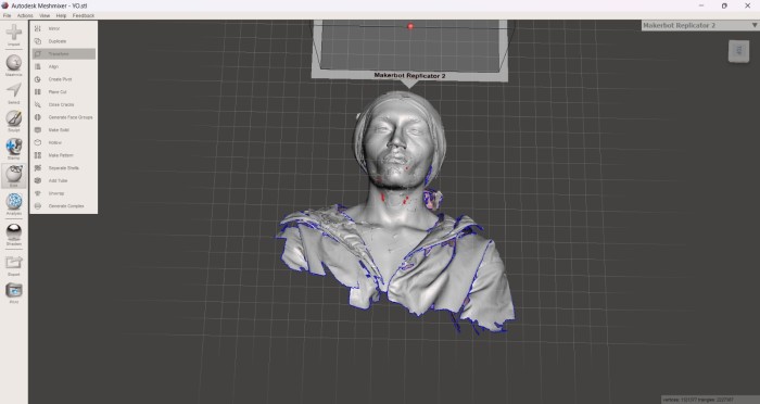
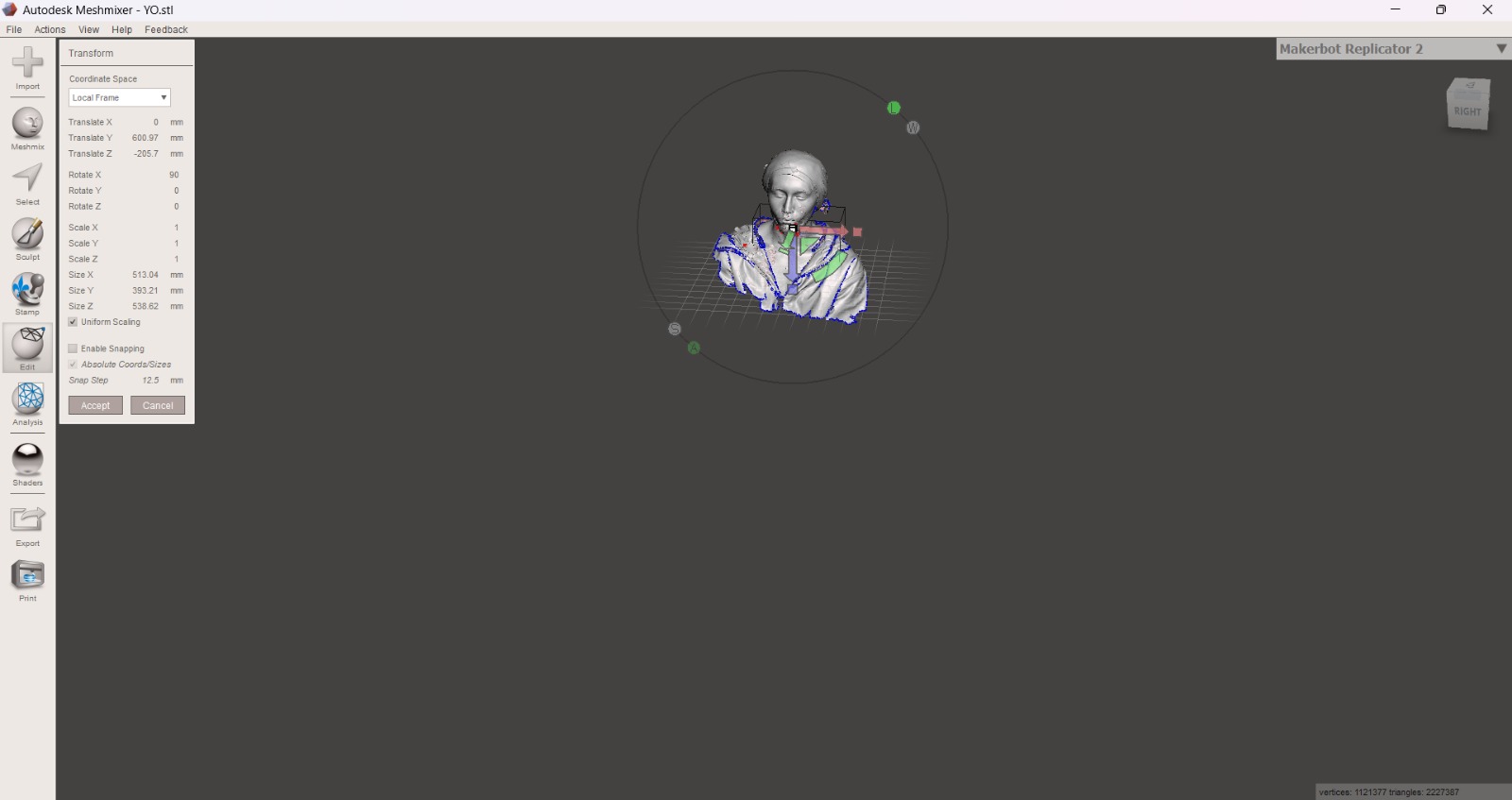
2. After importing our STL, we have to move and rotate it. For that we must use the Edit tool in the left menu and select the Transform option.
In Transform we can move the position of our STL, rotate it and scale its size.
Steps for making a solid our STL
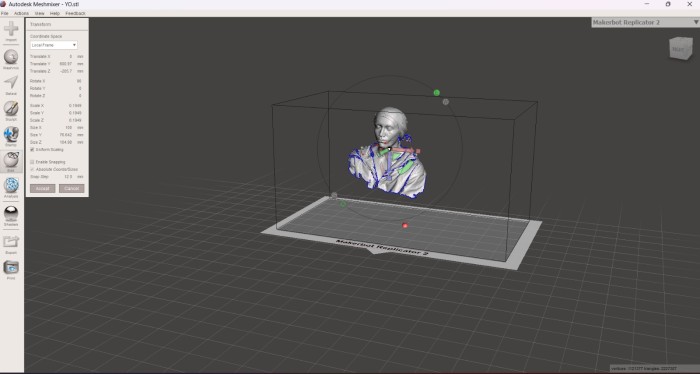
3. After changing the position of the STL, I scaled it to 100 mm in the X axis.
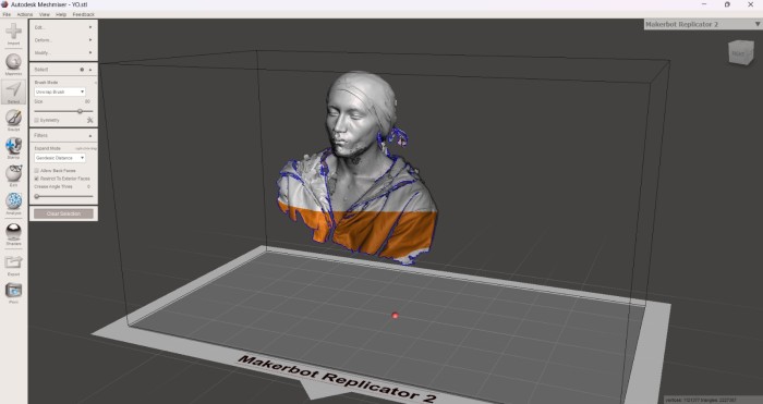
4. And using the Select tool in the left menu, we can cut the parts of the mesh that we don't want to work with. In this case I just want my head.
Steps for making a solid our STL
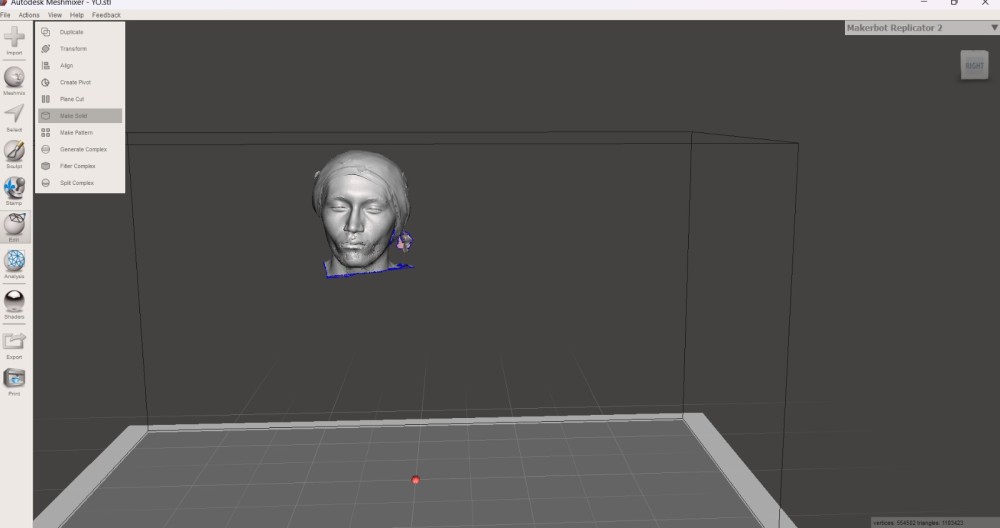
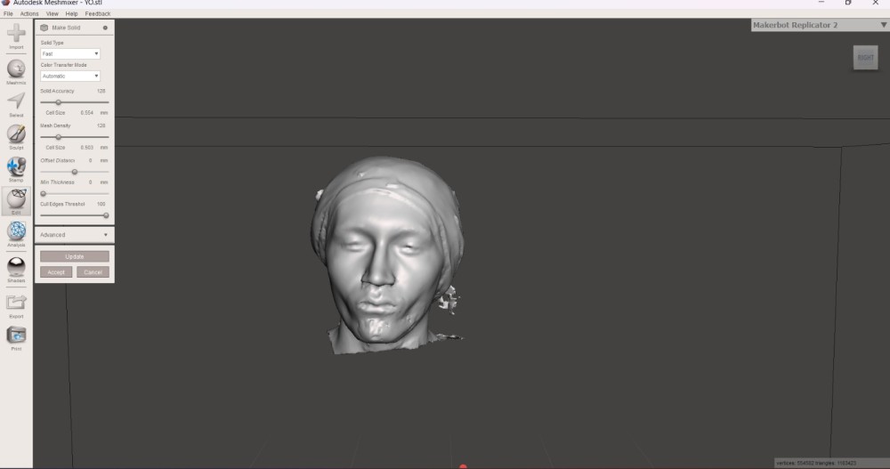
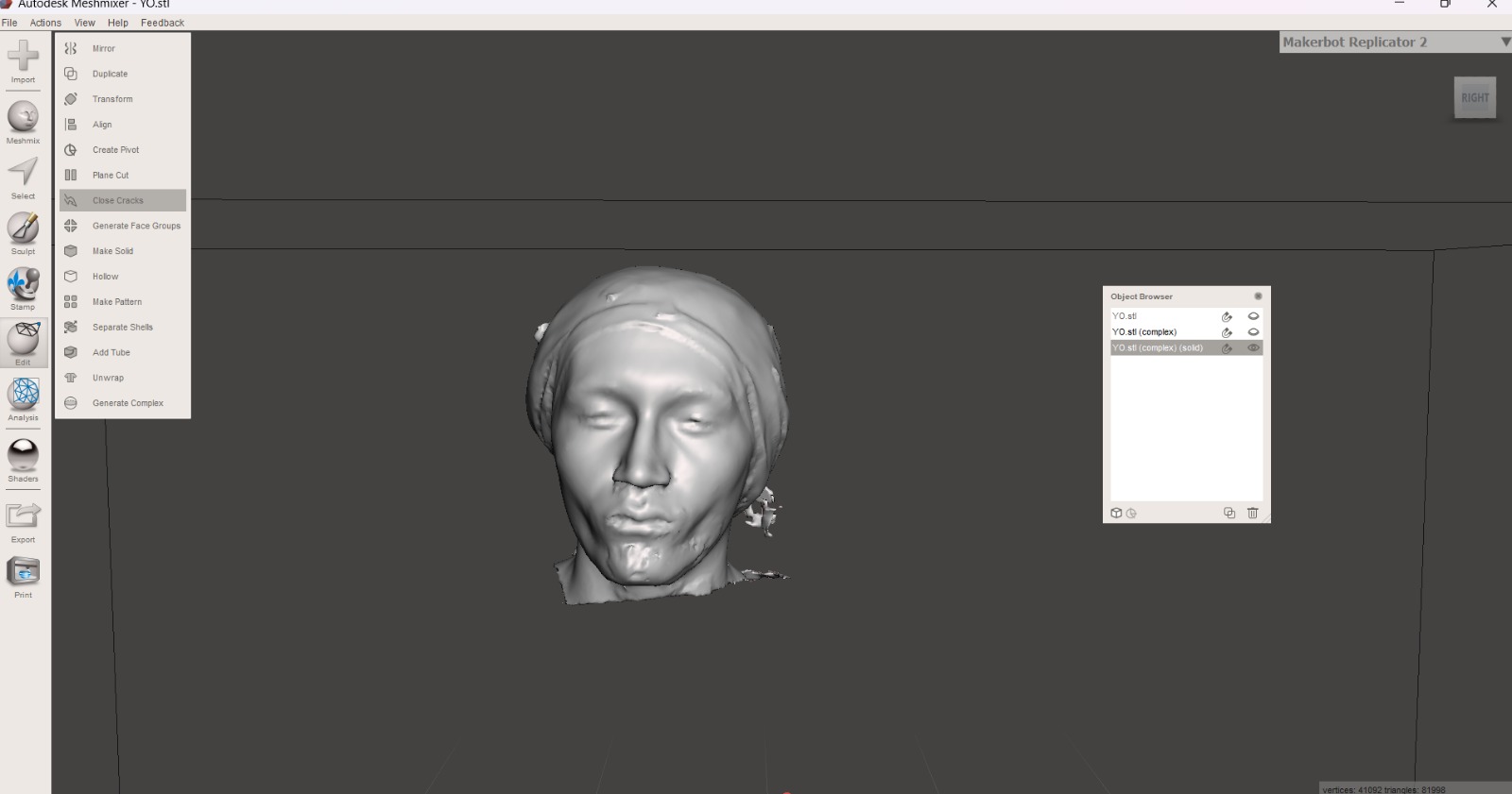
5. Then, with the Edit tool and selecting Make a solid we can do exactly that, and select the quality and quantity of nodes we want our solid to have.
6. In Edit we can also select Close cracks to also do what the tool says.
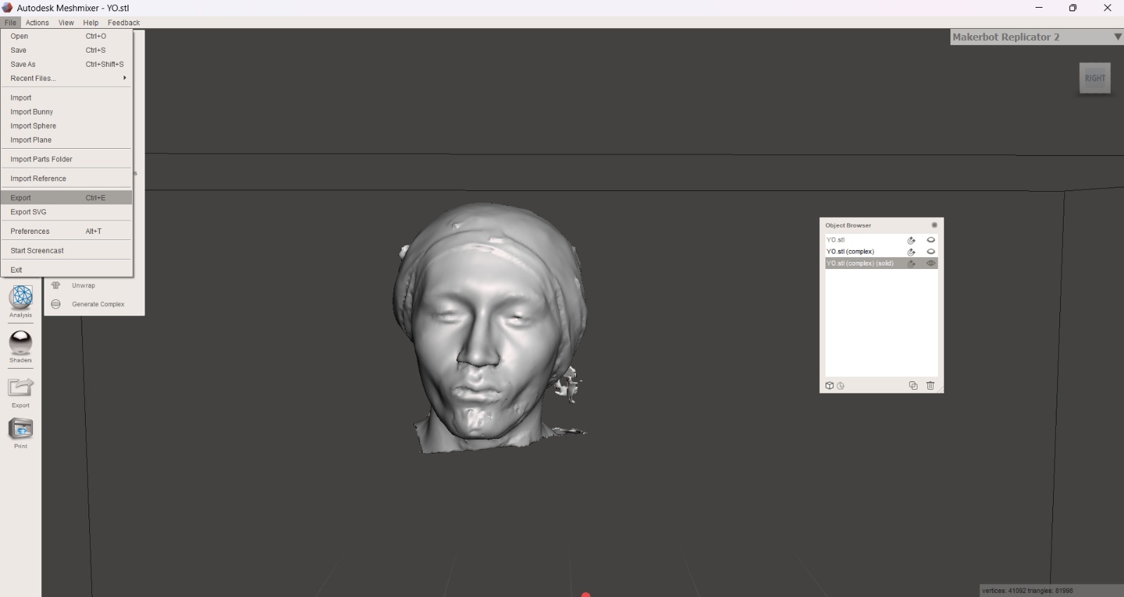
7. Finally, we can export our file by clicking on FILE and then EXPORT. We must export it as an STL for the next steps.
AnyCubic Photon Workshop
Anycubic Photon Workshop is a free, proprietary 3D slicing software developed by Anycubic specifically for their resin printers. It converts 3D models (STL/OBJ files) into sliced files (.pws, .photon) with custom support generation, model hollowing, and exposure settings. Here you can download AnyCubic Photon Workshop.
Steps
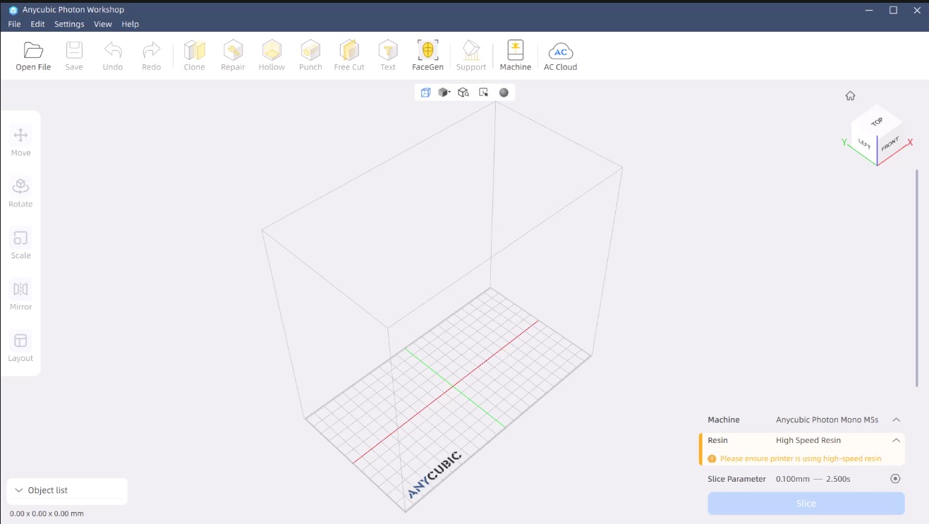
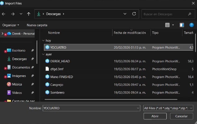
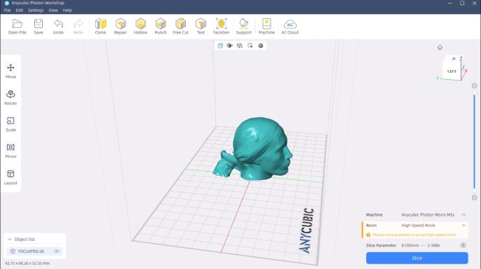
1. We have to open Anycubic Photon Workshop and import our STL.
Steps
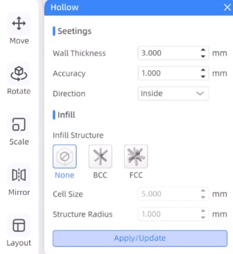
2.Next, we will hollow out the figure and assign an appropriate thickness to its walls. In my case, I selected a thickness of 3 mm. The Hollos function is useful for saving resin and preventing it from detaching from the bed, which in this case is upside down.
Steps
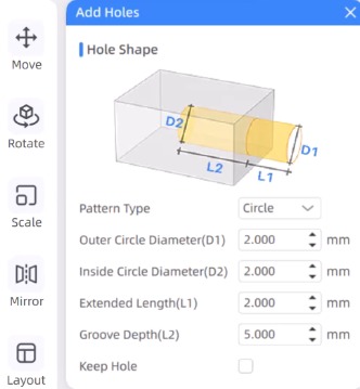
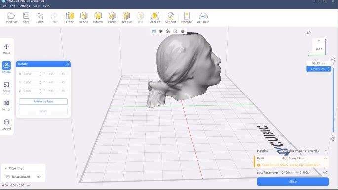
3. We will then add two holes in order to release the air inside the figure and the residual resin.
4. Next, we will tilt the figure 45 degrees, since minimizing the surface area of each layer drastically reduces the suction force that separates the piece from the tank, improving print quality, releasing residual resin, and making it difficult for it to detach from the plate.
Steps
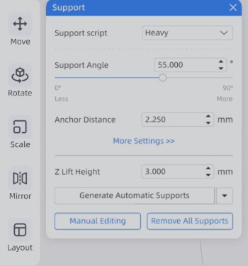
5. Then, we have to add supports in order to facilitate the printing process. The software offers three types of supports: Light, Medium and Heavy. I choose heave because it brings more grip.
Support parameters
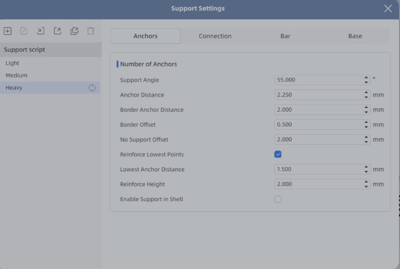
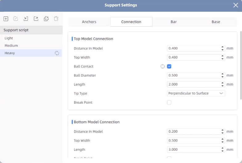
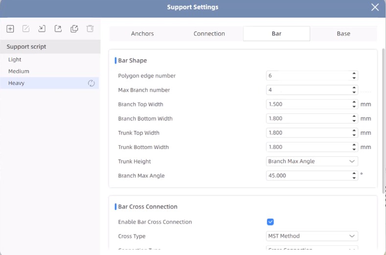
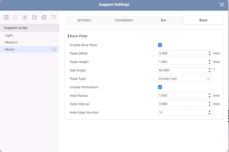
Parameters.Shortly, this parameters allows us to set the anchors characteristics, in my opinion the most relevant one is the support angle. We can also set Model connection, Bar shape, Base Plate. The ones that we must pay more attention in order to obtain a better printing are the plate type, plate offset, Trunk Height and Branch Max angle.
Steps
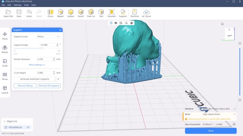
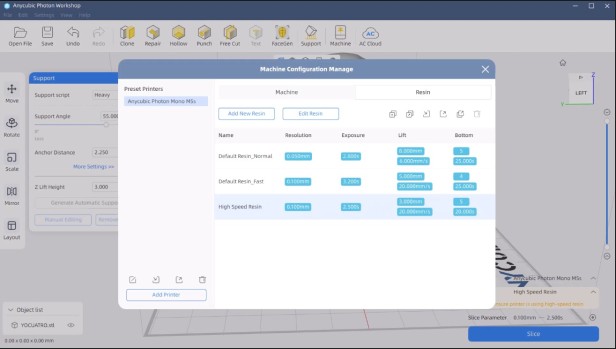
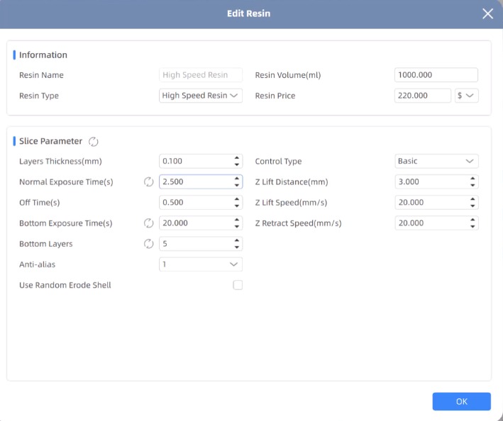
6. To slice we have to click the button in the bottom right. But before slicing we have to make sure of having the correct resin. In my lab we have High Speed Resin, so that is the one I used.
Resins. There are 3 types of resin:
High Speed Resin
Standard Normal
Standard Fast
7. Finally, we have to save it in a USB disk.
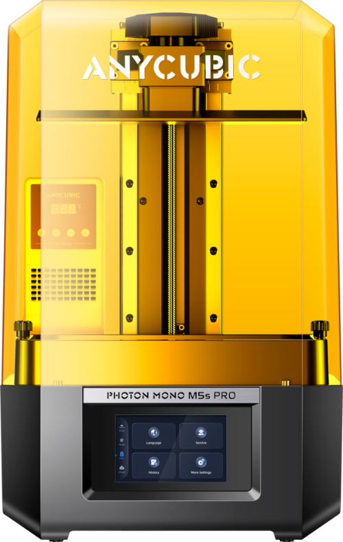
3D Printer
For printing my piece I used an ANYCUBIC PHOTON M5s.
Steps
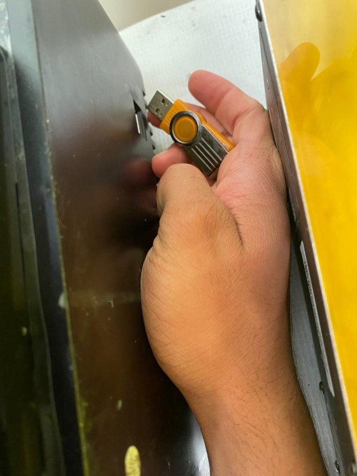
1. First, I connected my USB adapter so I could load my document.
Steps
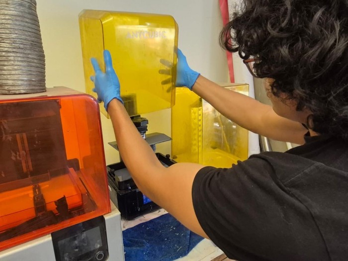
2. Then I removed the cover.
Steps
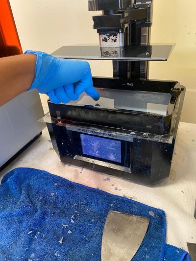
3. After that, I made sure that there was nothing that may obstruct the printing process.
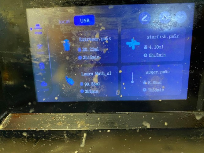
4. Then I logged into the USB and uploaded my document.
Steps
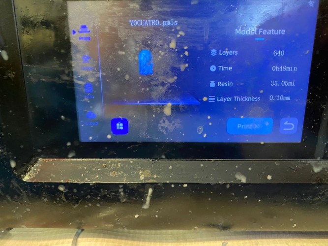
5. After that, I started the printing.
Steps
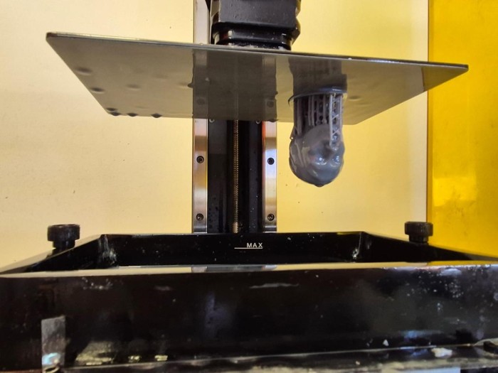
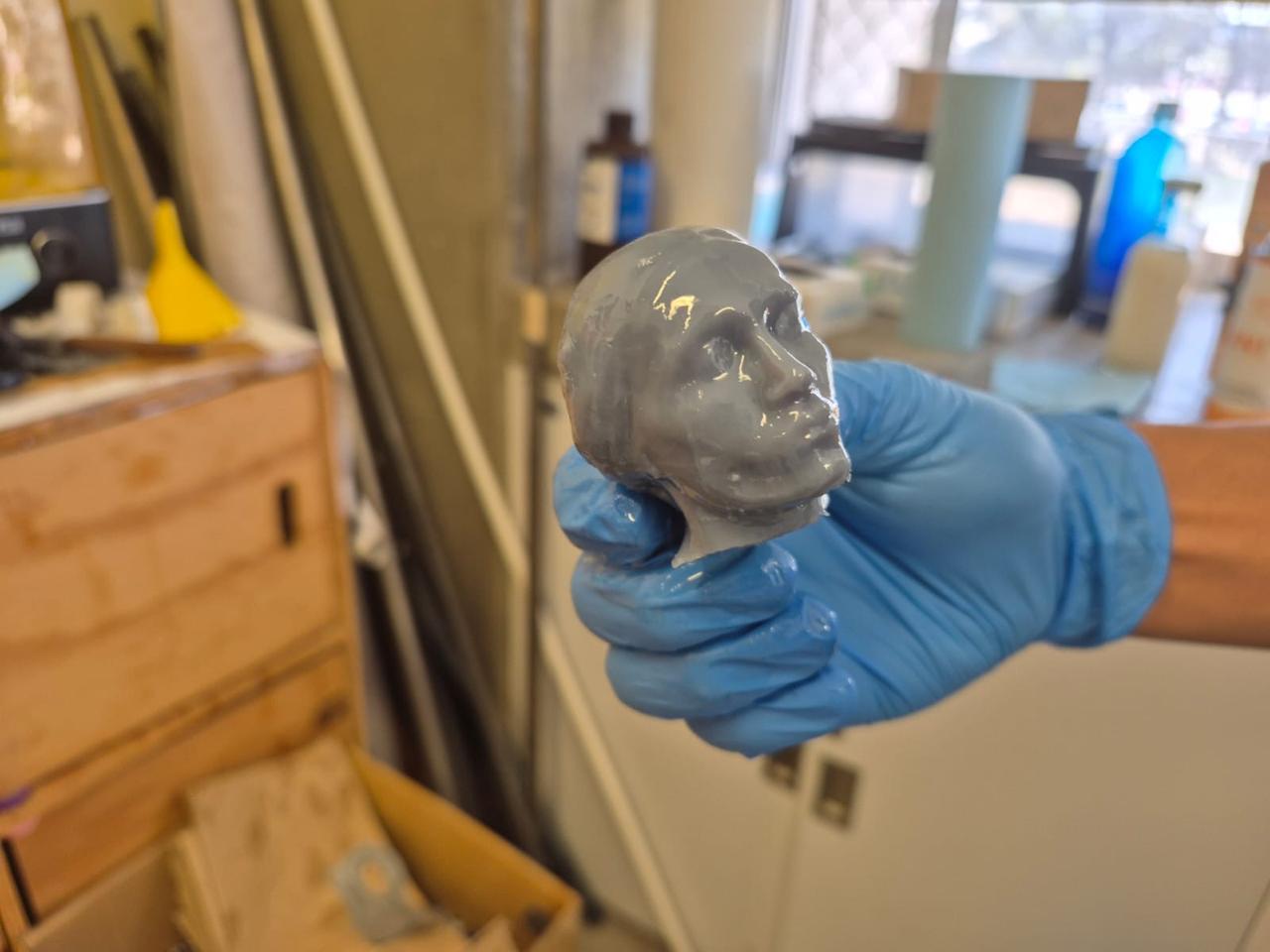
5. When the printing was finished, I gently removed my head with a spatula. My print consisted of 640 layers.
Steps
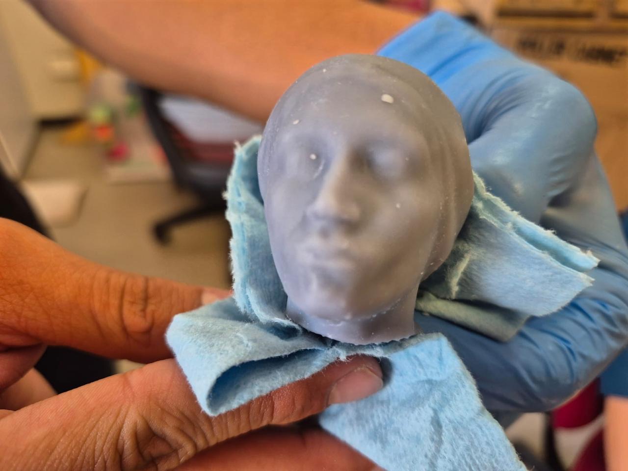
6. Finally I used an Anycubic Wash & Cure 3 to cure my piece and cleaned it using a paper towel and Isopropyl alcohol.
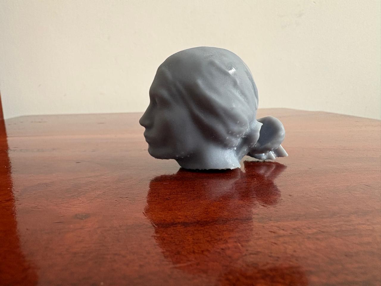
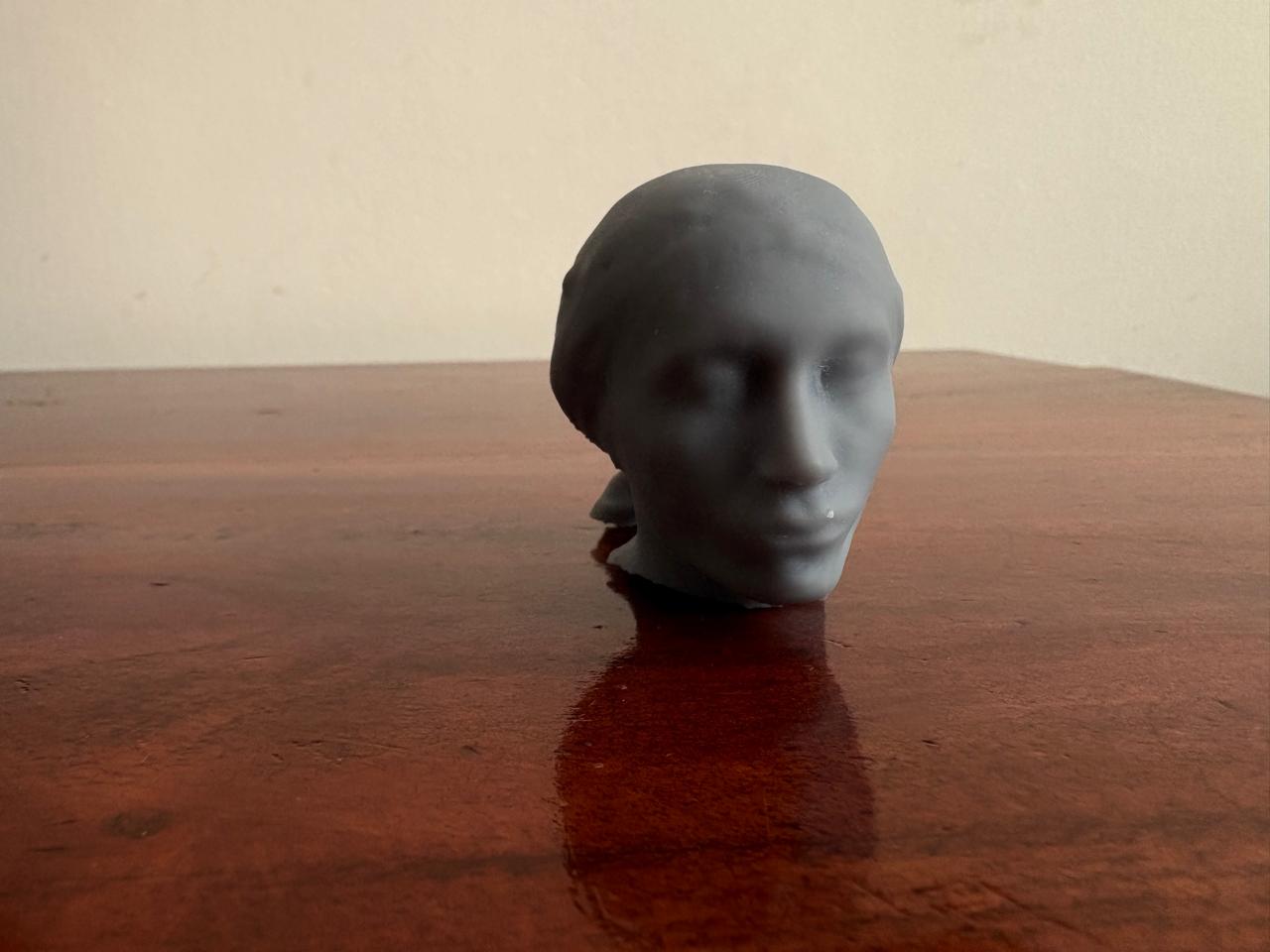
Results
Learning outcomes
This week, I learned a lot about 3D printing and its different types. I was not aware that ISO had classified 3D printing technologies into seven categories. I also learned how complex resin printing can be. It was my first time using this type of printer, and one of my prints failed due to poor adhesion to the build plate. Additionally, the cleaning process is quite tedious, although the results are highly accurate.
I also believe that 3D scanning is a remarkable tool for accurately replicating real structures. Its application in museums could be extremely valuable for the preservation of statues and historical artifacts.
When comparing filament printing and resin printing, I think both technologies have their own strengths and weaknesses. However, resin printing offers superior surface quality and detail, while filament printing is better suited for producing stronger and more durable structures.
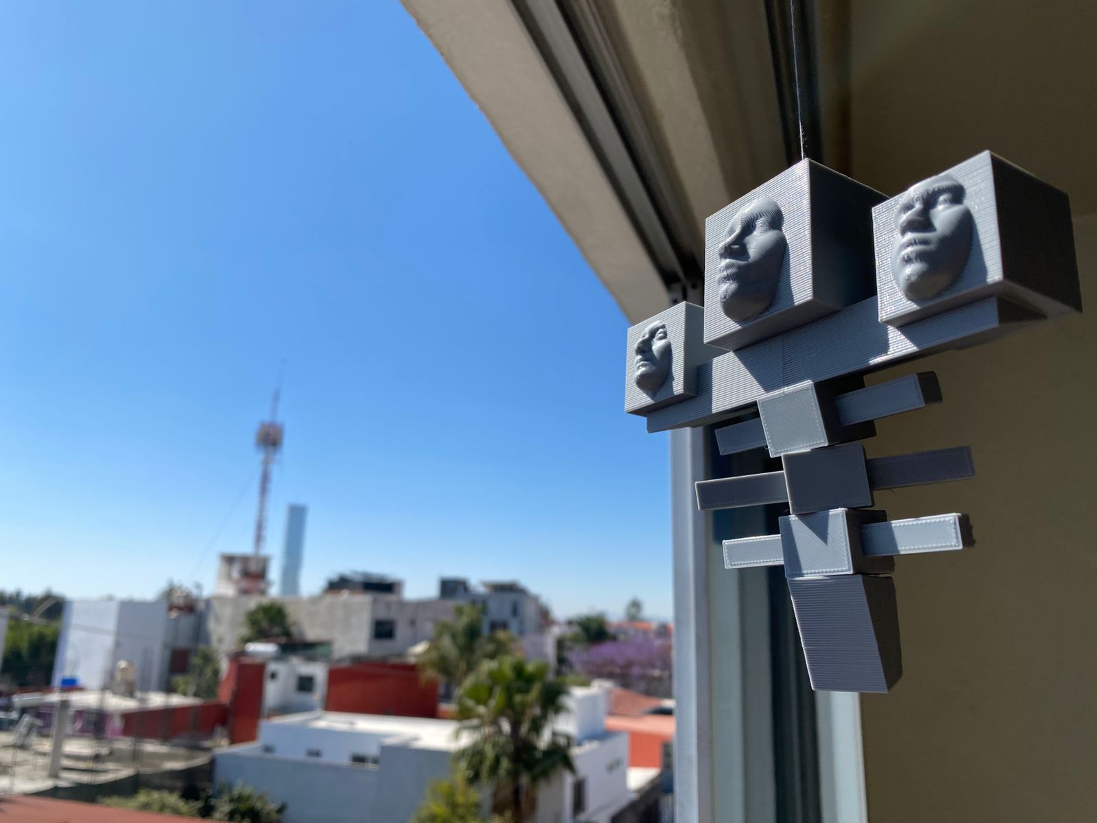
EXTRA. Wither
I scanned my face with my FAB friends and we decided to design this marvel of the new era: