Week 4: Embedded programming

This week, the task was to program a code using a microcontroller and read the datasheet of at least one microcontroller.
Our group assignment is this Week 5. It is worth a watch ;).

Datasheet

A datasheet in electronics is a technical document provided by manufacturers that details the specifications, functionality, pinout, and physical characteristics of a component. It acts as a guide for engineers to design reliable circuits by defining operating parameters, electrical characteristics, and maximum ratings.

One of the assignments for this week was browse through the data sheet for a microcontroller. A microcontroller unit (MCU) is essentially a small computer on a single chip. It is designed to manage specific tasks within an embedded system without requiring a complex operating system. I chose the ESP32 WROOM 32 by Espressif Systems and a Raspberry Pi Pico by Raspberry Pi.

Classification of Microcontrollers by Number of Bits

Bit: Is the smallest unit of data in electronics and computing, representing a single binary value of either 0 or 1. It acts as the fundamental building block for all digital information, representing logical states like on/off, true/false, or high/low voltage.

  • 8-bit Microcontrollers: Performs operations on 8 bits at a time. Ideal for basic simple tasks, such as timers, sensors, and motor control.
  • 16-bit Microcontrollers: Performs operations on 16 bits at a time. They are ideal for real-time control, precision measurement and industrial applications.
  • 32-bit Microcontrollers: Performs operations on 32 bits at a time. They offer high-performance processing, large memory addressing, and advanced peripherals, making them ideal for complex, power-efficient applications like IoT and industrial control.

Classification of Microcontrollers by Memory

  • Embedded Memory Microcontroller: Is a compact, single-chip computer that integrates all the necesary components. integrating a processor core, program memory (Flash/ROM), data memory (SRAM), and peripherals.
  • External Memory Microcontroller: Is a compact chip without on-chip integrated memory. It requires external program memory (Flash/ROM) and data memory (SRAM).

ESP32 WROOM 32

Feature

ESP32 WROOM 32

ROM

448 KB

SRAM

520 KB

SRAM in RTC

8 KB

Wifi
  • 802.11b/g/n
  • Bit rate: 802.11n up to 150 Mbps
Bluetooth
  • Bluetooth V4.2 BR/EDR
  • Bluetooth LEspecification
Peripherals
  • Up to 32 GPIOs.
  • SD card, UART, SPI, SDIO, I2C, LED PWM, Motor PWM, I2S, IR, pulse counter, GPIO, capacitive touch sensor, ADC, DAC, TWAI® (compatible with ISO 11898-1, i.e. CAN Specification 2.0)
Analog Inputs

18 Analog enabled pins

Operating Conditions
  • Operating voltage/Power supply: 3.0 ~ 3.6 V
  • Operating ambient temperature: –40 ~ 85 °C

Pinout

Pinout
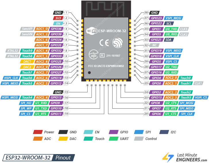
Power: These are the power supply pins, such as 3V3, which provide the necessary voltage for the module to operate.
GND: Ground pins that act as the common reference point for the electrical circuit.
EN: The Enable pin, used to boot, reset, or disable the chip.
GPIO: General Purpose Input/Output pins that can be programmed to act as either digital inputs or outputs.
SPI: Serial Peripheral Interface pins that are high-speed communication protocols for external devices like SD cards or displays.
I2C: Serial Data (SDA) and Serial Clock (SCL). These pins allow microcontrollers to connect to multiple sensors or devices simultaneously using a master-slave architecture.
DAC: Digital-to-Analog Converters used to output an analog voltage signal from the microcontroller.
Touch: Capacitive touch sensors that can detect human touch on conductive surfaces without mechanical buttons.
UART: Universal Asynchronous Receiver-Transmitter pins, typically used for serial communication with a PC or other microcontrollers.
Control: Pins used for specific internal system functions or clock signals.

Programming in C++

What is C++?

C++ is a high-level, general-purpose programming language created by Bjarne Stroustrup in 1979 as an extension of the C programming language. It is often described as "C with Classes," designed to provide the efficiency of low-level coding with the power of modern abstractions.

CPP

What is Wokwi?

Wokwi is an online platform that allows you to design, program, and simulate electronic projects, all from your web browser. It is perfect for learning electronics and programming, as well as for experienced developers looking for a practical and versatile simulation environment.

CPP

Wokwi

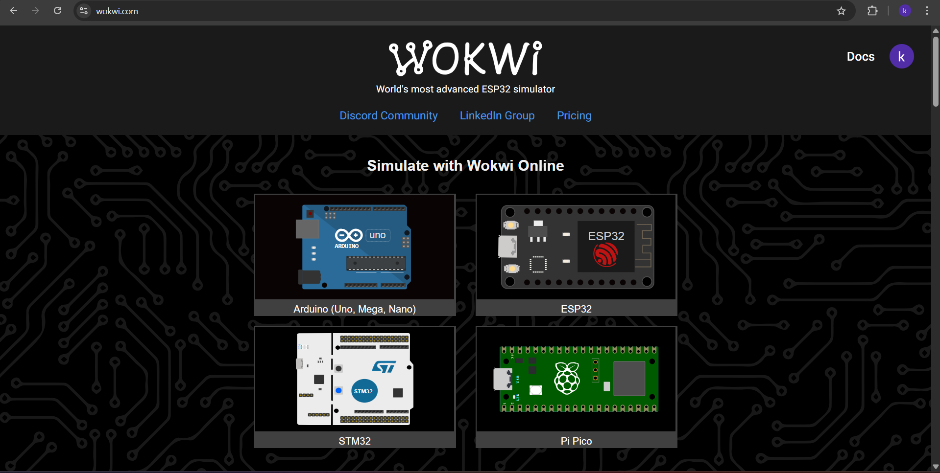
To use Wokwi, first we have to enter the site Wokwi.

Then we have to choose our Microcontroller. In this case I chose the ESP32.
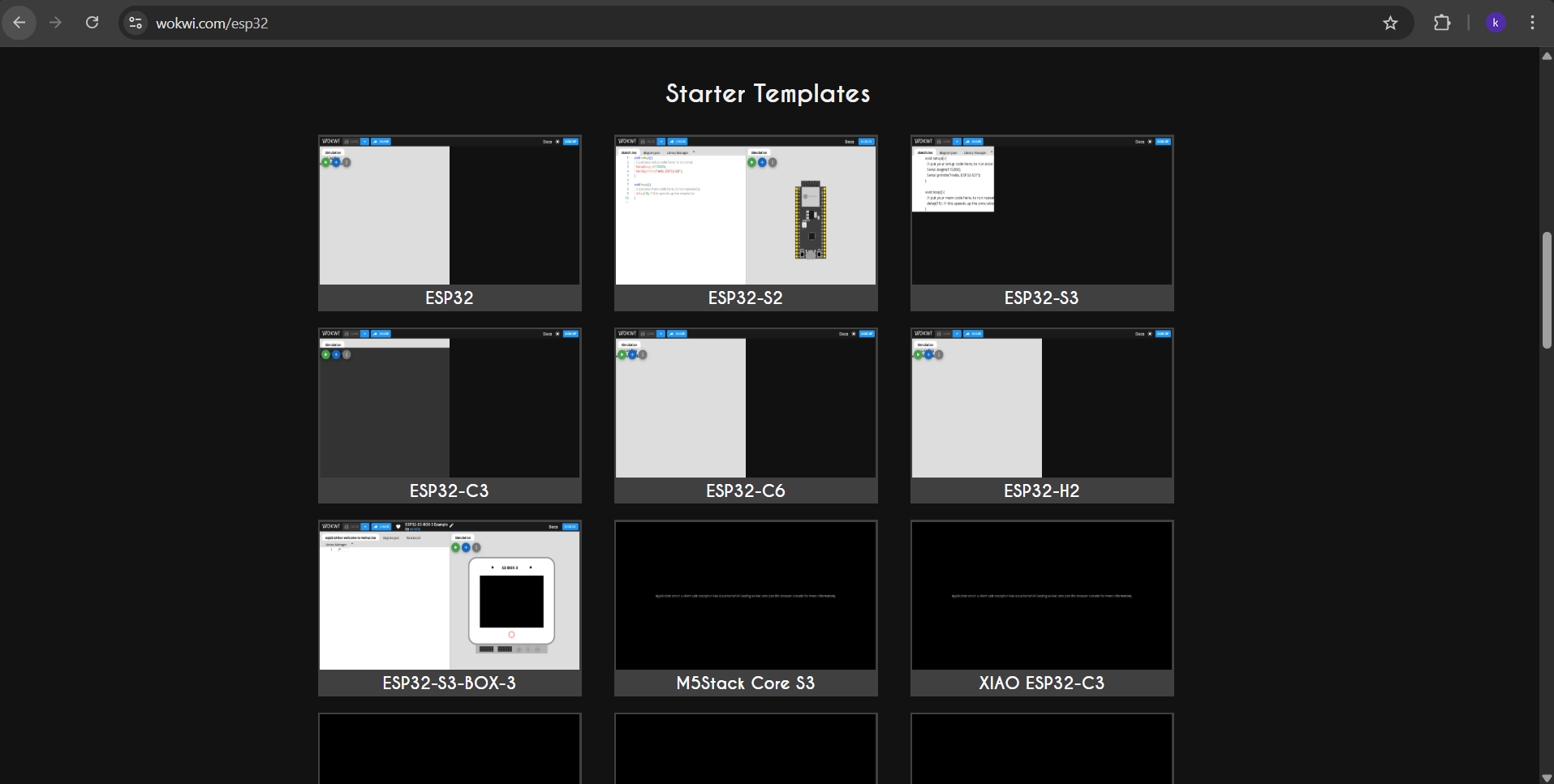
Fab termi

Wokwi

After choosing the ESP32, a menu will be displayed. In that menu we can choose between the different ESP32 models and different projects. I selected the generic version of ESP32.

Fab termi

Wokwi

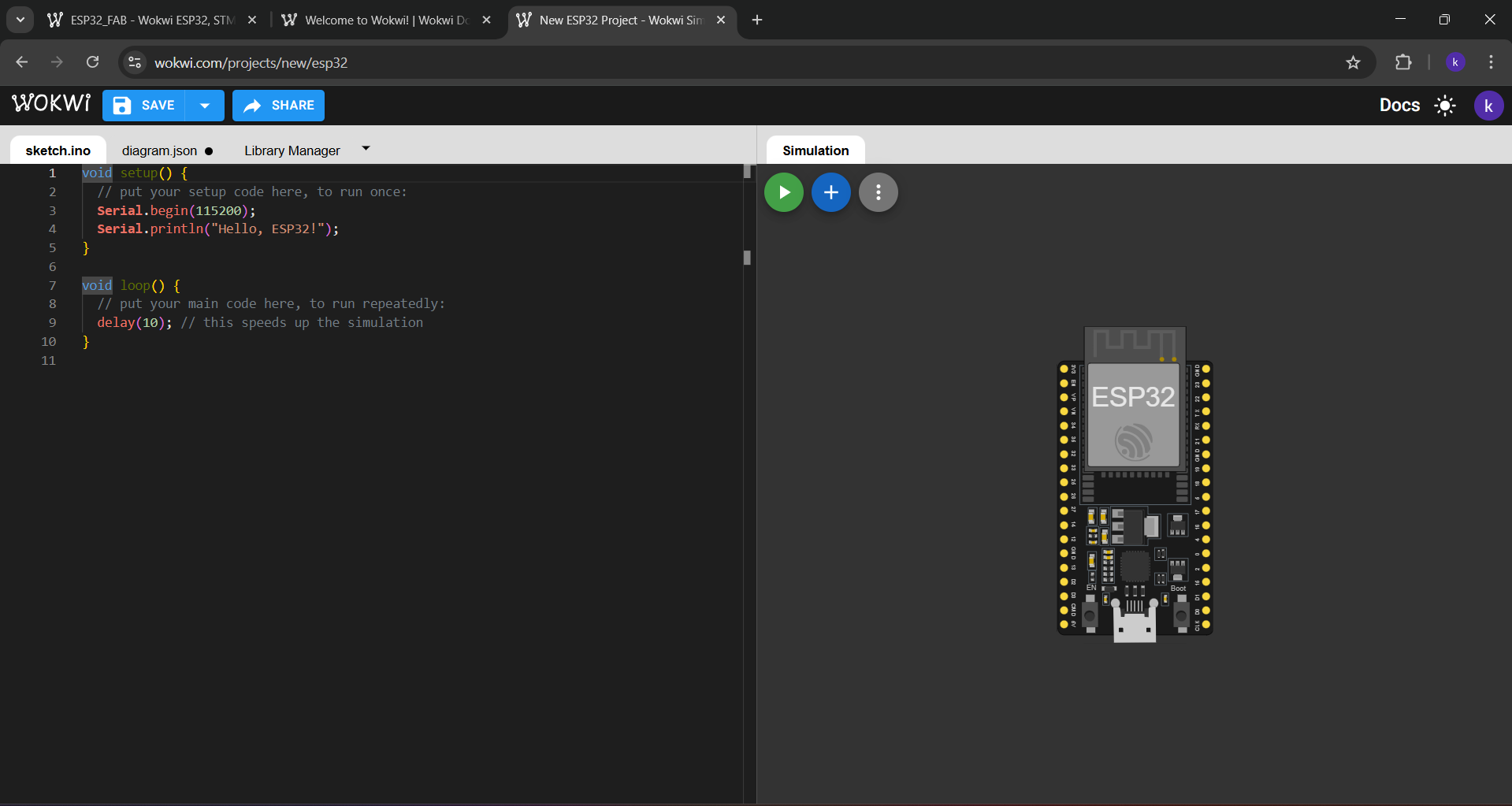
In the ESP32 project, a new page will be deployed. There is the place where we can upload our code and in the right section we can simulate our code by adding components to our microcontroller. The programming language we can use will depend on the microcontroller we choose. In this case, it will be C++

Fab termi

Wokwi

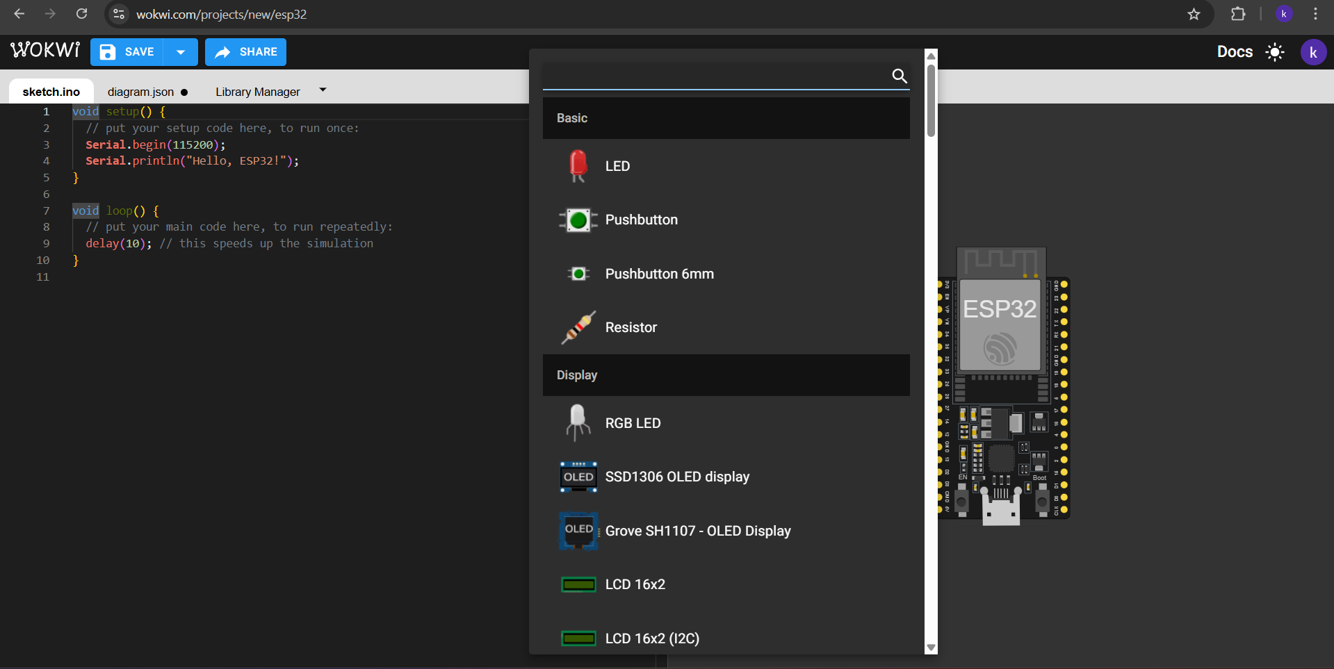
To add components to our microcontroller simulator we have to click in the + symbol blue button in the top of that section. There we have a large list of components we can insert, like LEDs, Buttons, resistors, etc.

Fab termi

Wokwi

After inserting the components in the simulation section, We can connect them by clicking on their pins and connecting them to the microcontroller or between each other.

Finally, to simulate we must click green button next to the + button. Our code will compile and we will see if it works or if we did something wrong.

My code

My code consists of turning on three LEDs in sequence and starting a timer each time one turns on to measure the time between the LED lighting up and the button being pressed. During the Development of my code I was assisted by ChatGPT to understand the ESP32 internal timer and to be able to register big numbers.

Code


                                            // ---------- Pins ----------
                                            const int ledPins[3] = {16, 17, 18};
                                            const int btnPins[3] = {13, 12, 14};

                                            // ---------- Time ----------
                                            hw_timer_t *timer = NULL;
                                            volatile unsigned long tiempo = 0; // ms

                                            // ---------- Control ----------
                                            int status = 0;
                                            bool waiting = false;

                                            // ---------- Interruption ----------
                                            void IRAM_ATTR onTimer() {
                                            tiempo++; // 1 ms
                                            }

                                            // ---------- Setup ----------
                                            void setup() {
                                            Serial.begin(9600);

                                            // LEDs
                                            for (int i = 0; i < 3; i++) {
                                                pinMode(ledPins[i], OUTPUT);
                                                digitalWrite(ledPins[i], LOW);
                                            }

                                            // Buttons
                                            for (int i = 0; i < 3; i++) {
                                                pinMode(btnPins[i], INPUT_PULLUP);
                                            }

                                            // ---------- Timer ----------
                                            timer = timerBegin(1000000);
                                            timerAttachInterrupt(timer, &onTimer);
                                            timerAlarm(timer, 1000, true, 0);
                                            timerStart(timer);

                                            iniciateLED();
                                            }

                                            // ---------- Loop ----------
                                            void loop() {
                                            if (waiting) {
                                                if (digitalRead(btnPins[status]) == LOW) {
                                                waiting = false;
                                                Serial.print("LED ");
                                                Serial.print(status + 1);
                                                Serial.print(" -> Tiempo: ");
                                                Serial.print(tiempo);
                                                Serial.println(" ms");
                                                delay(300);
                                                nextLED();
                                                }
                                            }
                                            }

                                            // ---------- Functions ----------
                                            void iniciateLED() {
                                            turnOff();
                                            tiempo = 0;
                                            digitalWrite(ledPins[status], HIGH);
                                            waiting = true;
                                            Serial.print("LED ");
                                            Serial.print(status + 1);
                                            Serial.println(" encendido...");
                                            }

                                            void nextLED() {
                                            status++;
                                            // If LED number 3 already ended:
                                            if (status >= 3) {
                                                waiting = false; // NO MORE BUTTONS LEFT
                                                turnOff(); // Turn off LEDs
                                                Serial.println("---- Cicle ended ----");
                                                return;
                                            }

                                            iniciateLED();
                                            }

                                            void turnOff() {
                                            for (int i = 0; i < 3; i++) {
                                                digitalWrite(ledPins[i], LOW);
                                            }
                                            }
                                        

                                            // ---------- Pins ----------
                                            const int ledPins[3] = {16, 17, 18};
                                            const int btnPins[3] = {13, 12, 14};
                                        
1. First, this part declares the pins where my LEDs and my buttons will be. It also relates each LED with each button.
const defines my variable as a constant. int defines my variable as an integer value. [3] defines that my array has 3 spaces, and {} assignates each one of them to one of the spaces my array has.

                                            // ---------- Time ----------
                                            hw_timer_t *timer = NULL;
                                            volatile unsigned long tiempo = 0; // ms

                                        
2. Then I declared the timer and started the time variable.
hw_timer_t is one of the internal watches of the ESP32.
*timer is a pointer where a timer will go. That timer will be declared in the setup(). NULL indicates that there isn't anything for now.
volatile indicates that a variable is prolly to change.unsigned long is for storage big numbers. tiempo = 0 is my registered time variable that for begining is equal to 0.

                                           // ---------- Control ----------
                                           int status = 0;
                                           bool waiting = false;
                                        
3. Next, I declared the control variables to know which LED I would be on and if there are more LEDs after that..
int status = 0 is to know in which of the 3 states (LEDs) I am, it starts at 0 because at the beginig it isn't in any state. bool indicates that a variable is one state or another, true or false. bool waiting = false starts at false because it isn't waiting for any LED yet.

                                           // ---------- Interruption ----------
                                            void IRAM_ATTR onTimer() {
                                            tiempo++; // 1 ms
                                            }

                                            // ---------- Setup ----------
                                            void setup() {
                                            Serial.begin(9600);

                                            // LEDs
                                            for (int i = 0; i < 3; i++) {
                                                pinMode(ledPins[i], OUTPUT);
                                                digitalWrite(ledPins[i], LOW);
                                            }

                                            // Buttons
                                            for (int i = 0; i < 3; i++) {
                                                pinMode(btnPins[i], INPUT_PULLUP);
                                            }

                                        
4. Then I setted an interruption for ensuring maximum speed and prevent flash cache missing. Also, started the Serial and declared the Output of my LEDS and buttons as LOW.
IRAM_ATTR onTimer() tells to a function to use or to be in the Internal RAM of the ESP32. tiempo++ tells that every time the timer is working, my time variable will increment its value 1 by 1. Serial.begin(9600) activates the Serial, the communication with the PC.  // LEDs
 for (int i = 0; i < 3; i++) {
  pinMode(ledPins[i], OUTPUT);
  digitalWrite(ledPins[i], LOW);
 }
Declares each LED, while i value is less than 3, a led will be declared. Instead of declaring them indivually, the "for" does it all at the same time.  // Buttons
 for (int i = 0; i < 3; i++) {
  pinMode(btnPins[i], INPUT_PULLUP);
 }
The same happends with the buttons, INPUT_PULLUP declares the button state as LOW.

                                        // ---------- Timer ----------
                                            timer = timerBegin(1000000);
                                            timerAttachInterrupt(timer, &onTimer);
                                            timerAlarm(timer, 1000, true, 0);
                                            timerStart(timer);
                                         
5. Afterwards, I created the timer, the interrupt, and the alarm.
timerBegin(1000000) sets the timer at a MHz frequency, because at this working speed, every cycle will last 1 microsecond.
timerAttachInterrupt(timer, &onTimer) when the timer starts it calls &onTimer. timerAlarm(timer, 1000, true, 0) defines the timer in microseconds and establis it as a repetitive task. timerStart(timer) starts the timer.

                                        // ---------- Loop ----------
                                            void loop() {
                                            if (waiting) {
                                                if (digitalRead(btnPins[status]) == LOW) {
                                                waiting = false;
                                                Serial.print("LED ");
                                                Serial.print(status + 1);
                                                Serial.print(" -> Time: ");
                                                Serial.print(tiempo);
                                                Serial.println(" ms");
                                                delay(300);
                                                nextLED();
                                                }
                                            }
                                            }
                                         
6. This block is to print counted in the Serial Monitor.
void loop is a function that executes a code repeatedly in an infinite loop after void setup() finishes. Serial.print is a function used to send data from a microcontroller to a computer via USB, allowing it to be viewed in the Serial Monitor. if (waiting){} If it is waiting for a button to be pressed, it will ensure that it detects whether the buttons are off. if (digitalRead(btnPins[status])) if the buttons asre off, then the program will "LED status + 1 Time: tiempo ms". delay()is a function in Arduino to pause the program for a specified amount of time in milliseconds. nextLED() To jump to the next led.

                                            // ---------- Functions ----------
                                            void iniciateLED() {
                                            turnOff();
                                            tiempo = 0;
                                            digitalWrite(ledPins[status], HIGHHIGH);
                                            waiting = true;
                                            Serial.print("LED ");
                                            Serial.print(status + 1);
                                            Serial.println(" encendido...");
                                            }
                                        
7. This void is the responsable of turning on the LEDs.
void iniciateLED(){} is to turn on the LED. turnoOff() is to turn off the LEDs. tiempo = 0 Defines my timer at 0 every time it starts so it can count the time of each LED. digitalWrite(ledPins[status],HIGH) Set my LED to High so that it turns on. waiting = true Setting waiting as true lets my program to wait for the next LED. "LED status + 1 encendido..." To tell the led is on.

                                            void nextLED() {
                                            status++;
                                            // If LED number 3 already ended:
                                            if (status >= 3) {
                                                waiting = false; // NO MORE BUTTONS LEFT
                                                turnOff(); // Turn off LEDs
                                                Serial.println("---- Cicle ended ----");
                                                return;
                                            }
                                            iniciateLED();
                                            }
                                        
8. This void is the responsable of jumping into the next LED.
if (status >=3){}{waiting = false...} this sets the waiting variable as false to stop waiting for more LEDs. turnoOff() is to turn off the LEDs. ("---- Cicle ended ----") To tell there are no more LEDs tu turn on. iniciateLED() To iniiciate the next LED, in case there is still one.

                                            void turnOff() {
                                            for (int i = 0; i < 3; i++) {
                                                digitalWrite(ledPins[i], LOW);
                                            }
                                            }
                                        
9. This void is the responsable of turning off the LEDs.
for (int i = 0; i < 3; i++) this sets the times my LEDs will turn off, while they are less than 3, they'll turn off.

ARDUDINO IDE

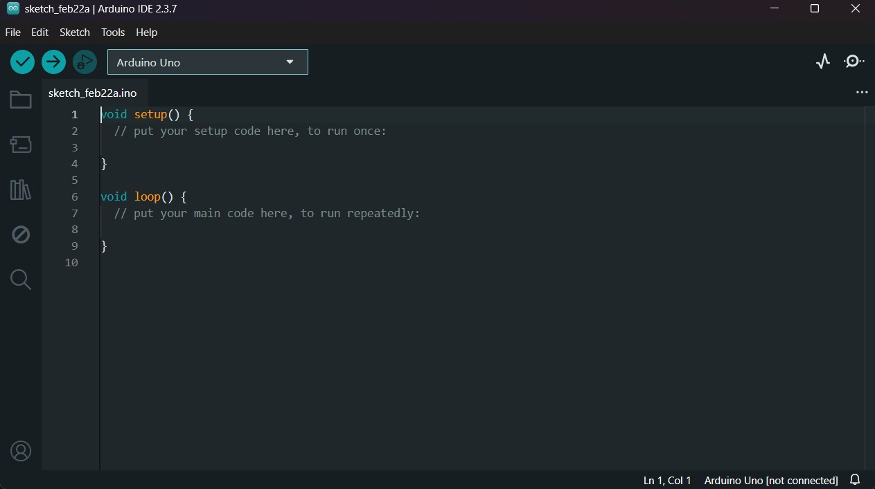
To upload the code into an ESP32 WROOM 32 I used ARDUINO IDE. ARDUINO IDE is a free, open-source application for Windows, macOS, and Linux, used to write, compile, and upload code to Arduino boards. It provides a text editor, toolbar, and serial monitor, supporting C/C++ to create ".ino" sketch files for controlling microcontrollers.

AIDE

Download

To download Arduino IDE, we must click this link and follow the steps descrived in the official page.

Shortly, what we have to do is to download the installer for our operating system (Windows, Mac Os, Linux.) and execute it.

ESP32 Board

After installing ARDUINO IDE, we must open a new sketch. To do that we have to click in File located in the top menu and select New sketch.

sketch

ESP32 Board

Then go to the left menu and press the second icon in descendent order, it is the Board Manager.
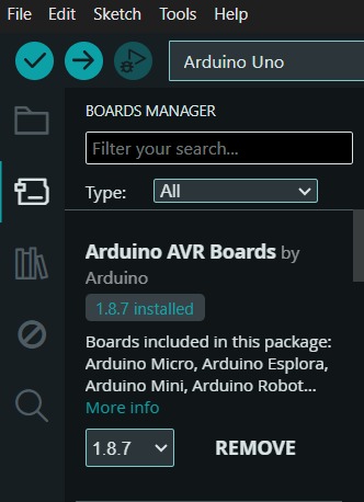
BM

ESP32 Board

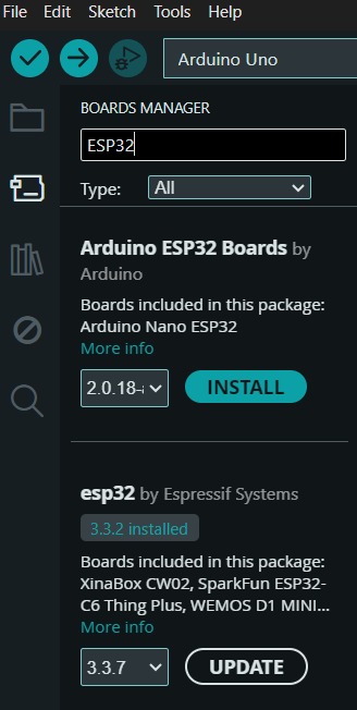
In the Board Manager, we must write in the searcher this: ESP32. And install the Espressif version.

BM

Uploading

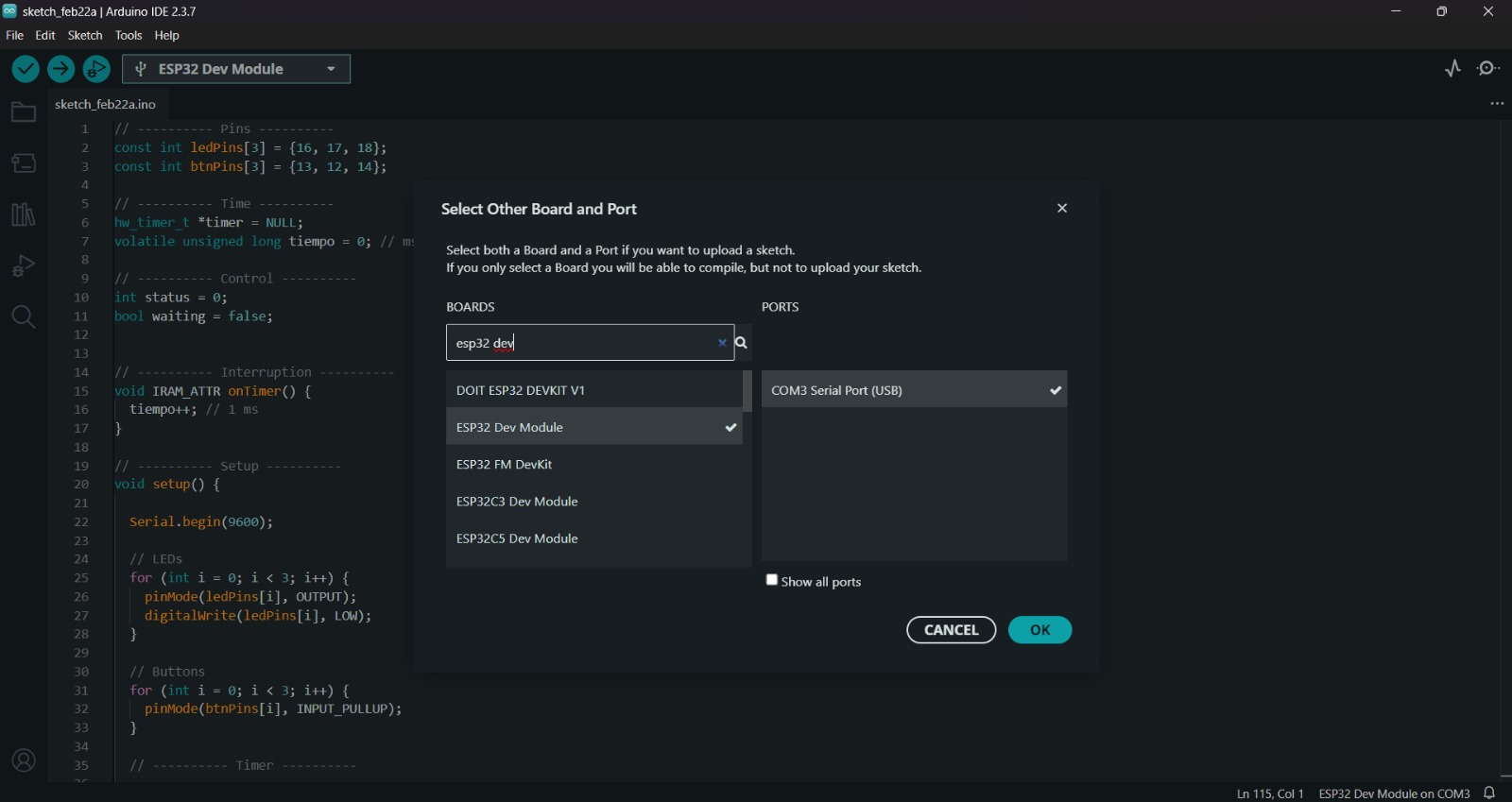
After installing the ESP32 Board, we must click on the tab that says select board and write ESP32 Dev Module, then select the PORT where our microcontroller is connected and upload the information.

Up_1 Up_2

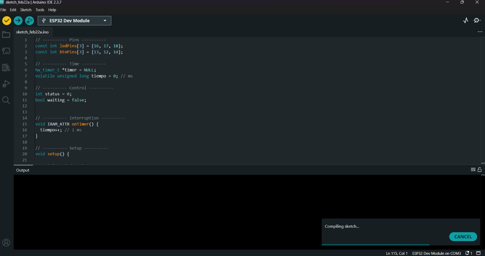
Before uploading our code to the microcontroller we should use the verify tool, that compiles the code before uploading it in order to detect mistakes or problems. The verify tool is the one in the top with the check.

Uploading

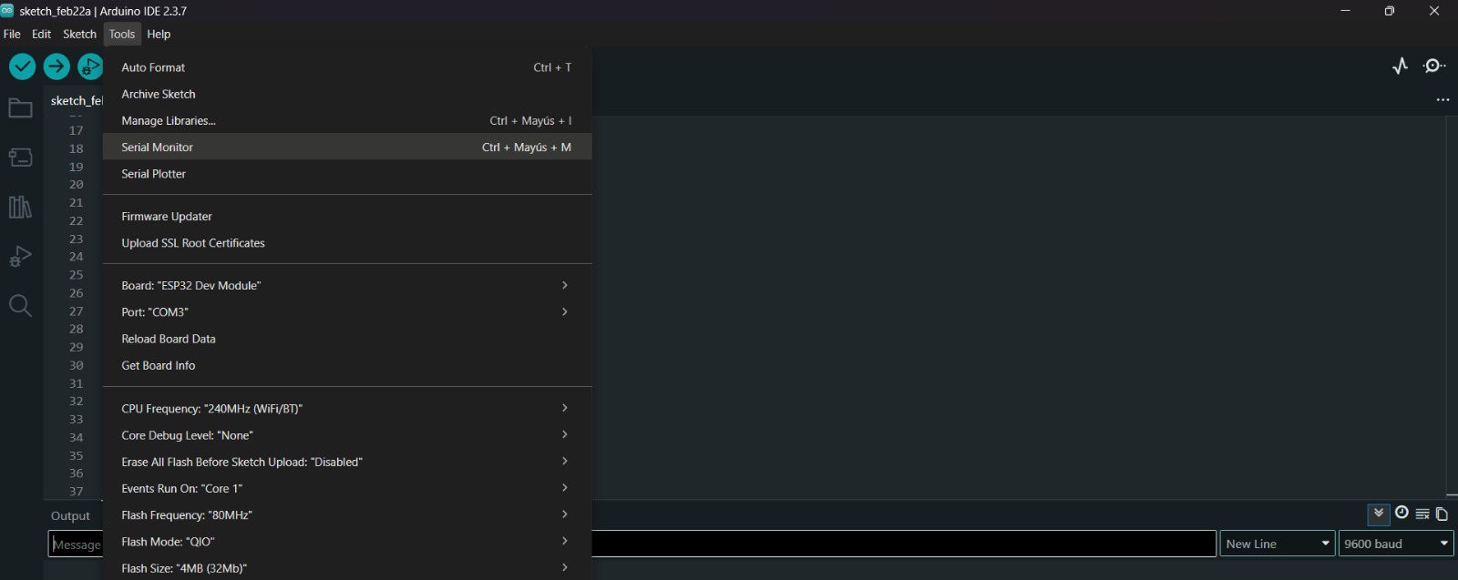
To get the Serial Monitor, we must click on Tools un in the top menu and select Serial Monitor.

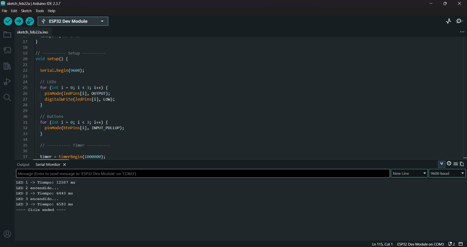
Finally, to upload our code we must click the upload tool, that is the one with the arrow pointing to the right. If our code is right, it shall compile.

SM Up_3

Result

Programming in Python

What is Python?

Python is an interpreted, object-oriented, high-level programming language with dynamic semantics. Its high-level built in data structures, combined with dynamic typing and dynamic binding, make it very attractive for Rapid Application Development, as well as for use as a scripting or glue language to connect existing components together. Python's simple, easy to learn syntax emphasizes readability and therefore reduces the cost of program maintenance..

py

My Code

My code consists of turning on three LEDs in sequence and starting a timer each time one turns on to measure the time between the LED lighting up and the button being pressed.

My Code


                                            from machine import Pin
                                            import time

                                            # ---------- Pines ----------
                                            led_pins = [2, 4, 5]
                                            btn_pins = [26, 27, 28]

                                            # ---------- LEDs ----------
                                            leds = [Pin(p, Pin.OUT) for p in led_pins]

                                            # ---------- Botones (Pull-up) ----------
                                            buttons = [Pin(p, Pin.IN, Pin.PULL_UP) for p in btn_pins]

                                            # ---------- Control ----------
                                            estado = 0
                                            terminado = False


                                            # ---------- Funciones ----------

                                            def apagar_todo():
                                                for led in leds:
                                                    led.value(0)


                                            def iniciar_led(i):
                                                apagar_todo()
                                                leds[i].value(1)
                                                inicio = time.ticks_ms()
                                                print(f"LED {i+1} encendido...")
                                                return inicio


                                            # ---------- Programa principal ----------

                                            while not terminado:
                                                inicio = iniciar_led(estado)
                                                esperando = True

                                                while esperando:
                                                    # Botón presionado = LOW (0)
                                                    if buttons[estado].value() == 0:
                                                        tiempo = time.ticks_diff(time.ticks_ms(), inicio)
                                                        print(f"LED {estado+1} -> Tiempo: {tiempo} ms")
                                                        time.sleep(0.3)  # Antirebote
                                                        esperando = False

                                                estado += 1

                                                #  If ended
                                                if estado >= 3:
                                                    apagar_todo()
                                                    print("---- Ciclo terminado ----")
                                                    terminado = True
                                                

                                    from machine import Pin
                                    import time

                                    # ---------- Pines ----------
                                    led_pins = [2, 4, 5]
                                    btn_pins = [26, 27, 28]

                                    # ---------- LEDs & Buttons ----------
                                    leds = [Pin(p, Pin.OUT) for p in led_pins]
                                    buttons = [Pin(p, Pin.IN, Pin.PULL_UP) for p in btn_pins]
                                            
1. First, I import the libraries to control the hardware and time. Then, I define the pins for LEDs and buttons.
machine.Pin is the class used to control the GPIOs. Pin.PULL_UP sets the internal resistor so the button reads 0 when pressed.
[for p in pins] is a "List Comprehension", a fast way in Python to initialize all pins at once instead of doing it one by one.

                                    # ---------- Control ----------
                                    estado = 0
                                    terminado = False
                                            
2. Then I declared the control variables for the sequence logic.
estado = 0 keeps track of which LED/Button pair is currently active (0, 1, or 2).
terminado = False is a boolean flag that will stop the main loop once the full cycle is completed.

                                    def apagar_todo():
                                        for led in leds:
                                            led.value(0)

                                    def iniciar_led(i):
                                        apagar_todo()
                                        leds[i].value(1)
                                        inicio = time.ticks_ms()
                                        print(f"LED {i+1} encendido...")
                                        return inicio
                                            
3. These functions handle the LED behavior and timing.
apagar_todo() ensures no other LEDs remain on. led.value(0) sets the pin to LOW.
time.ticks_ms() captures the exact internal time in milliseconds when a LED turns on. This is our "start point" to calculate the reaction time.

                                    while not terminado:
                                        inicio = iniciar_led(estado)
                                        esperando = True

                                        while esperando:
                                            if buttons[estado].value() == 0:
                                                tiempo = time.ticks_diff(time.ticks_ms(), inicio)
                                                print(f"Time: {tiempo} ms")
                                                time.sleep(0.3)
                                                esperando = False
                                        
                                        estado += 1
                                        if estado >= 3:
                                            terminado = True
                                            
4. Finally, the main loop manages the sequence and user input.
while not terminado keeps the program running until the 3rd button is pressed.
time.ticks_diff() calculates the elapsed time since the LED turned on until the press.
time.sleep(0.3) acts as a software "debounce" to prevent multiple detections for a single press.

Learning outcomes

This week, I read several microcontroller datasheets and concluded that the ESP32-WROOM-32 chip is the best choice for my project due to its integrated Bluetooth and Wi-Fi capabilities, as well as its large number of analog and digital pins. I also returned to programming in C++ and Python after some time without practicing, which allowed me to refresh my understanding of both languages.


In my opinion, C++ offers better performance because the program is compiled and executed as a whole, whereas Python is interpreted line by line. This makes C++ more efficient for real-time and embedded applications, where speed and hardware control are essential. Additionally, C++ provides greater control over memory management and system resources, which is important when working with microcontrollers. On the other hand, Python is more intuitive and easier to read, allowing faster development and testing of ideas. For this reason, I see Python as an excellent tool for prototyping, while C++ is better suited for final embedded implementations.


Understanding the ESP32 timer was particularly challenging and required significant time to fully grasp. My goal is to use this timer for a timing application in my boxing project.

Files