
SYSTEM INTEGRATION
Individual assignments
- Integrate the final project system and document the development process
This week consisted of the organization and integration planning for the final project. To achieve this, I divided the project into different phases: Outputs, Inputs, 3D Print, Laser, Embedded Programming, and Interface and Application. These stages are extremely important to me because they allow me to fully complement and complete the project. During this week, I worked on the first two parts, which include 3D printing, laser cutting, and embedded programming, and these will allow me to complete the outputs and inputs sections.
What is System Integration?
System integration is the process of connecting different applications, physical components, or data so they can function as a coherent and coordinated system. It is also related to the way in which several systems are managed and organized to work together correctly.
Electronic Production
For the electronics section, I designed two boards: one for motor control and another as the main board, where the sensors and motors will be controlled. In other words, it is the brain of the robot.
First, I considered the board that would be used. In my case, I will need a XIAO ESP32C6. This board has Bluetooth and Wi-Fi capabilities, which I will use to control the robot. Likewise, I searched for the pinouts of the board. It was necessary to consider the number of pins available for connecting the sensors as well as the motor drivers. This microcontroller has the appropriate number of pins required for the complete system.
In addition, I added 10k resistors to the corresponding inputs for the sensors that will be used (SDA and SCL). Once the schematic was completed, the PCB design was created.
For my H-bridge, I used the TB67H450FNG,EL component, which allows me to control the motor. To determine the current that should pass through the H-bridge, the startup current was considered. In the case of the motors I am using, they can instantaneously reach up to 1.5 A. Since I am designing an H-bridge to control only one motor, I decided to leave a slightly higher current margin.
This is important to consider because the PCB design requires defining the trace sizes, since the amount of current that passes through a trace depends on its thickness. During Week 6, we learned how to calculate this thickness using the automatic calculator in KiCad, so I used it. The result obtained was 0.8 mm.
Therefore, in Altium I adjusted the preferred and allowed values for the traces. After that, I began the routing process. To change the units, press Q, which allowed me to switch the measurements to millimeters.
To create the outline of my H-bridge, I left free space to make a hole and connect it to the main board, which is the brain of the car. I also considered the tools I have available, so my trace width had to be 2 mm.
In the case of the driver, it was necessary to add capacitors to regulate voltage drops. In this way, I was able to complete the PCB design of the driver. In total, four drivers will be manufactured in order to independently control each motor.
Product Design
For the car design, it was important to first create a sketch of how I wanted the final result to look.
Once this was done, I used SolidWorks, since it is the program I am most comfortable using. The robot design first focused on the internal structure, so the following components were created:
- Gear motor
- Mecanum wheel
- Representation of the created PCBs
- Battery charger
Finally, the base and the outer casing were also designed. It is important to highlight that the base will be laser-cut, while the casing will be printed using PLA filament.
Each of the created parts can be printed correctly; however, before fully printing them, I will perform simple tests to compare the real measurements against the design dimensions. This will allow me to make modifications if necessary.

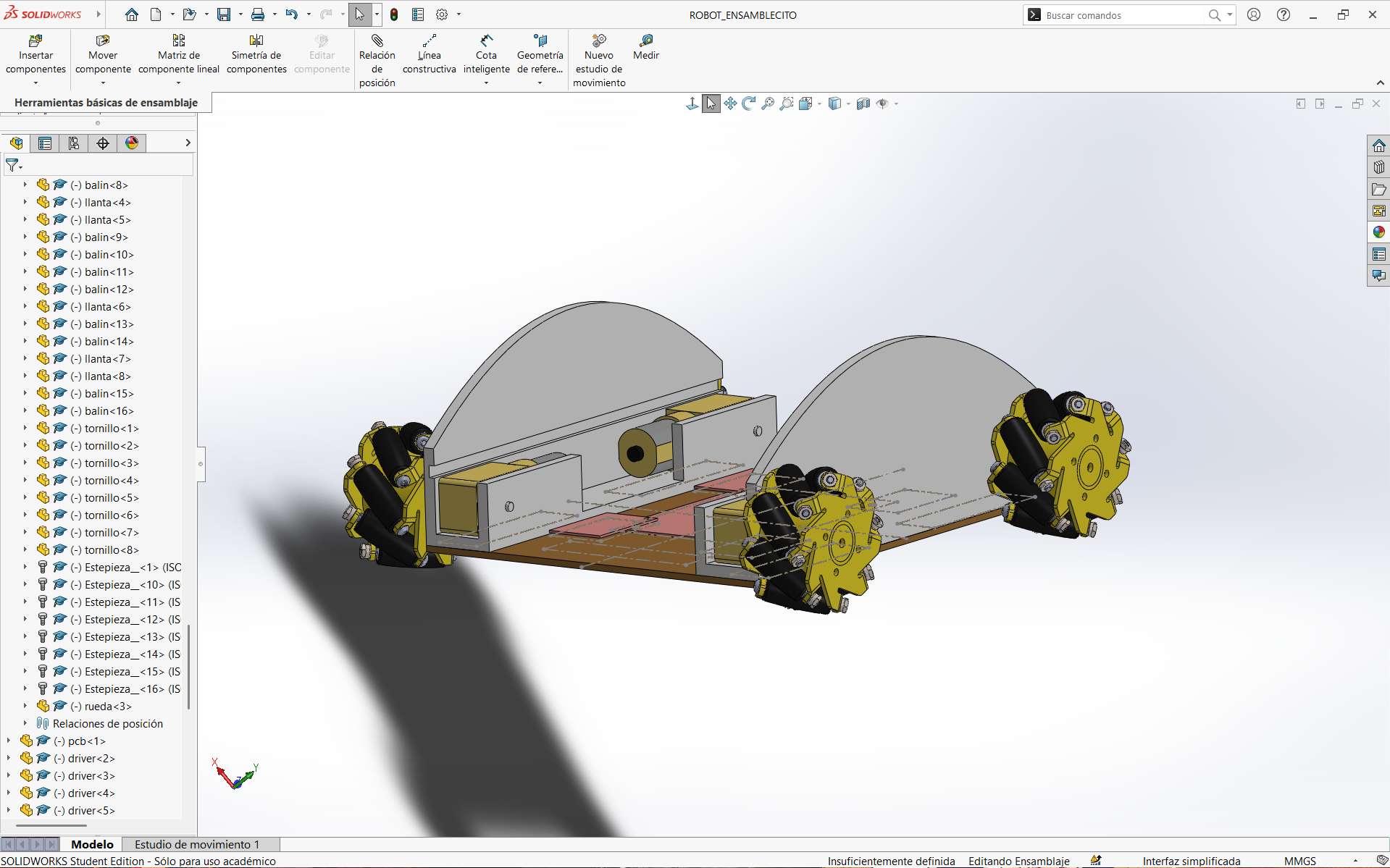
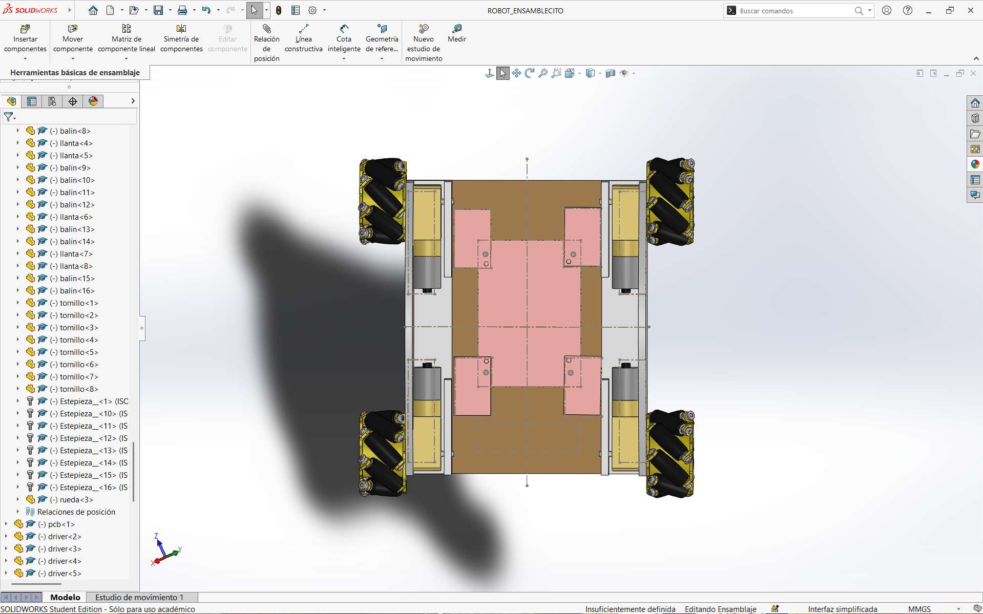
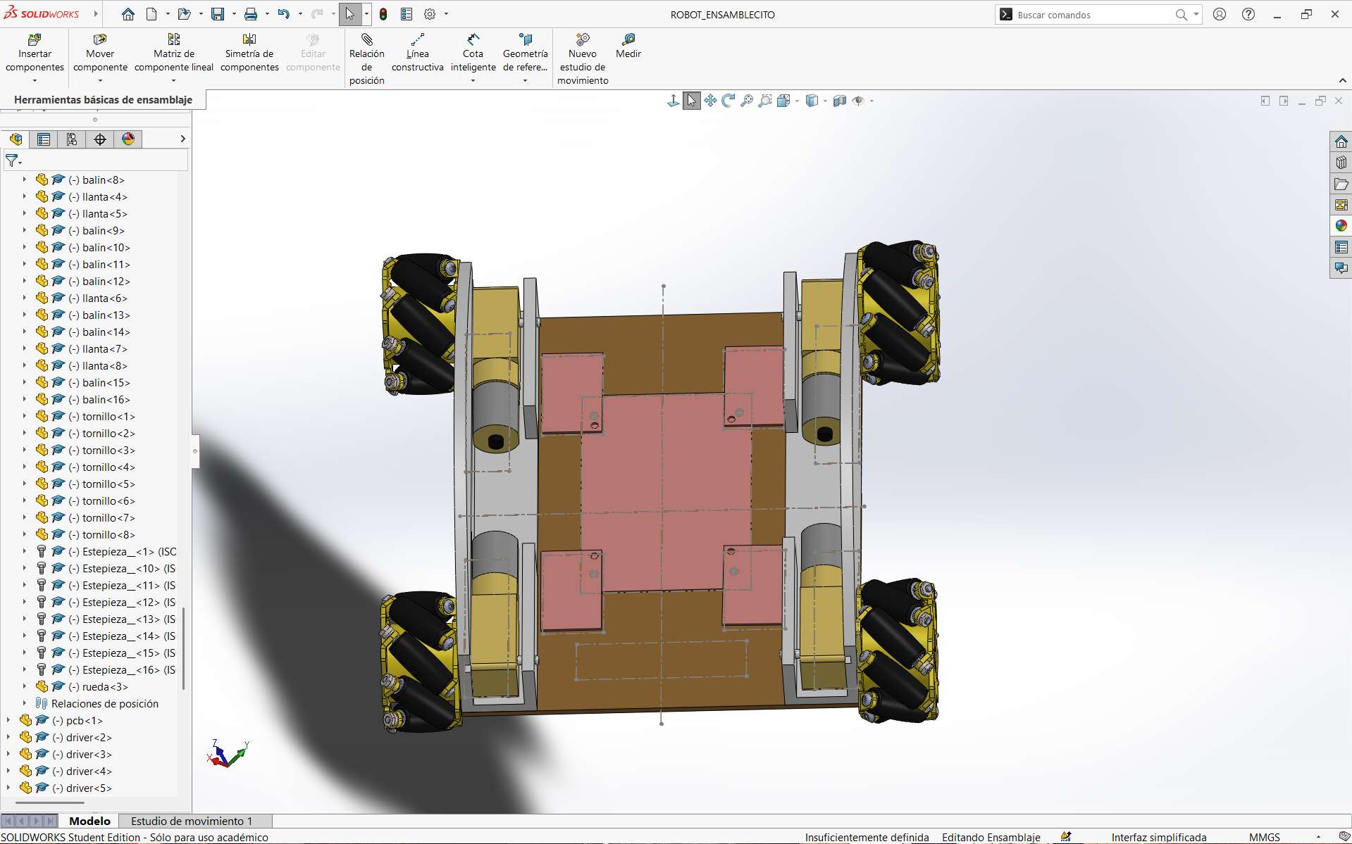
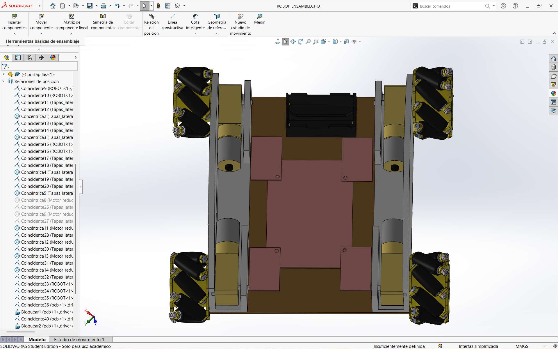
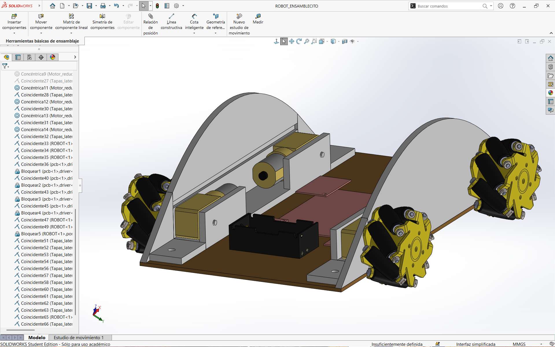
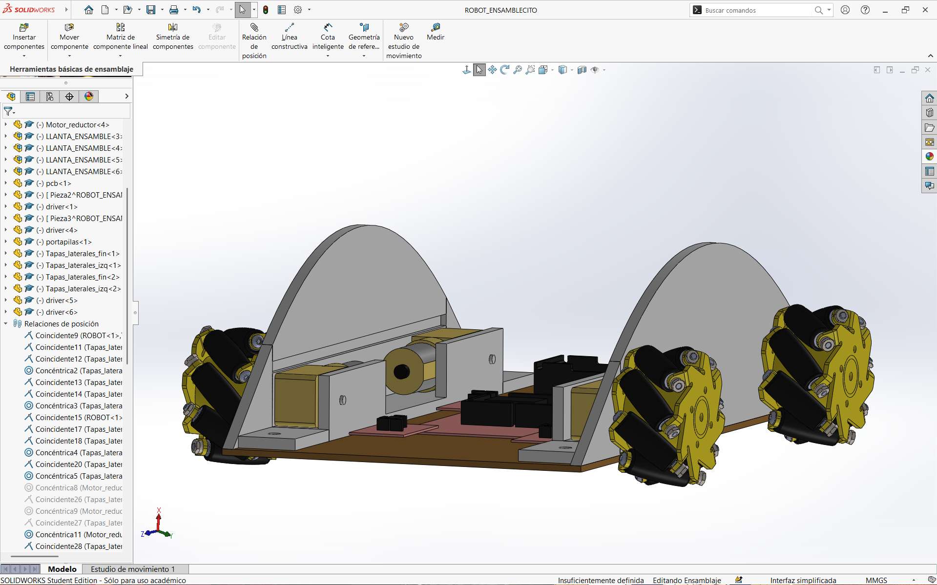
Once the components were completed, the wheel assembly process continued. This process took a little longer due to the number of small components that needed to be connected together. Once completed, this assembly was saved and inserted into the final robot assembly.
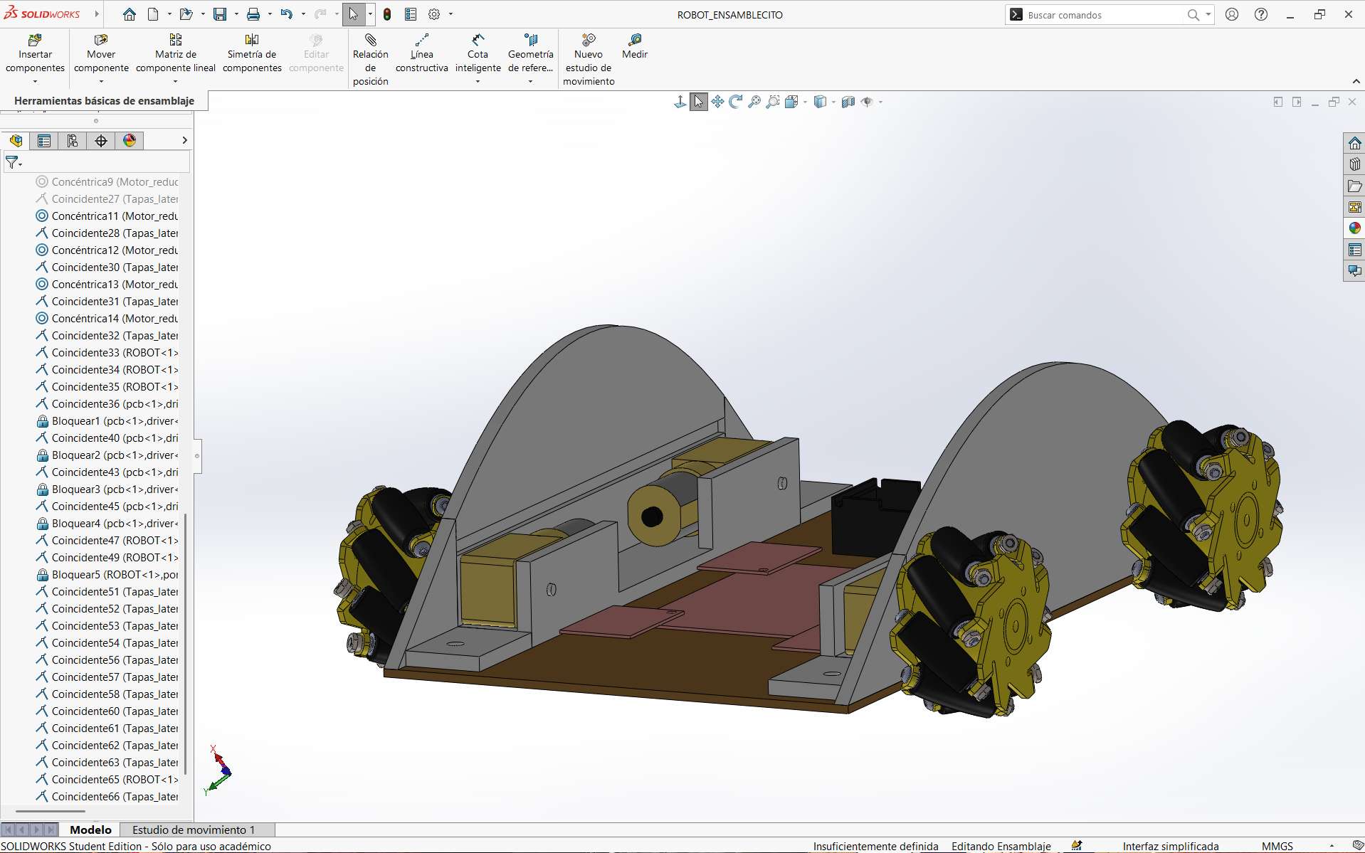
To fully complete the robot, different tools were used to modify and establish the positions of the components according to the project requirements. The options I used the most were concentricity, lock, and coincidence. In this way, I was able to fully complete the assembly.
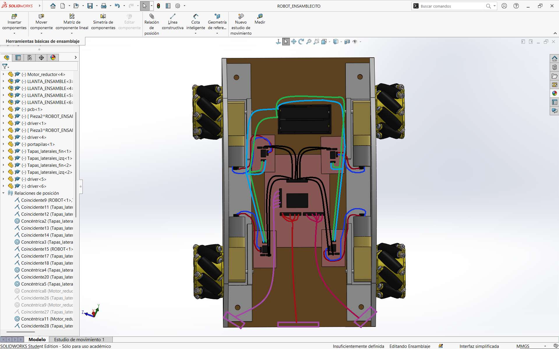
These are some pictures of the assembly created in SolidWorks, representing what is intended to be delivered as the final product.
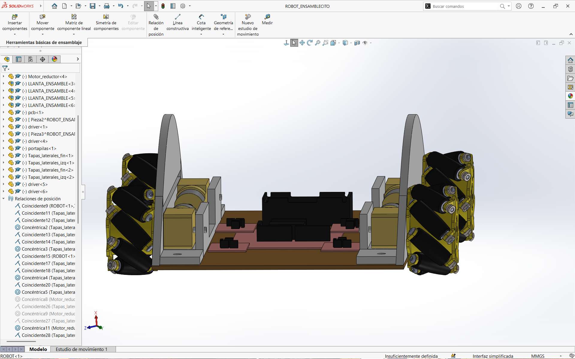
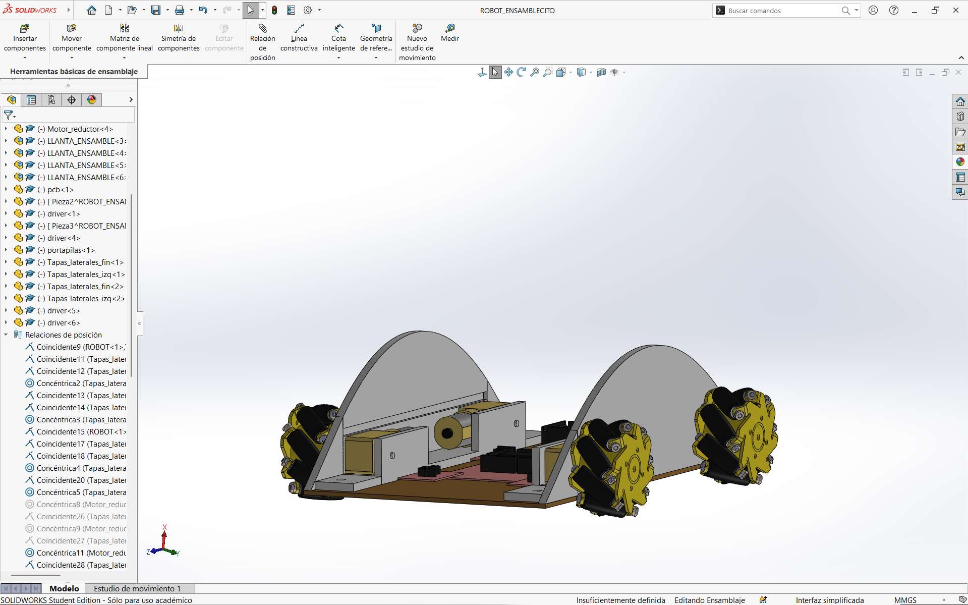
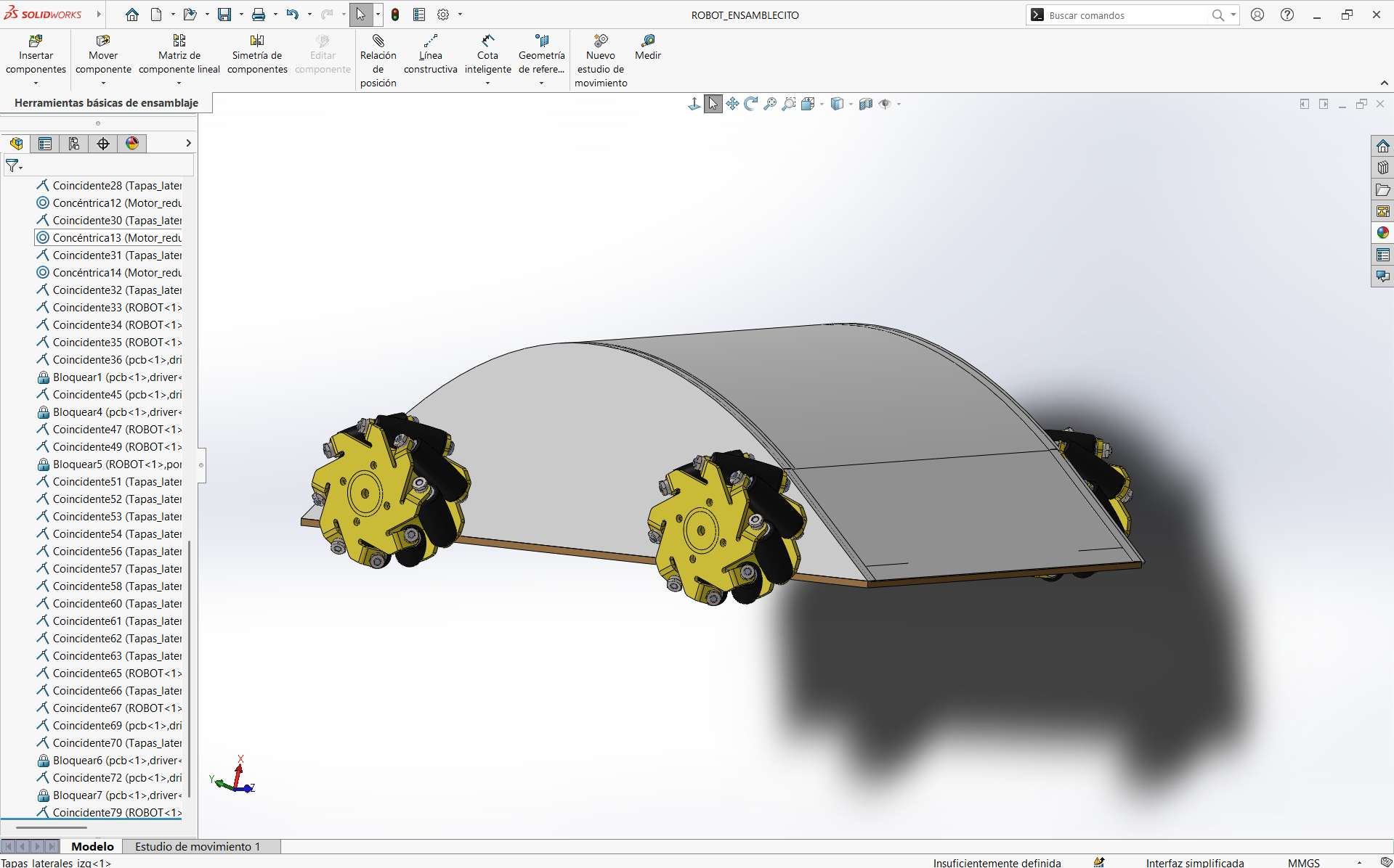
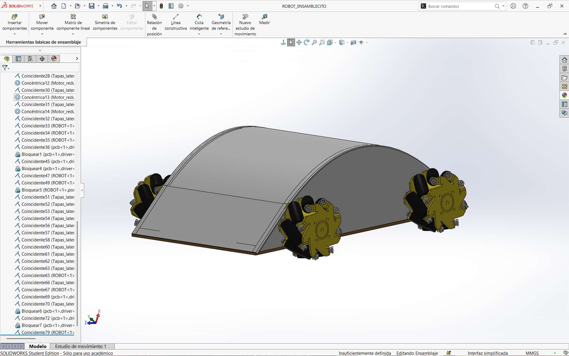
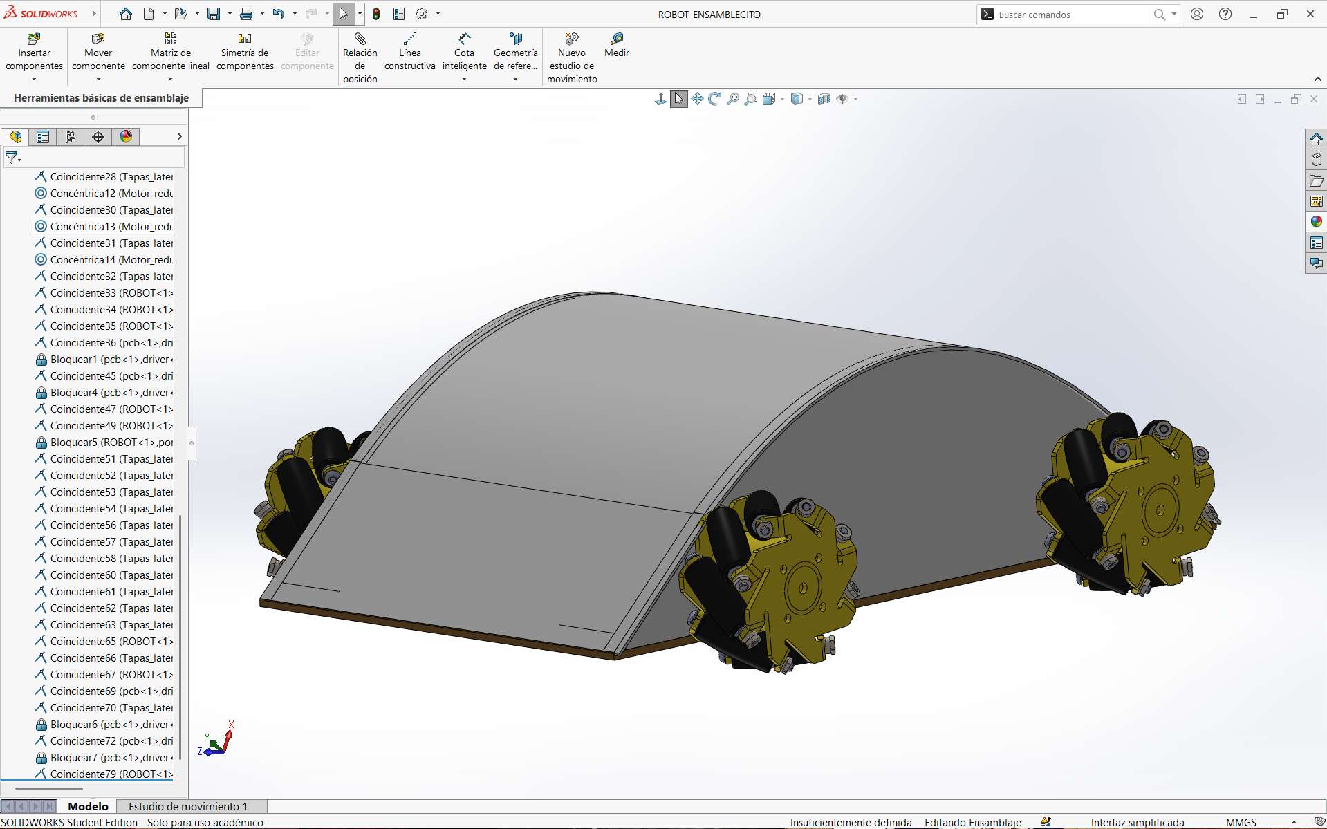
And you can observe the representative model of system integration. Where the cables represent the connections that will be made inside the car.
Conclusions
System integration is an essential part of the final project because it allows combining electronics, programming, manufacturing, and mechanical design into one functional system. Through this process, I was able to organize the project in a more structured way and identify the necessary components for the robot to work correctly. In addition, designing the PCBs and the 3D structure helped me better understand how each subsystem interacts with the others and how every design decision directly affects the final performance of the robot.