3D PRINTING AND 3D SCANNING
Individual assignments
- Design, document and 3D print an object (small, few cm3, limited by printer time) that could not be easily made subtractively
- 3D scan an object (and optionally print it)
3D Modeling Rules
It is important that certain modeling rules are followed for 3D printing. For example, the design must be solid and should not contain gaps or holes. The size, shape of the model, design patterns, and material used must also be considered.
Likewise, it is necessary to design a piece that is resistant and easy to print. For this, aspects such as wall types, sharp edges, and the supports that will be used must be taken into account.
Why This 3D Printed Piece and Not Another Manufacturing Process?
The type of piece I selected and designed is specifically intended for manufacturing through 3D printing. Since it has movable joints, these must be precisely adjusted in terms of size, tolerances, number of segments, etc. Additionally, these pieces have a geometric complexity that is more difficult to achieve using traditional manufacturing processes than with 3D printing.
Using 3D printing for this type of piece is more convenient because it offers several advantages, such as obtaining a single functional piece without the need for post-assembly processes (completely opposite to what would be required in a traditional process such as injection molding). It also helps avoid material waste, eliminates the need for complex molds, reduces costs, and is more viable overall. Therefore, 3D printing allows the manufacturing of complex parts in a single stage, with precision and efficiency.
Recommended Aspects to Consider
Here you can find some recommended aspects to consider when designing for 3D printing:
| Recommendation | Description |
|---|---|
| Rounded corners | It is better to apply rounded corners to avoid sharp angles, as these concentrate stress or may lift during printing, causing deformation. |
| No body intersections | If a model contains multiple bodies, they should not intersect but instead be combined. Intersections may cause problems when exporting the file format. |
| Solid models | Models should not contain holes; they must be solid. If working with surfaces, a closed body must be created since surfaces have no thickness. |
| Minimum thickness | All elements must have a minimum thickness (usually 0.8 mm wall thickness). Otherwise, the material may not print correctly or lack strength. |
| Small details | Details equal to or smaller than 0.3 mm cannot be properly reproduced. |
| Spacing between bodies | If movement is required (for example, articulated parts), space must be left between connected bodies so they do not fuse together. For plastic parts, the spacing should be greater than 0.5 mm. |
| Overhangs | Additive manufacturing requires supports for upper parts, so it is recommended to avoid overhangs. |
| Part orientation | If the part is designed to withstand tensile loads, the printing platform orientation must be considered. |
| Support size | For cylindrical ribs, the minimum size is 3 mm. For rectangular ribs, the minimum size should be 2.5 × 2.5 mm. |
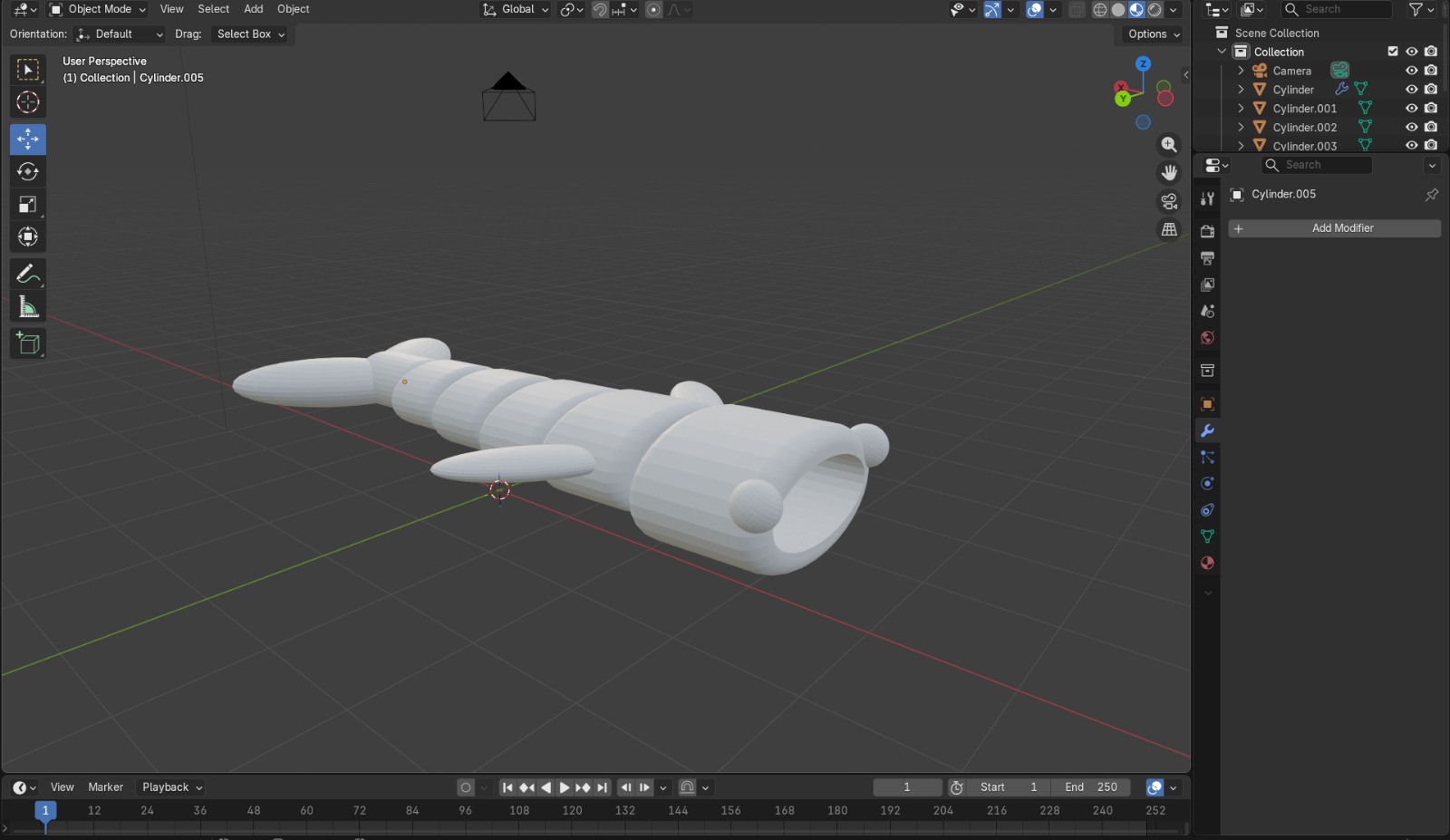
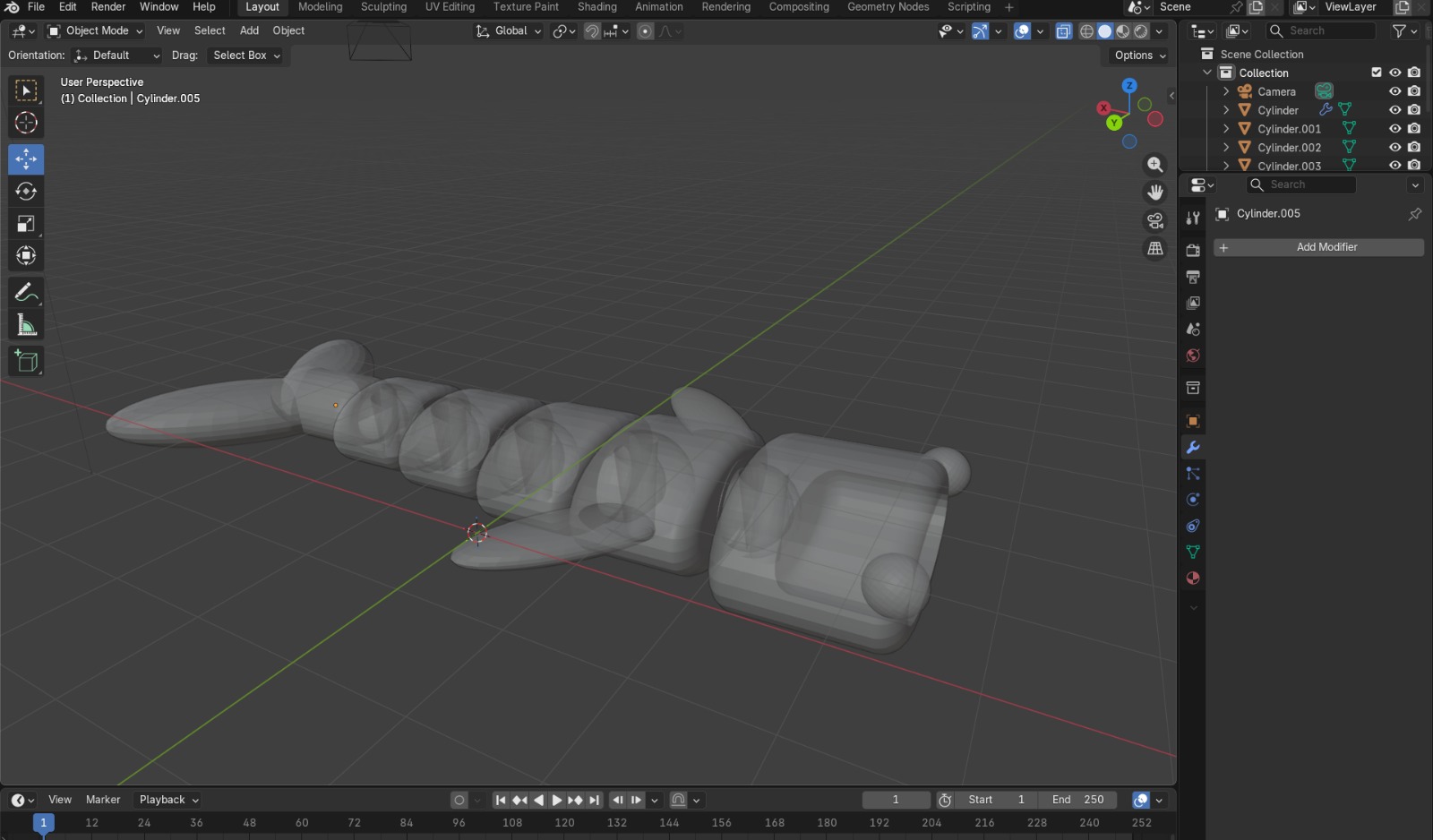
Part Design
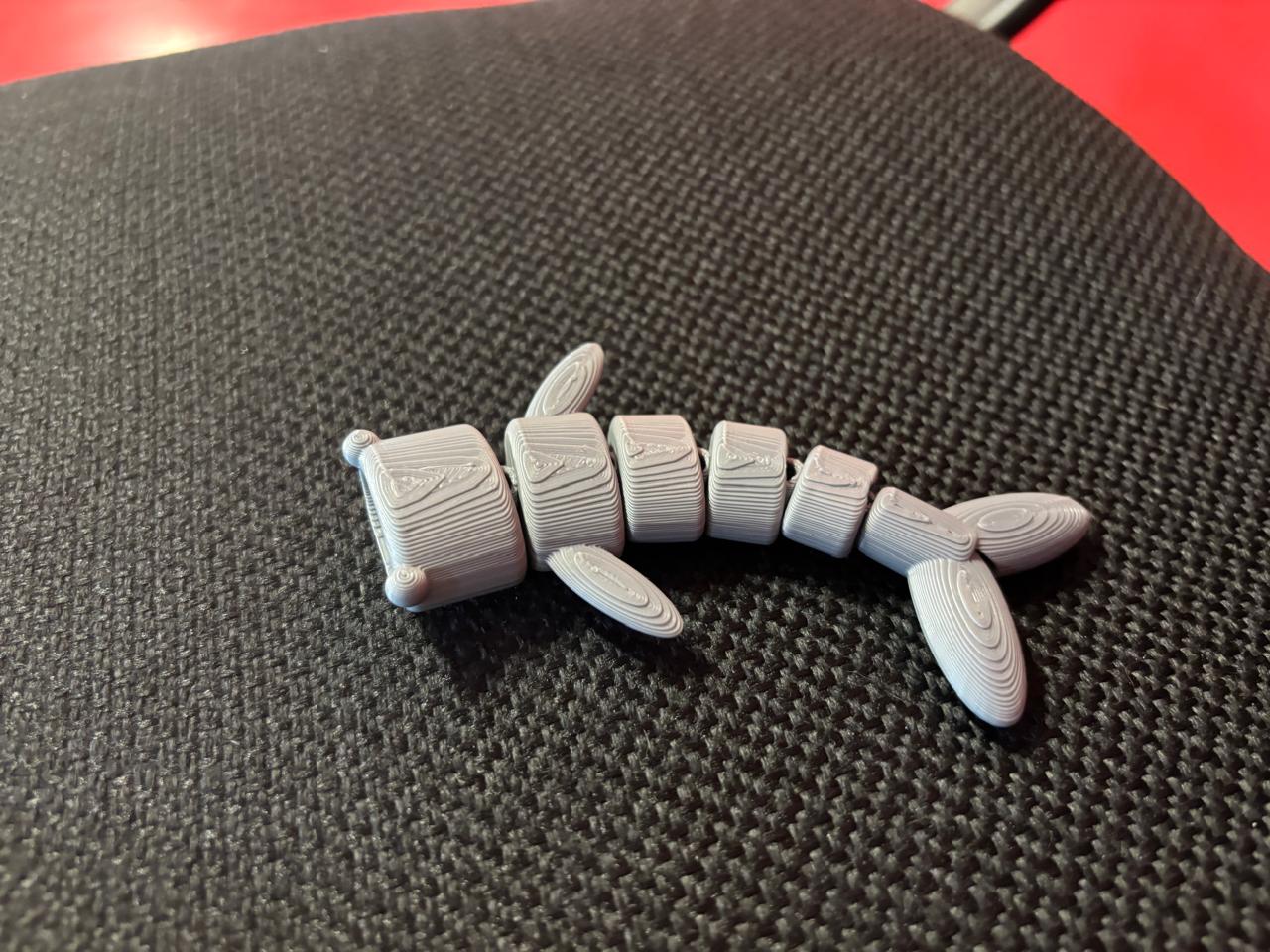
To design my piece, I was inspired by a whale. In this case, I modeled it in Blender, since this software offers various tools that facilitate the creation of parts and links for later printing. In my case, I wanted to create an articulated piece, so I added these articulated sections to the model.
What Is an Articulated Piece?
An articulated piece is one that contains interconnected segments joined by elements called joints. These joints allow movement between segments. They are widely used in robotics.
File Format
To print the piece, I had to save my file in STL format. This format allows me to export my pieces to software where I can configure 3D printer parameters. This file type describes the surface geometry of 3D objects using connected triangular meshes.
Printing Materials vs. Temperature
There are different types of materials for 3D printing, including:
| Material | Characteristics |
|---|---|
| ABS (Acrylonitrile Butadiene Styrene) | Tough, durable, and resistant to impact and heat. |
| PLA (Polylactic Acid) | Less heat-resistant, strong, brittle, and rigid. Easier to print. |
| PETG (Glycol-modified Polyethylene Terephthalate) | Moisture-resistant and compatible with printing temperatures for faster production. |
| Nylon | Strong, durable, lightweight, hard, and flexible. |
| TPU (Thermoplastic Polyurethane) | Flexible and stretchable, impact-resistant, used for vibration damping. |
| PVA (Polyvinyl Alcohol) | Water-soluble. |
3D Printing Parameters
Some factors I considered for 3D printing were configured in UltiMaker Cura, where printing parameters are specified.
| Parameter | Description | Value that I used |
|---|---|---|
| Quality | It is the resolution quality of the piece, defined by layer height. In 3D printing, printing is done layer by layer. The smaller the layer, the better the resolution obtained. Usually, the value should not exceed 80% of the nozzle diameter. In this case, if a 0.4 mm nozzle is used, the maximum would be 0.32 mm. | 0.25 |
| Walls | Refers to the walls of the piece. Layers are placed between the walls. The more walls, the greater the resistance and mechanical strength. | 4 |
| Top/Bottom | These are the layers parallel to the piece. | 2 layers |
| Infill | 0% infill is used when creating a shell, while 100% infill is for a completely solid piece. For very strong pieces, more than 50% infill can be used. For more common parameters, 10% to 20% infill is used. | 15% |
| Material | Different parameters are required. It is important to check the temperatures at which materials melt properly to define them here. For PLA, 200°C is used. The bed temperature is also changed so that the piece adheres correctly and can later be removed properly. | Material: 200°C / Bed: 60°C |
| Speed | It is the speed at which the piece is printed. It is important to consider this parameter, since higher speeds increase the possibility of printing errors.Recommendation: 60–100 mm/s. | Print speed: 60 mm/s |
| Supports |
There are two types of supports:
Placement:
|
Depends on the piece |
| Build Plate Adhesion |
Prevents the piece from detaching. Types include:
|
Brim |
3D printing process
To perform my 3D print, I first created my pieces and then exported them in STL format. The main software used to configure printers includes (click if you want to access to the website to download):
In my case, I prefer UltiMaker Cura because its interface is simpler and more intuitive. No login is required. The steps I followed were:
- Define the printer that will be used. In my case, at my university we have the Creality Ender-3 S1 Pro. Subsequently, we can access the general interface.
- Subsequently, I dragged my part file and adjusted the corresponding printing parameters.
- Once the parameters were adjusted, we pressed Slice, and this allowed the changes to be applied to the part.
- If you want to visualize the preview, select the indicated tab, and with the bar located on the right, you will be able to see the layer-by-layer construction that will be carried out.
- At the bottom, the time it will take to print the piece can be observed. Finally, name and save this file in G-code so that the printer can read it.
- Because the printer I used works through an SD memory, I had to use a memory adapter in order to save it correctly.
- Once this step was completed, I inserted the SD memory back into the printer, searched for my file name on the screen, selected it, and pressed print. This allows the printer to perform the programmed tasks.
- It is recommended to constantly supervise the piece to observe if there is any printing error and correct it.
- Once finished, remove the piece and eliminate the support created.
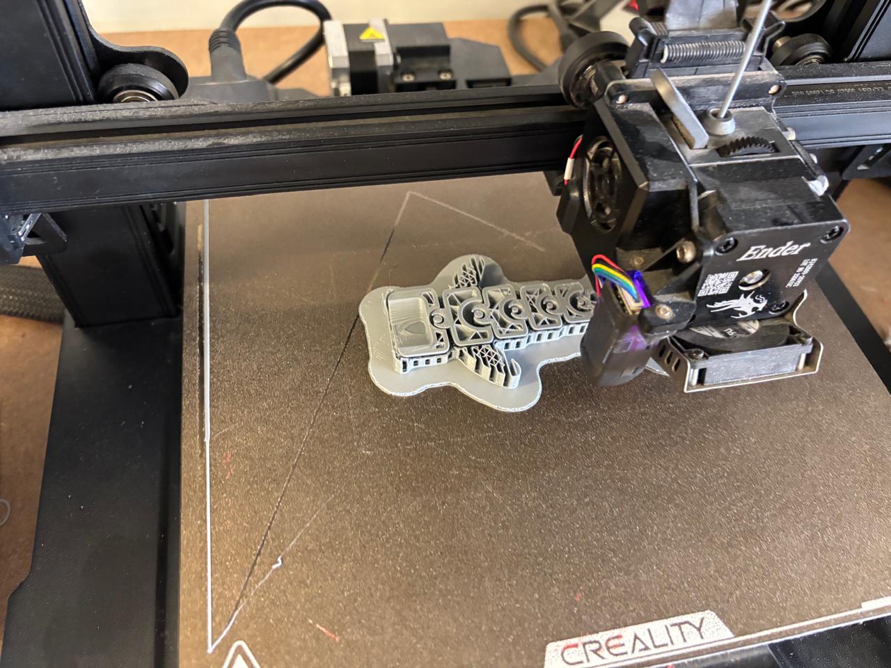
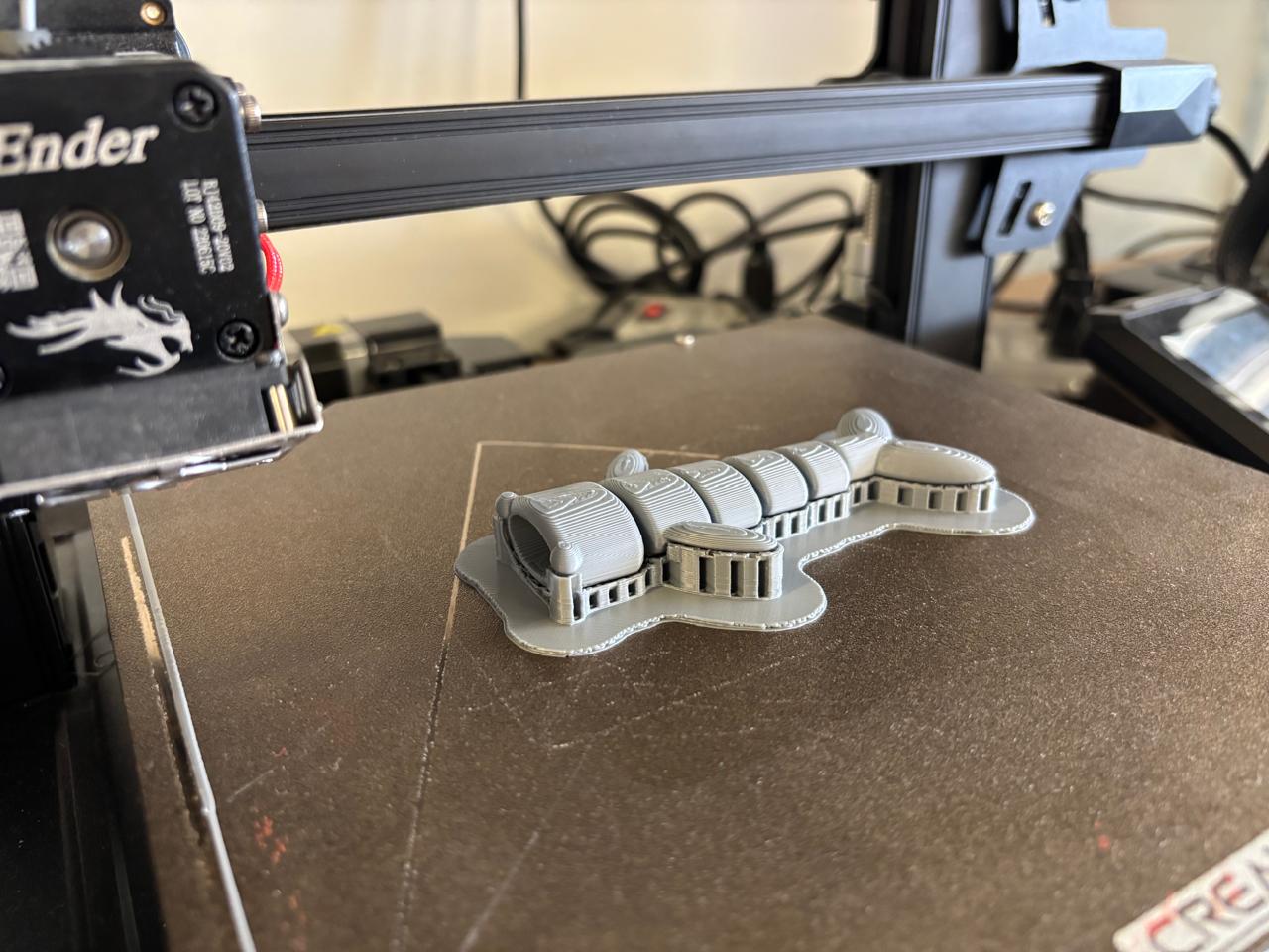
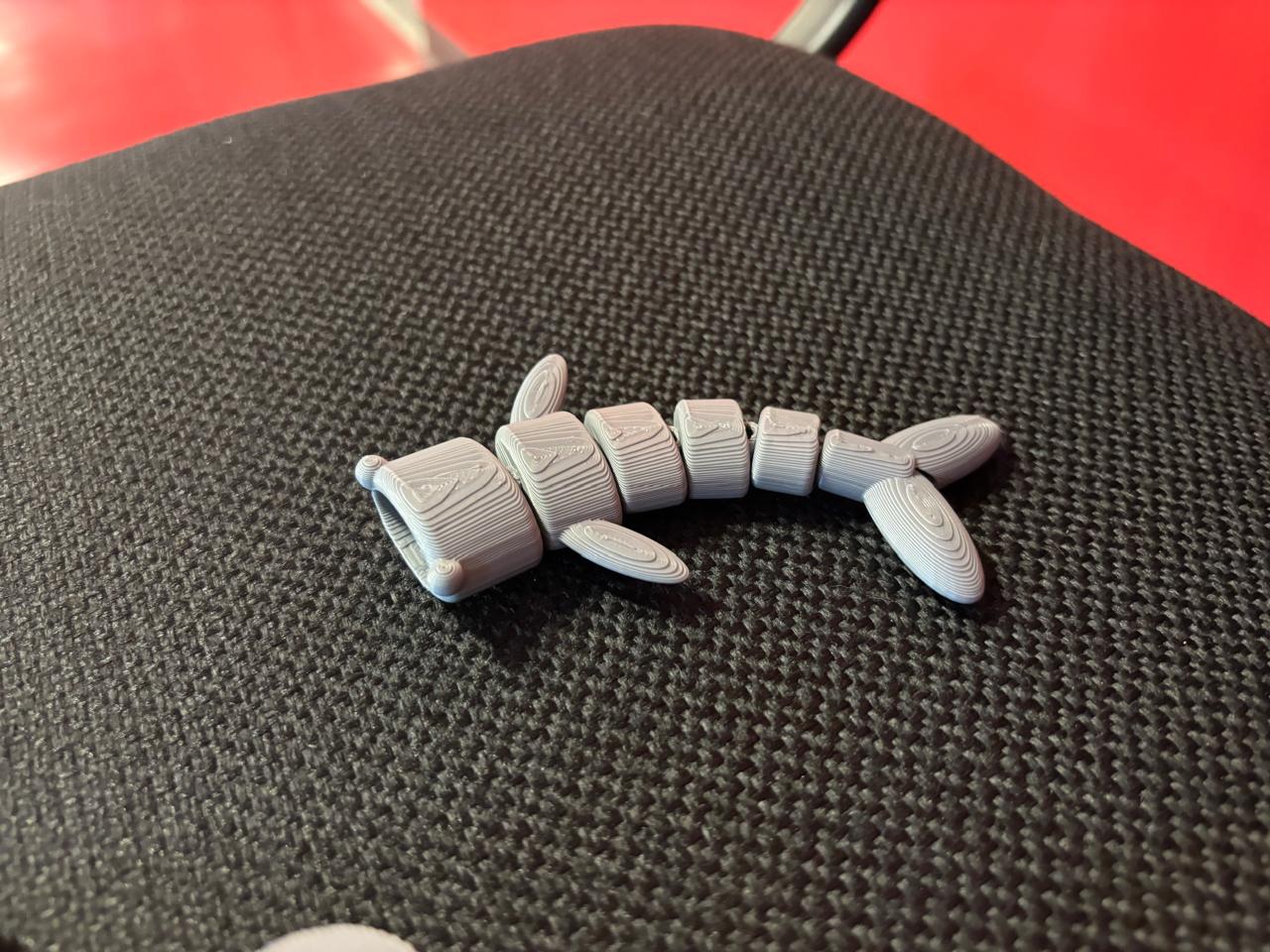
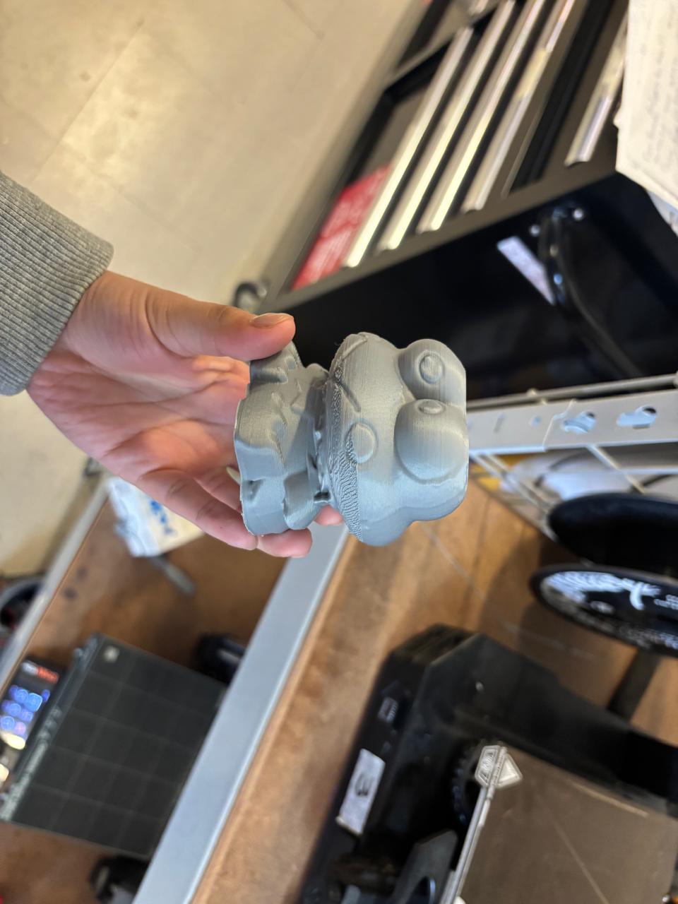
Printing Results
Finally, from my modeled pieces, I obtained the following results:
And this is how it looks like:
3D SCANNING
3D scanning is the collection of data from real objects or environments. It allows capturing shape, geometry, and even color to convert them into digital 3D models. This technology is widely used in engineering, 3D printing, medicine, etc.
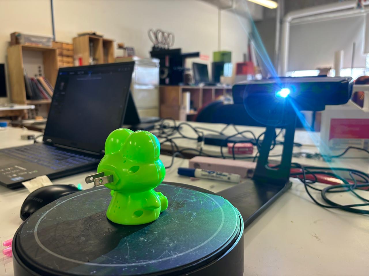
The scanner consists of a camera and a rotating base. To operate it, I used the EinScan program. This scanner works by illuminating an object and capturing the reflected light through mirrors and lenses. The captured data is converted into digital files (pixels).
Process of scanning
The steps I followed for scanning were the following:
- Connect the scanner to the computer and download the EinScan program
- Open the EinScan program and log in. Then, the scanner will be detected. From this point, it is necessary to first perform camera calibration. This consists of three tests in which you must place the grid with the pattern in front of the camera, avoiding the red box touching the circles. Preferably, these should be avoided from appearing red, as this indicates too much light; however, calibration can continue even if they appear red. This first test must be done in three steps, in which the scanner will emit light and rotate the base until it finishes.
- Once this is done, continue with the white balance test, where a sheet of paper is placed over the pattern so the camera calibrates and colors can be reproduced naturally.
-
Once calibration is complete, place your object on the base and modify the parameters according to what you want to obtain. In my case, I used the following:
Parameter What is it for? Value I used Brightness Controls the brightness of the captured image Low intensity Turntable Steps Controls the number of steps the turntable rotates during scanning 13 Turnatable Speed Controls the speed of the turntable during scanning 4 Note: If your object is very shiny like mine, you can apply some type of powder, such as makeup, to reduce the shine, since this can affect scanning. Likewise, very dark objects are not detected very well by the camera, since they absorb all the light.
- Once this is done, begin the scanning process. You can perform as many scans as necessary so that your piece is as well-defined as possible.
- Once scanning is finished, you have the option to mesh the design. This allows the surfaces of the piece to be smoothed, giving it a more uniform appearance.
- Finally, you can save your file in the desired format. In my case, STL for 3D printing.
Results of 3D Scanning
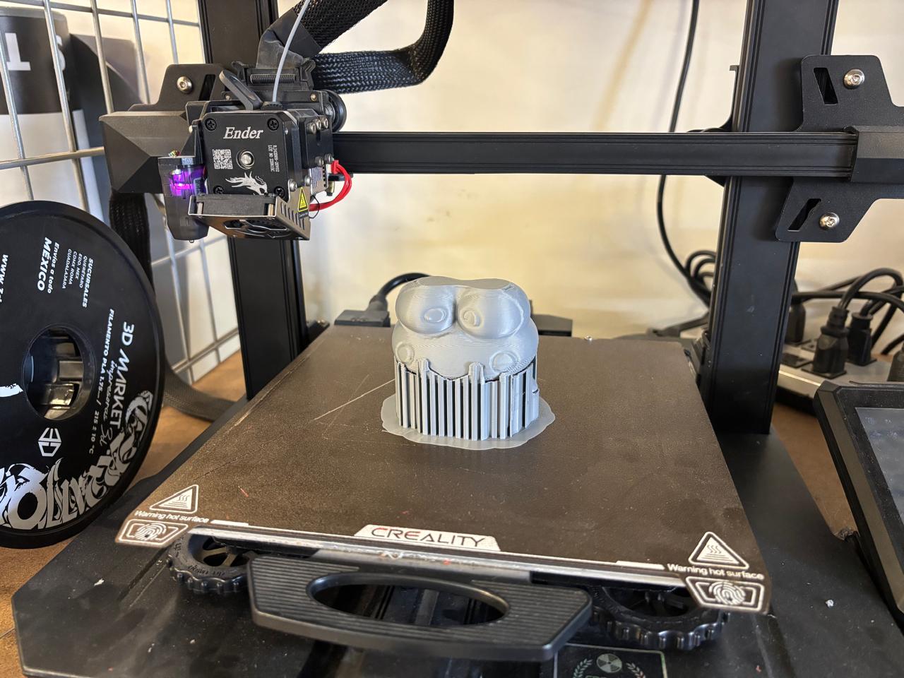
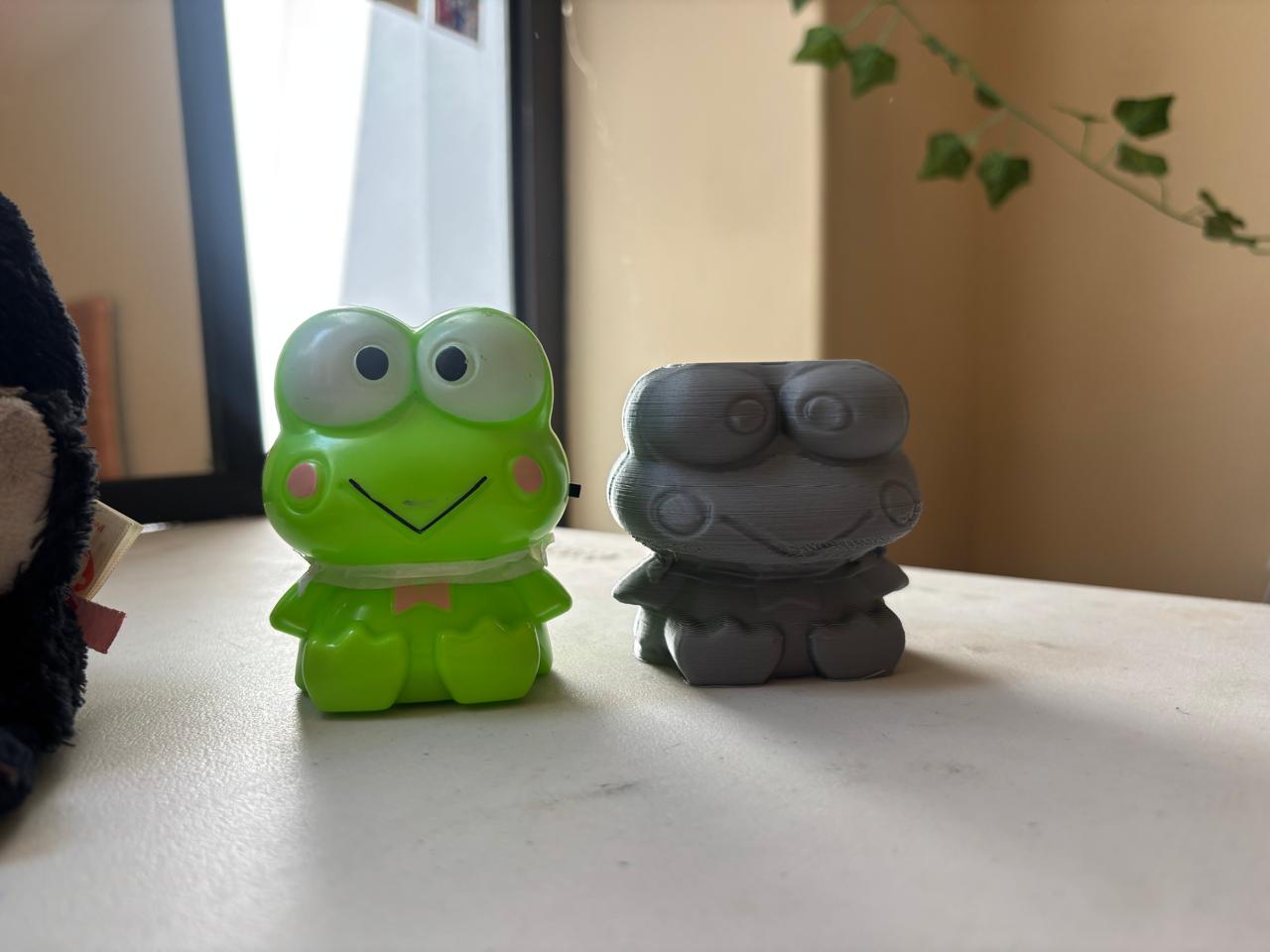
This was the final file of my scanned piece.
To print the piece, I again used UltiMaker Cura, scaled the file, and this is how my piece turned out.
Conclusions
Without a doubt, it is good practice to learn how to scan and print in 3D. This is a tool that can be widely used in different applications (depending on what you want to achieve). Likewise, it is necessary to understand the operation of each of the tools we use, since there are rules and parameters that must be followed to obtain the expected results, with quality and strength.
If you want to access to my work from this week, please click here to download!
Finally, for the group assignment for this week, you can find the information here