Embedded Programming
Individual assignment
- Browse through the data sheet for a microcontroller.
- Write and test a program for an embedded system using a microcontroller to interact (with input &/or output devices) and communicate (with wired or wireless connections).
- Extra credit: assemble the system.
- Extra credit: try different languages &/or development environments.
What is a Microcontroller?
A microcontroller is a small computer integrated into a single chip. It is designed to perform specific tasks within an embedded system. These compact integrated circuits contain a processor core, random-access memory (RAM), and programmable read-only memory (ROM), which can be erased and rewritten to store programs.
Components of a Microcontroller
- Central Processing Unit (CPU): It is the brain of the microcontroller and is responsible for executing instructions and controlling operations.
- Memory: Microcontrollers include memory units that store temporary data required during operation.
- Peripherals: Depending on the application, microcontrollers may include various auxiliary components such as input/output (I/O) interfaces, timers, counters, analog-to-digital converters (ADC), and digital-to-analog converters (DAC).
Different Sizes of Microcontroller Boards
8-bit Microcontrollers
These are basic microcontrollers commonly used in simple devices such as remote controls. They are suitable for small and simple tasks.
16-bit Microcontrollers
These are more powerful than 8-bit microcontrollers and are commonly used in tools, printers, and similar devices.
32-bit Microcontrollers
These are more advanced, faster, and more powerful chips. They are commonly used in smart devices.
64-bit Microcontrollers
They are capable of handling very large amounts of data and are mainly used to perform multiple tasks simultaneously.
What is a Pin?
1. A pin is a metallic terminal of the microcontroller. Pins can receive information, send information, provide power, or act as ground (0 V). Digital pins (D0–D13) can only read or output LOW (0 V) or HIGH (5 V) signals. These pins are commonly used to turn LEDs on or off, read buttons, and perform similar tasks. Usually, resistors are required to protect the components.
2. Analog pins (A0–A5) are used to measure variable values, such as those coming from potentiometers, light sensors, or temperature sensors.
3. On the other hand, GND represents ground and acts as a voltage reference. All components connected to the microcontroller must share the same GND.
Also, the following aspects must be considered:
- Every circuit requires a GND connection.
- All components must share the same GND.
Microcontroller technical specifications
ESP32 Microcontroller
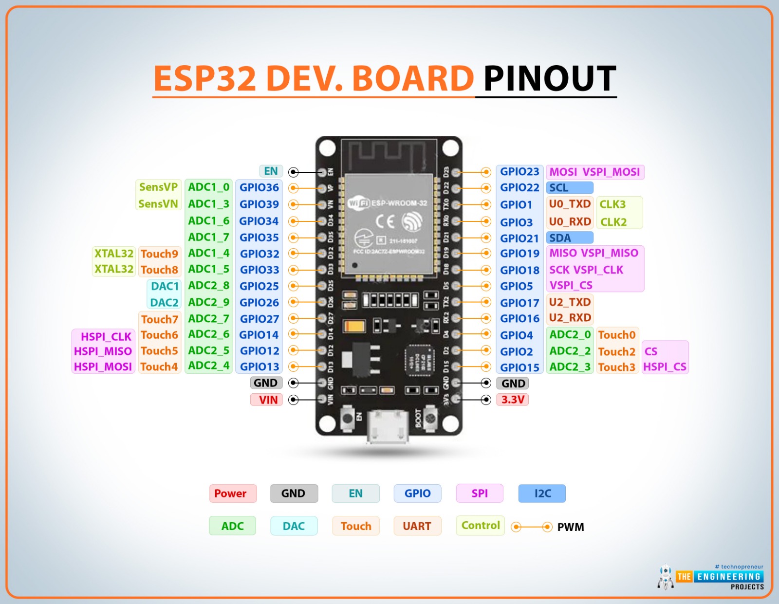
The datasheet can be found here
| Features | ESP32 |
| CPU | Xtensa single-/dual-core 32-bit LX6 microprocessor(s) |
| Clock Speed | Up to 240 MHz |
| Bit Depth | CPU: 32 bits, ADC (analog): 12 bits |
| Storage | 448 KB ROM, 520 KB SRAM, 16 KB SRAM in RTC |
| I/O pins | 34 programmable GPIOs |
| Power | 3.3 V |
| Dimensions | 5 × 5 mm |
| Bluetooth | Compliant with Bluetooth v4.2 BR/EDR and Bluetooth LE specifications, Class-1, class-2 and class-3 transmitter without external power amplifier, Enhanced Power Control, +9 dBm transmitting power |
| Wifi | 802.11n (2.4 GHz), up to 150 Mbps |
| How to program | Arduino IDE, ESP-IDF, MicroPython, C/C++ |
| Special Functions | Touch Sensor, ULP coprocessor, PWM. |
Raspberry Pi Pico Microcontroller
The datasheet can be found here
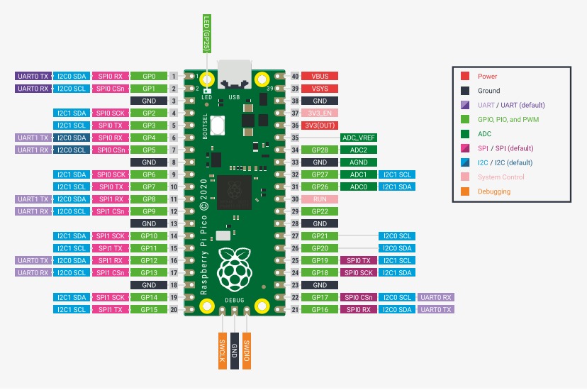
| Features | RP2040 |
| CPU | Microcontrolador: RP2040, ARM Cortex-M0+, Dual-core, Bits: 32 bits |
| Clock Speed | Up to 133 MHz |
| Bit Depth | 32-bit, ADC: 12 bits (0–4095) |
| Storage | 264KB of SRAM, and 2MB of on-board Flash memory |
| I/O pins | 26 GPIO |
| Power | 3.3 V |
| Dimensions | 51 × 21 mm |
| Bluetooth | No |
| Wifi | No |
| How to program | C / C++, MicroPython, Arduino IDE |
| Special Functions | USB 1.1 Host/Device, 8 Programmable I/O (PIO) state machines |
Arduino Microcontroller
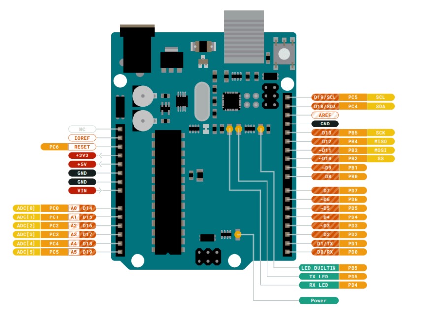
The datasheet can be found here
| Features | ATmega328P |
| CPU | AVR RISC, 8 bits |
| Clock Speed | Up to 16 MHz |
| Bit Depth | CPU: 8 bits, ADC: 10 bits (0–1023) |
| Storage | Flash: 32 KB, SRAM: 2 KB, EEPROM: 1 KB |
| I/O pins | 14 digital pins (D0–D13), 6 analog pins (A0–A5), 6 PWM pins |
| Power | Operating voltage: 5V, VIN input: 6–20V, USB: 5V |
| Dimensions | 68.6x53.4 mm |
| Bluetooth | No |
| Wifi | No |
| How to program | Arduino IDE (Desktop), Arduino Cloud Editor, Lenguaje: C / C++ (Arduino) |
| Special Functions | Timers (8-bit and 16-bit), PWM (6 channels), UART, SPI, I2C, Watchdog Timer, Per Pin Interrupts. |
Embedded System Simulation
I chose ESP32-WROOM microcontroller because I consider its characteristics and components suitable for my project since it can be connected to Bluetooth and Wi-Fi, and these options can help me to develop my project in the future. An Esp32 is also an available microcontroller that is simple to use and program. Additionally, it includes multiple functions that allow me to control a more complex system, especially for managing the mobility of the vehicle. It allows me to do multiple tasks at the same time, as reding sensors, control motors, using wireless communications, low energy consumption, wide variety of modules. I did this simulation in Wokwi as it's a great free tool that can be fully utilized.
Initially, I learned how to turn on LED lights through programming. Later, I gradually added more components. Finally, I created a simulation using an ultrasonic sensor, as this sensor allows me to better understand the elements I will work with throughout my project.
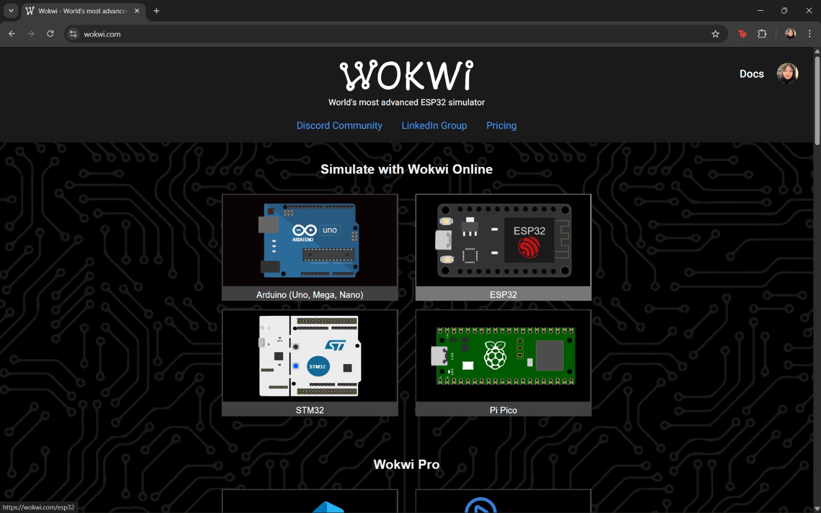
How to use Wokwi?
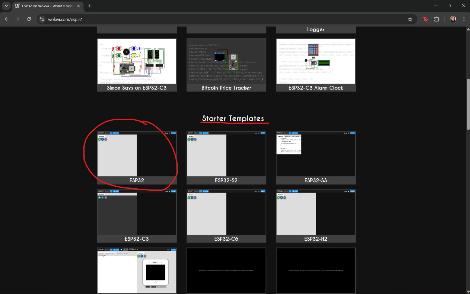
- Access Wokwi
- Once the previous step is completed, a window like the following will appear. In this interface, different types of microcontrollers that can be used or tested are displayed.
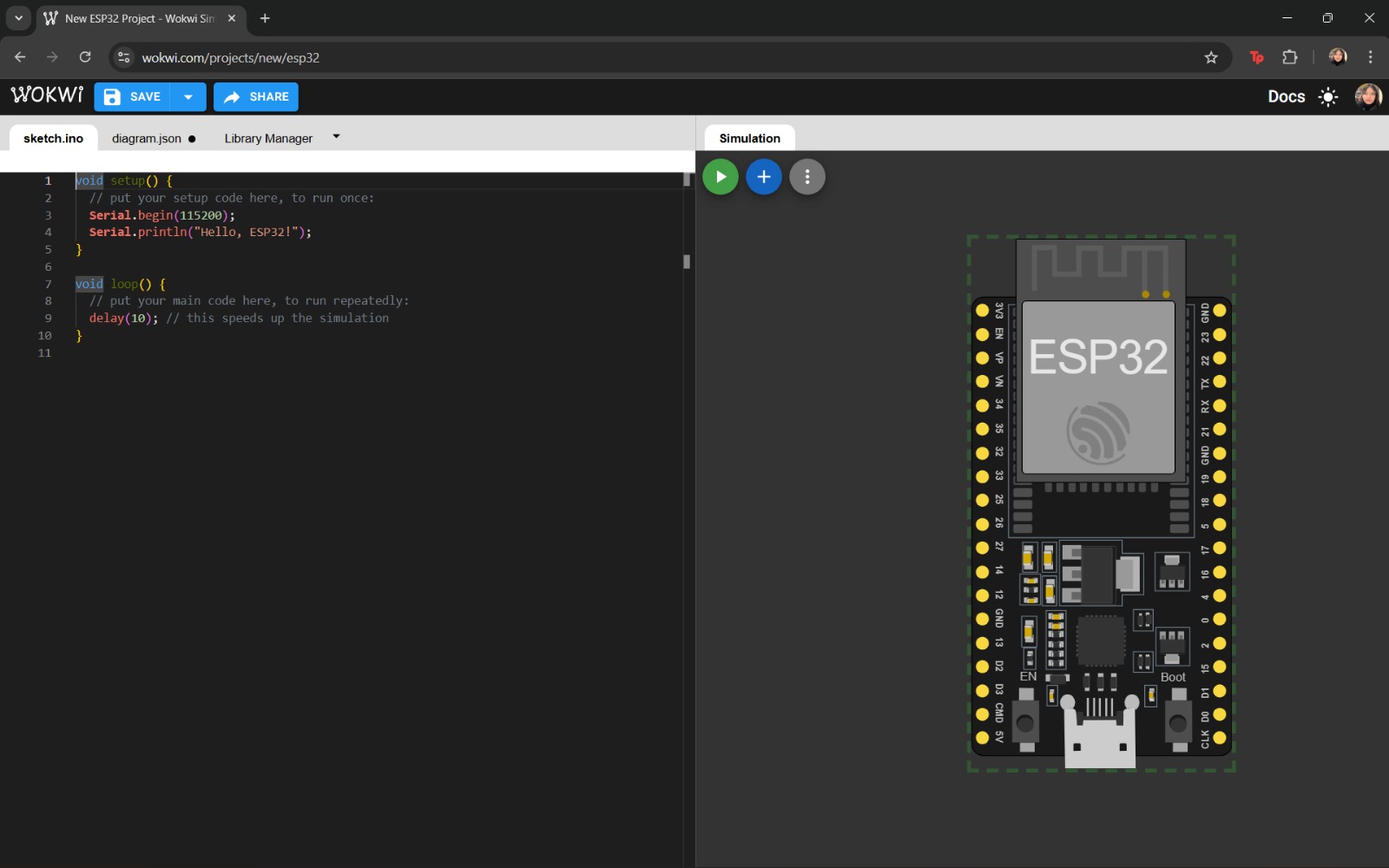
- After selecting the desired microcontroller, a new window will open showing the program code and a preview of the simulation. Additional components can be added by selecting the “+” option.
- Once the system has been assembled, press the Play button to run the simulation.
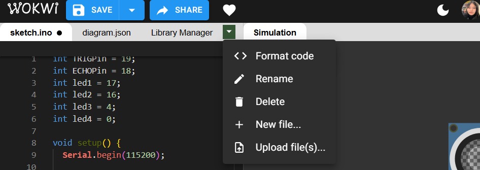
- If you wish to perform additional operations to modify the current file, select the tab located next to “Simulation.” From this menu, you can modify the code format, rename files, delete them, or create and add a new document.
Note: Do not forget to save your changes.
C++ Code Structure for Arduino IDE
For me, it was very important to understand the structure to follow when programming. I used the following structure:
- Global constants and variables: Pins, states, speeds, and sensors used in the program can be defined here. It is important to place them at the top of the code because they are used throughout the entire program.
setup(): This function refers to the initial configuration. It runs only once and defines which pins are used, whether they are inputs or outputs, and whether they are used for communication.loop():This function defines the behavior of the program. It specifies what happens first, next, and the waiting times. Functions can be called here to repeat specific behaviors.
This structure allows the program to be configured, executed, and divided into tasks. Additionally, there are fundamental programming structures that should be considered or learned:
IF/ELSE> Conditional statements used to make decisions. The if statement executes when a condition is met, while else executes when the condition is not met.WHILE: This function allows commands to repeat continuously while a condition remains true.FOR: A controlled repetition structure that repeats a block of code a specific number of times.
Programming Language
The programming language used in this project is C++. Some of the most important commands include:
Pin Commands
pinMode(pin, mode)
This command configures a pin on the microcontroller. The modes include OUTPUT (sends information), INPUT (receives information), and INPUT_PULLUP (configures a digital pin as input and activates the internal resistor).
It is used at the beginning of the program or inside setup() to define the behavior of the pin.
digitalWrite(pin, value)
This command sends electricity to the pin. The values can be HIGH, which sends full voltage, or LOW, which sends no voltage.
It is used inside loop() to change the state of a physical component.
digitalRead(pin)
This command reads a digital pin as either 0 (0 volts or GND) or 1 (high voltage of 3.3 V or 5 V). It is used to read signals and is only applied when a yes/no condition is required.
Time Commands
delay(ms)
Pauses the program for a specified number of milliseconds.
millis()
Returns the time elapsed since the microcontroller was powered on. It is commonly used for timers, smooth movements, and to avoid blocking delays.
Analog Commands
analogRead(pin);
In the case of the ESP32 microcontroller, it reads values from 0 to 4096. It helps determine changes in signals and gradual variations.
analogWrite(pin, value)
Allows speed control using PWM (Pulse Width Modulation).
Serial Communication Commands
Serial.begin()
Starts serial communication and is placed inside setup().
Serial.print
Displays data through the serial monitor and is placed inside loop().
It is important to consider the main operators, which are:
| Operator | Meaning |
| == | Equal |
| != | Not equal |
| < | Less tan |
| > | Greater than |
| && | AND |
To declare blocks of code using functions, the data type is specified first, followed by the function name. Example:
            int leerSensor() {
                return 123;
            }
The existing data types include:
void:returns no dataint:returns an integerbool:returns true or falsefloat:returns a decimal value
A useful example that helped me understand and become familiar with programming structure follows this format:
()contains the required parameters.{}contains the instructions executed by the function.
LED simulation with buttons
First, I created a simulation using a button and an LED.
This was the result:
Subsequently, I increased the number of LEDs and buttons.
So, here you can find this simulation.
The code used was written in C++ and programmed following the structure described above. In this code, the first section declares the pins that will be used, followed by the definition of their corresponding input types. Finally, the code allows a series of actions to be executed continuously, in which the signals from the buttons are read and, based on these inputs, a decision is made regarding which LED will turn on.
This code is an excellent example for beginning to become familiar with programming this type of system, understanding its structure, and experimenting with simulations in a safe and interactive manner.
                int led1 = 23;
                int led2 = 22;

                int boton1 = 18;
                int boton2 = 19;

                void setup() {
                  pinMode(led1, OUTPUT);
                  pinMode(led2, OUTPUT);
                  pinMode(boton1, INPUT_PULLUP);
                  pinMode(boton2, INPUT_PULLUP);
                }

                void loop() {
                  int estadoBoton1 = digitalRead(boton1);
                  if (estadoBoton1 == LOW) {
                    digitalWrite(led1, HIGH);
                  }
                  else {
                    digitalWrite(led1, LOW);
                  }

                  int estadoBoton2 = digitalRead(boton2);
                  if (estadoBoton2 == LOW) {
                    digitalWrite(led2, HIGH);
                  }
                  else {
                    digitalWrite(led2, LOW);
                  }
                }
Simulation with ultrasonic sensor that turns on LEDs
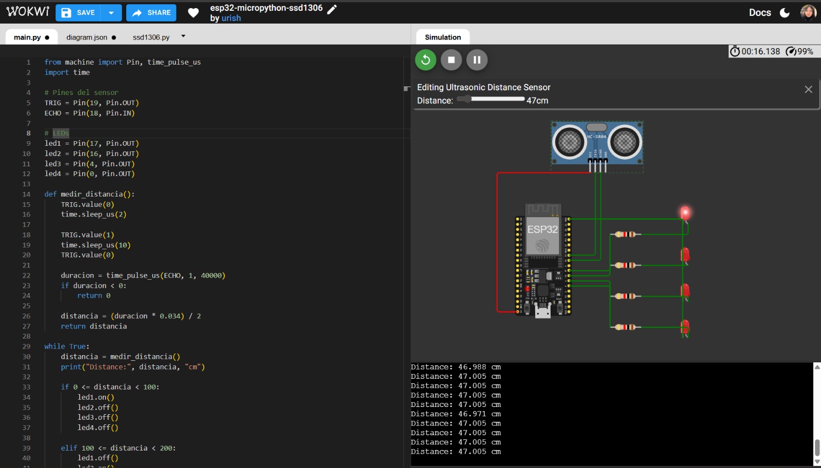
For the second example, I used an ultrasonic sensor in order to become familiar with its operation.
Later, additional LEDs were added.
In this simulation, it was planned that, based on the data obtained from the ultrasonic sensor, the distance between objects could be calculated and, from this information, determine which LED would be activated. This code implements a more advanced use of programming, as it includes different instructions that allow signals to be sent and received, which is essential due to the sensor being used. Additionally, conditional statements are declared, allowing for better control over the behavior and logic integrated into this simulation. The code used was written in C++ and programmed following the structure described above.
                int TRIGPin = 19;
                int ECHOPin = 18;
                int led1 = 17;
                int led2 = 16;
                int led3 = 4;
                int led4 = 0;

                void setup() {
                  Serial.begin(115200);

                  pinMode(TRIGPin, OUTPUT);
                  pinMode(ECHOPin, INPUT);

                  pinMode(led1, OUTPUT);
                  pinMode(led2, OUTPUT);
                  pinMode(led3, OUTPUT);
                  pinMode(led4, OUTPUT);
                }

                void loop() {
                  long duration;        // variable declaration
                  float distance;       // variable declaration

                  // Trigger pulse (clean signal)
                  digitalWrite(TRIGPin, LOW);
                  delayMicroseconds(2); // pause before sending the pulse

                  // Send trigger pulse
                  digitalWrite(TRIGPin, HIGH);
                  delayMicroseconds(10); // pulse duration
                  digitalWrite(TRIGPin, LOW);  // stop sending pulse

                  duration = pulseIn(ECHOPin, HIGH, 40000); // read echo pulse
                  distance = duration * 0.034 / 2;          // distance calculation

                  Serial.print("Distance: ");   // screen output
                  Serial.print(distance);       // print distance value
                  Serial.println(" cm");        // units

                  if (distance >= 0 && distance < 100) {
                    digitalWrite(led1, HIGH);
                    digitalWrite(led2, LOW);
                    digitalWrite(led3, LOW);
                    digitalWrite(led4, LOW);
                  }
                  else if (distance >= 100 && distance < 200) {
                    digitalWrite(led1, LOW);
                    digitalWrite(led2, HIGH);
                    digitalWrite(led3, LOW);
                    digitalWrite(led4, LOW);
                  }
                  else if (distance >= 200 && distance < 300) {
                    digitalWrite(led1, LOW);
                    digitalWrite(led2, LOW);
                    digitalWrite(led3, HIGH);
                    digitalWrite(led4, LOW);
                  }
                  else {
                    digitalWrite(led1, LOW);
                    digitalWrite(led2, LOW);
                    digitalWrite(led3, LOW);
                    digitalWrite(led4, HIGH);
                  }

                  delay(300); // waiting time
                }
If you want to access to my simulation, you can find it here.
Other Programming Languages
In addition to C++, I experimented with Micropython. This language is known for being more intuitive and easier to understand. A comparison table between programming languages is presented below.
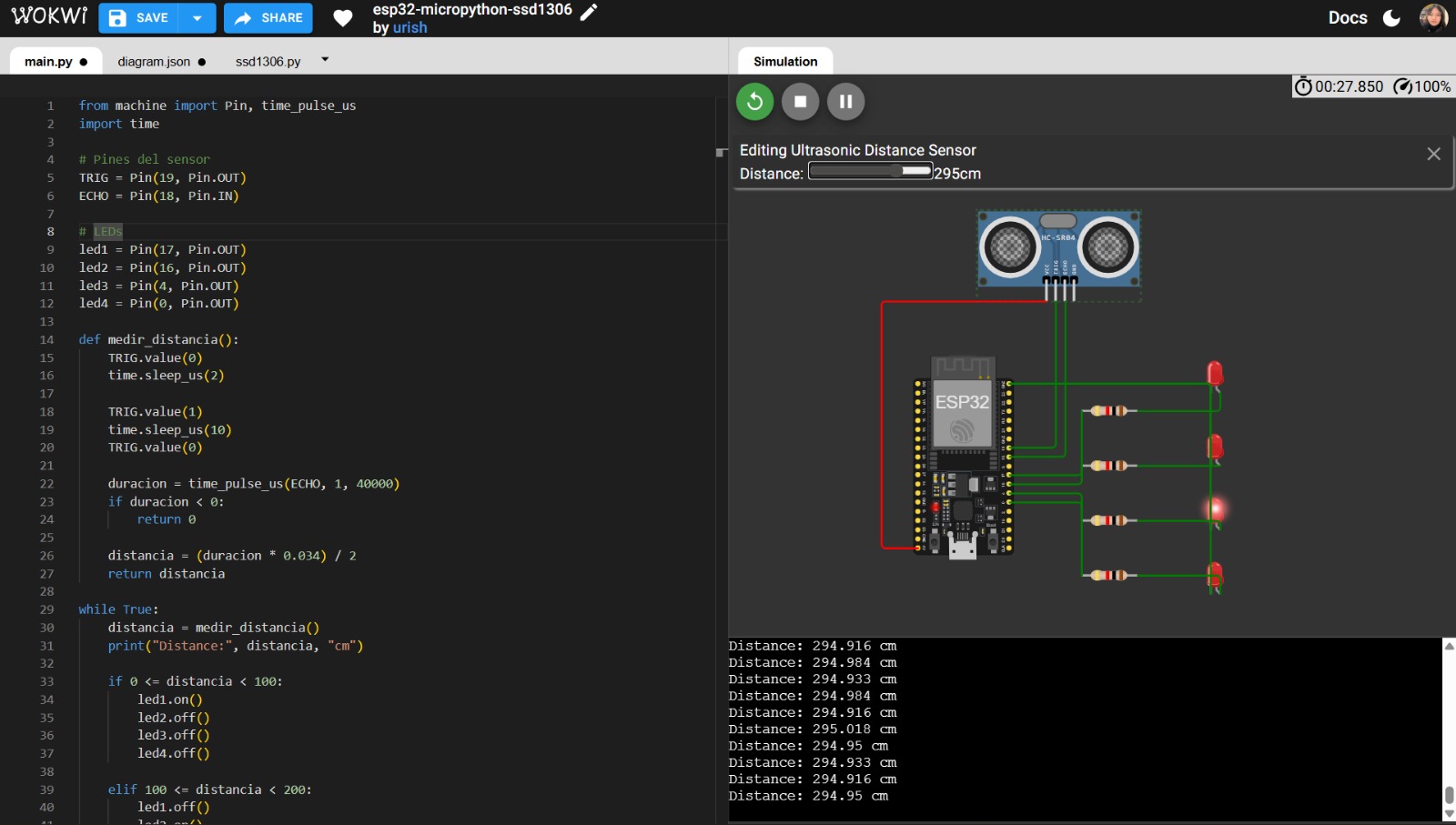
I did the same simulation to compare the programs. The code used is described above:
                from machine import Pin, time_pulse_us
                import time

                # Pines del sensor
                TRIG = Pin(19, Pin.OUT)
                ECHO = Pin(18, Pin.IN)

                # LEDs
                led1 = Pin(17, Pin.OUT)
                led2 = Pin(16, Pin.OUT)
                led3 = Pin(4, Pin.OUT)
                led4 = Pin(0, Pin.OUT)

                def medir_distancia():
                    TRIG.value(0)
                    time.sleep_us(2)

                    TRIG.value(1)
                    time.sleep_us(10)
                    TRIG.value(0)

                    duracion = time_pulse_us(ECHO, 1, 40000)
                    if duracion < 0:
                        return 0

                    distancia = (duracion * 0.034) / 2
                    return distancia

                while True:
                    distancia = medir_distancia()
                    print("Distance:", distancia, "cm")

                    if 0 <= distancia < 100:
                        led1.on()
                        led2.off()
                        led3.off()
                        led4.off()

                    elif 100 <= distancia < 200:
                        led1.off()
                        led2.on()
                        led3.off()
                        led4.off()

                    elif 200 <= distancia < 300:
                        led1.off()
                        led2.off()
                        led3.on()
                        led4.off()

                     else:
                        led1.off()
                        led2.off()
                        led3.off()
                        led4.on()

                    time.sleep(0.3)
Finally, here you can acess to my simulation.
Comparison between C++ and MicroPython Programming for ESP32
Once both programs were implemented, a comparative table is presented below, analyzing the main differences between programming in C++ (Arduino framework) and MicroPython, considering different functional categories of the system.
| Use | C++ | Micropython |
| Pin Definition | pinMode(19, OUTPUT) |
TRIG = Pin(19, Pin.OUT) |
| LED Pin Definition | pinMode(17, OUTPUT); |
led1 = Pin(17, Pin.OUT) |
| Distance Measurement Function | float medirDistancia() { |
def medir_distancia(): |
| Sending Ultrasonic Pulse |
                  digitalWrite(TRIG, HIGH);
                  delayMicroseconds(10);
                  digitalWrite(TRIG, LOW);
|
                    TRIG.value(1)
                    time.sleep_us(10)
                    TRIG.value(0)
|
| Echo Reading | duration = pulseIn(ECHOPin, HIGH, 40000); |
duracion = time_pulse_us(ECHO, 1, 40000) |
| Distance Calculation | distance = duration * 0.034 / 2; |
                distancia = (duracion * 0.034) / 2
                return distancia
|
| Main Loop | loop() |
while True: |
| Console Output |
                  Serial.print("Distance: ");
                  Serial.print(distance);
                  Serial.println(" cm");
|
print("Distance:", distancia, "cm") |
| LED Conditions |
                  if (distance >= 0 && distance < 100) {
                  digitalWrite(led1, HIGH);
                  digitalWrite(led2, LOW);
                  digitalWrite(led3, LOW);
                  digitalWrite(led4, LOW);
|
                  if 0 <= distancia < 100:
                  led1.on()
                  led2.off()
                  led3.off()
                  led4.off()
|
| Final Delay | delay(300); |
time.sleep(0.3) |
As can be observed in the comparative table, using MicroPython is easier and more intuitive to learn; however, it has slower performance and higher memory consumption. Meanwhile, C++, despite having greater learning complexity, has better performance and speed.
Conclusions
It is important to learn how to correctly use each microcontroller and understand its functions for proper application. Additionally, there are various programming languages that can be used to control microcontrollers. It is not possible to determine which language is better, as this depends on the user’s experience.
However, some languages are simpler and more intuitive, such as Python, making the choice largely personal. Furthermore, it is highly relevant to begin working with simulations using software tools that provide a complete experience combining theory and practice. Therefore, the use of these tools is convenient for safe and effective learning.
If you want to access to my work from this week, please click here to download!
Finally, for the group assignment for this week, you can find the information here