Computer Aided Design
Task
- Modelled experimental objects/part of a posible final Project in 2D and 3D softwares
- Show how did it with words/images/screenshots
- Documented how you compressed your image and video files
- Included your original design files
Main Information
What is CAD?!
CAD (Computer-Aided Design) refers to the use of computer software to create 2D drawings and 3D models. These tools allow designers to simulate, modify, and develop designs before manufacturing. CAD drawings are digital representations of objects created through technical plans, offering higher precision and detail compared to traditional hand-drawn technical drawings.
Software List
- On Shape
- Blender
- SolidWorks
- Inkscape
- Affinity Designer
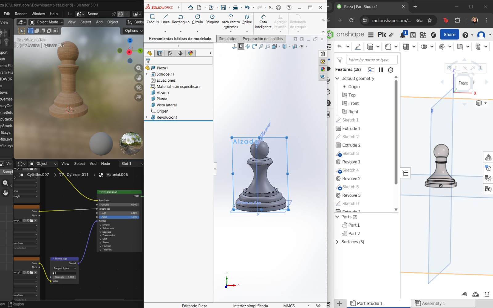
The following software tools were used and learned during this week. This experience was highly enriching. To compare the 3D modeling software, I decided to design the same chess piece (a pawn) in all three programs. For 2D graphic software, I used different reference images to explore and test their available tools.
Softwares en 2D
What are vector images?
Vector images are created using vectors or geometric objects defined by mathematical equations. This means the image is not made of pixels but of scalable paths, allowing images to be resized without losing quality. Vector images are ideal for logos, illustrations, and technical drawings.
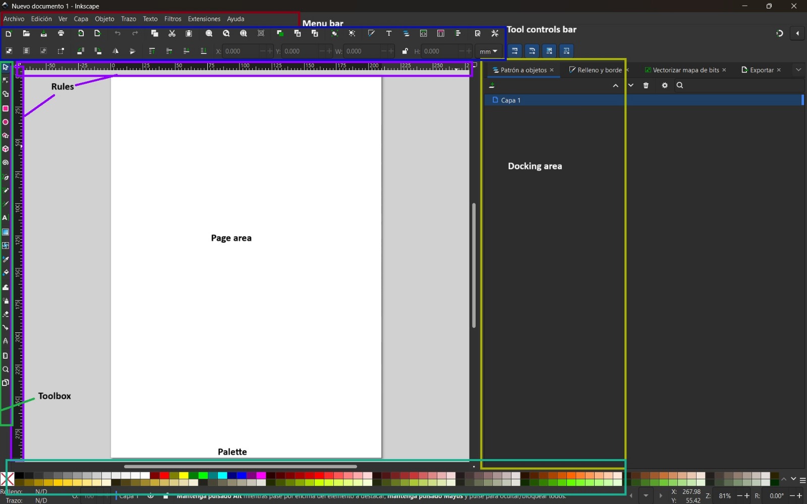
Inkscape
Inkscape is a free and open-source vector graphics editor that uses the Scalable Vector Graphics (SVG) file format. It has a simple and intuitive interface with a wide range of tools that allow highly precise drawings.
Basic Commands
- Shift + Alt + B: Trace bitmap
- Ctrl + Shift + E: Export files
- T: Text tool
- P: Pen tool
- Shift + F6: Pen tool
- Ctrl + Shift + M: Transform dialog
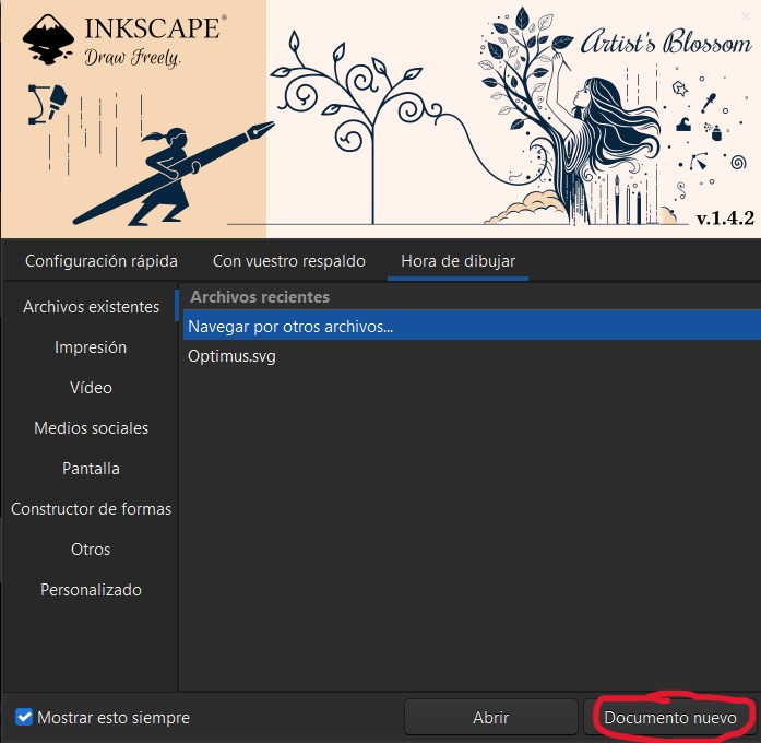
How to use Inkscape – Step by Step
- Open the program and select New Document.
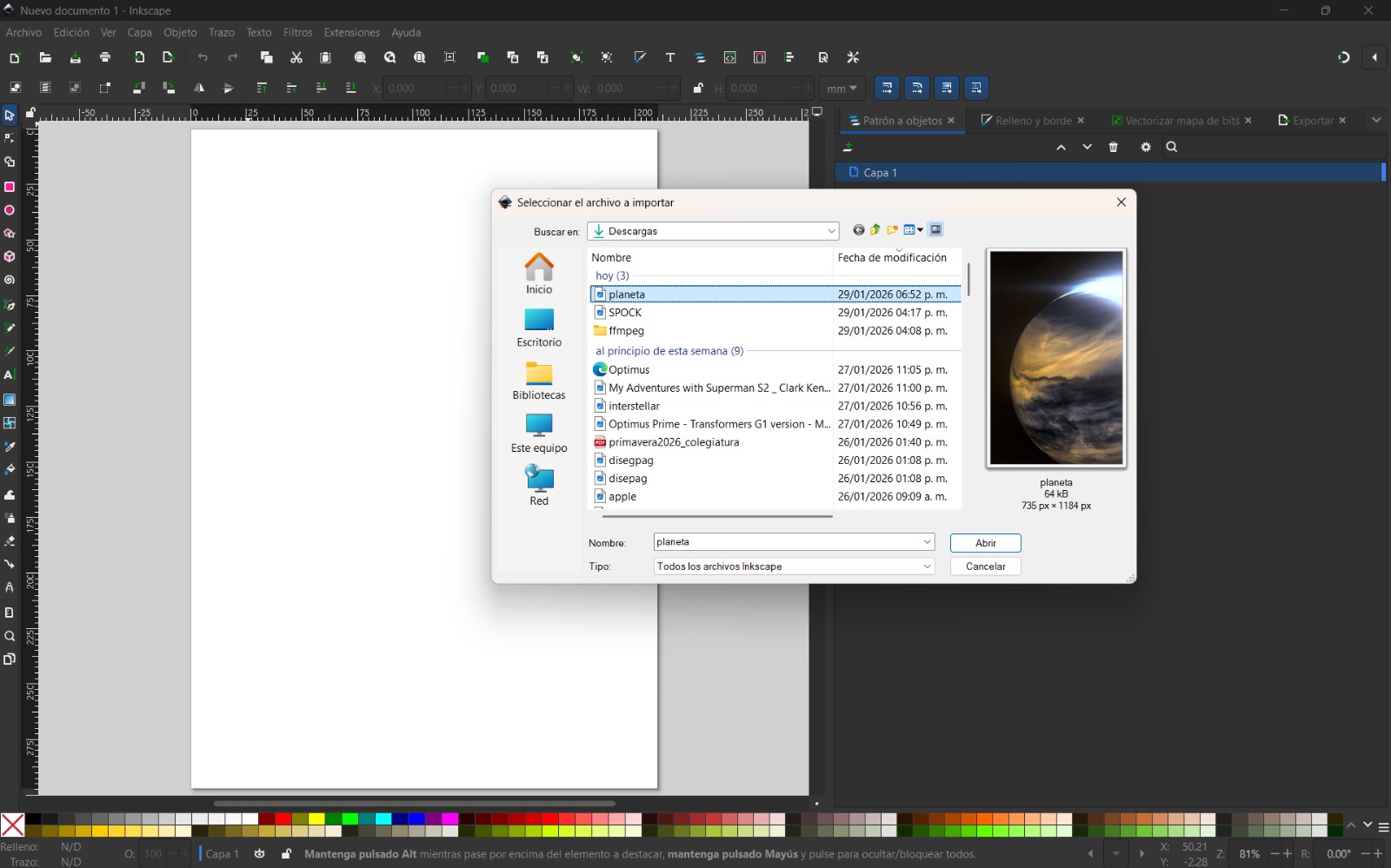
- In my case, I used an image and converted it from pixels to vectors. To do this, I selected File → Import and chose Embed image so it remained within the file.
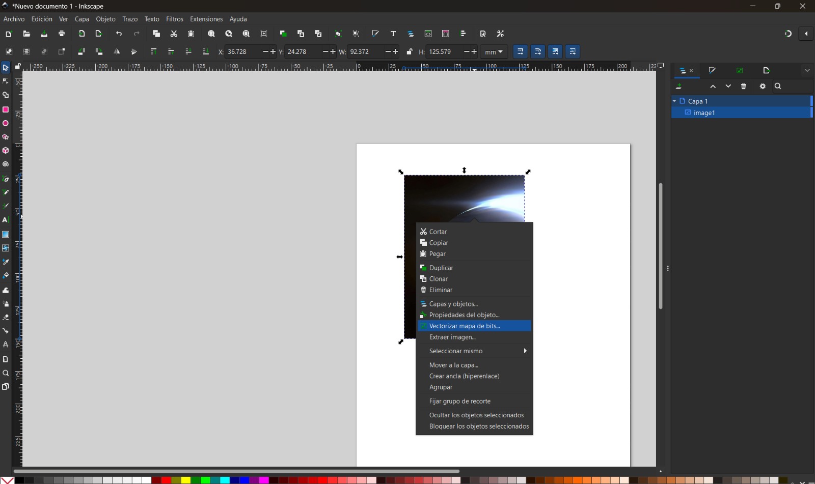
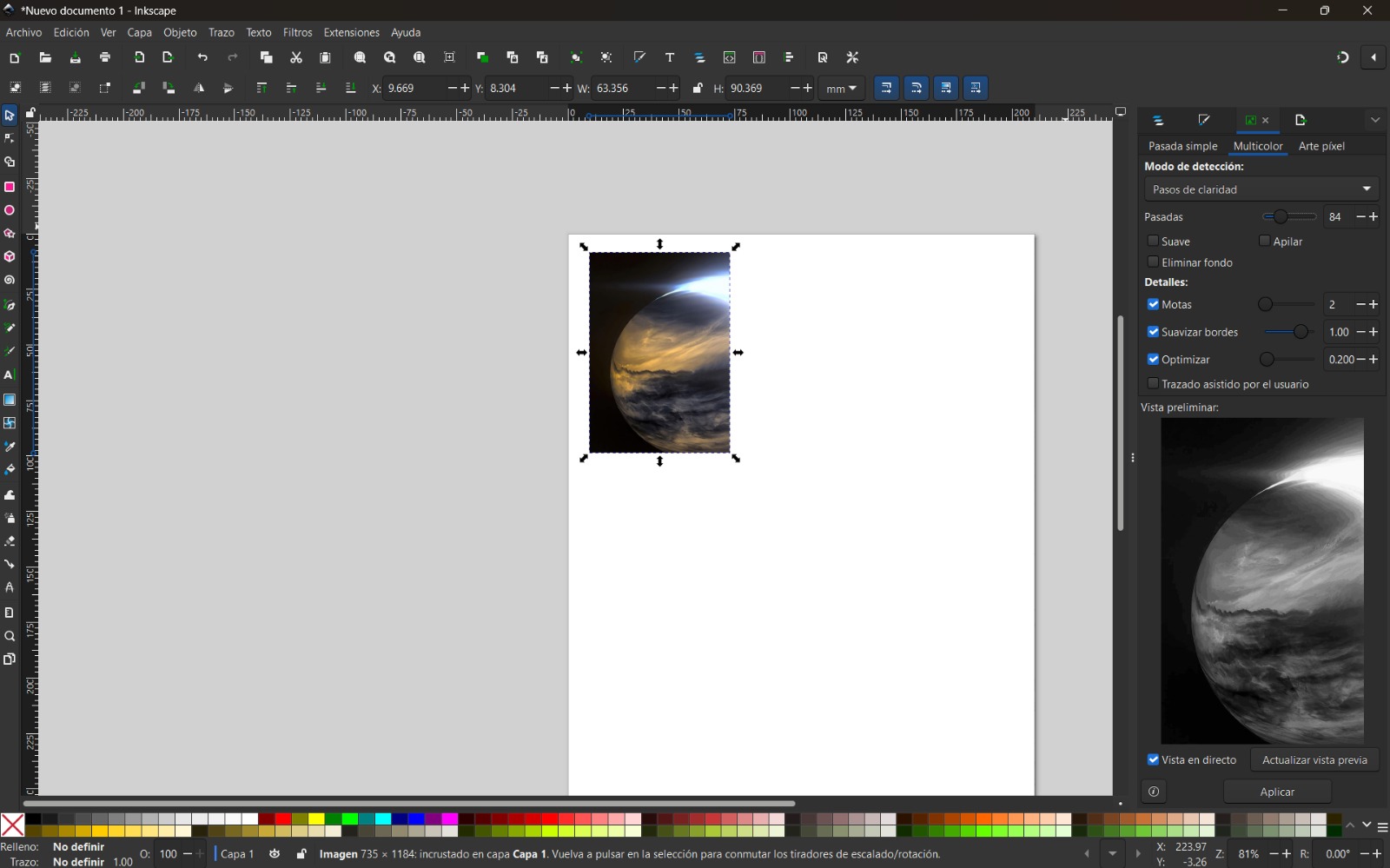
- I selected the image, right-clicked, and chose Trace Bitmap. I used the Multiple scans option with color detection to generate several vector objects from different color levels. Increasing the number of scans resulted in a more detailed image.
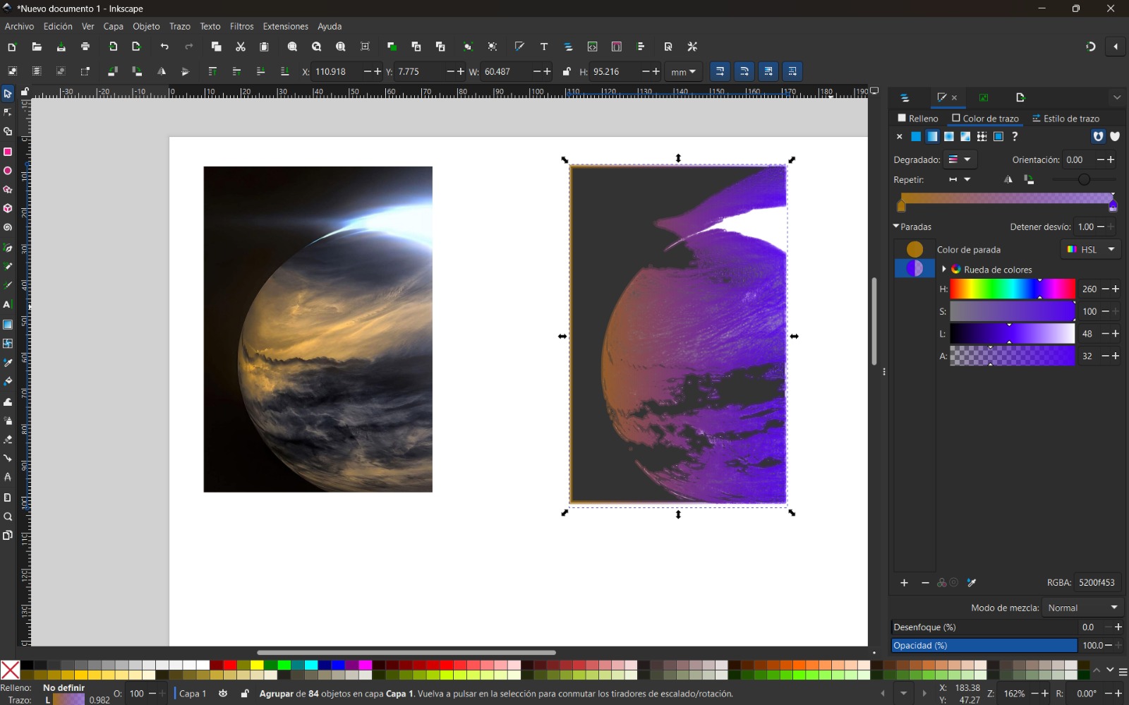
- Finally, I modified the colors according to my preferences.
Single Scan Options
- Brightness cutoff: Creates a silhouette trace
- Edge detection: Used to trace contours
- Color quantization: Traces edges between different colors
- Autotrace: Similar to brightness cutoff
- Centerline tracing (autotrace): Ideal for handwritten text
Affinity
Affinity Designer is a graphic design software that allows photo editing, vector design, and publication layout. It offers a professional workflow with advanced tools.
Basic Commands
- Ctrl + O: Open files
- Ctrl + G: Group layers or objects
- Ctrl + Alt + Shift + W: Export files
- Knife Tool: Cuts shapes or lines
- Ellipse Tool: Creates basic shapes
- Pen Tool: Draws precise paths
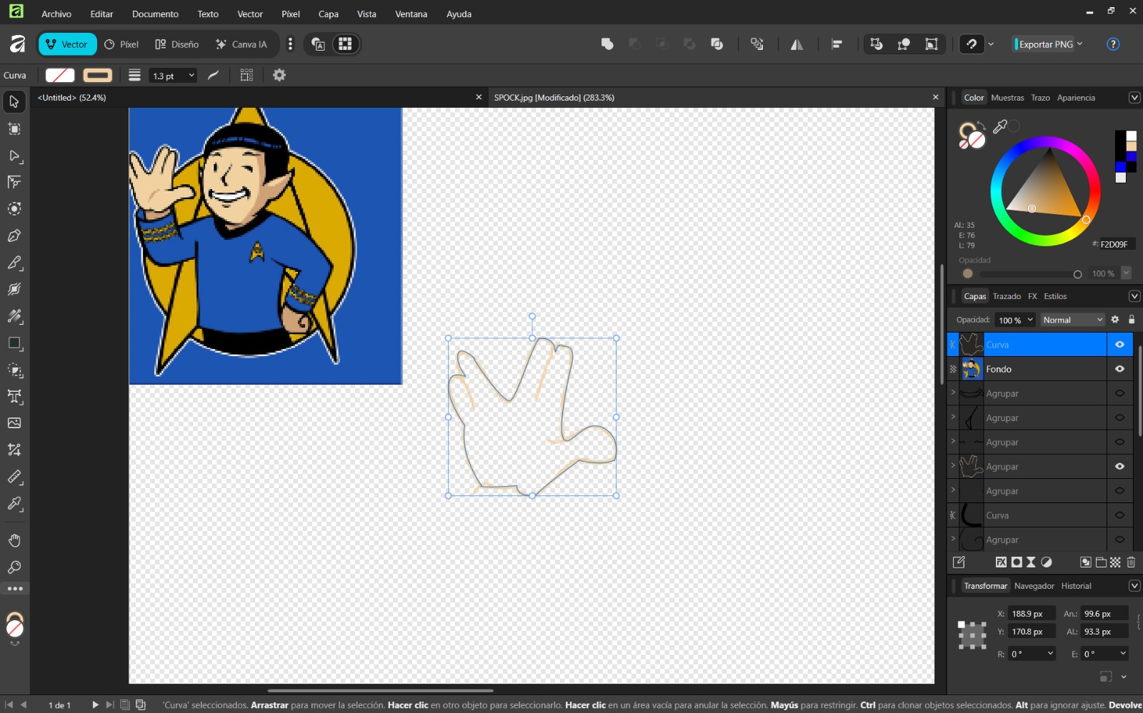
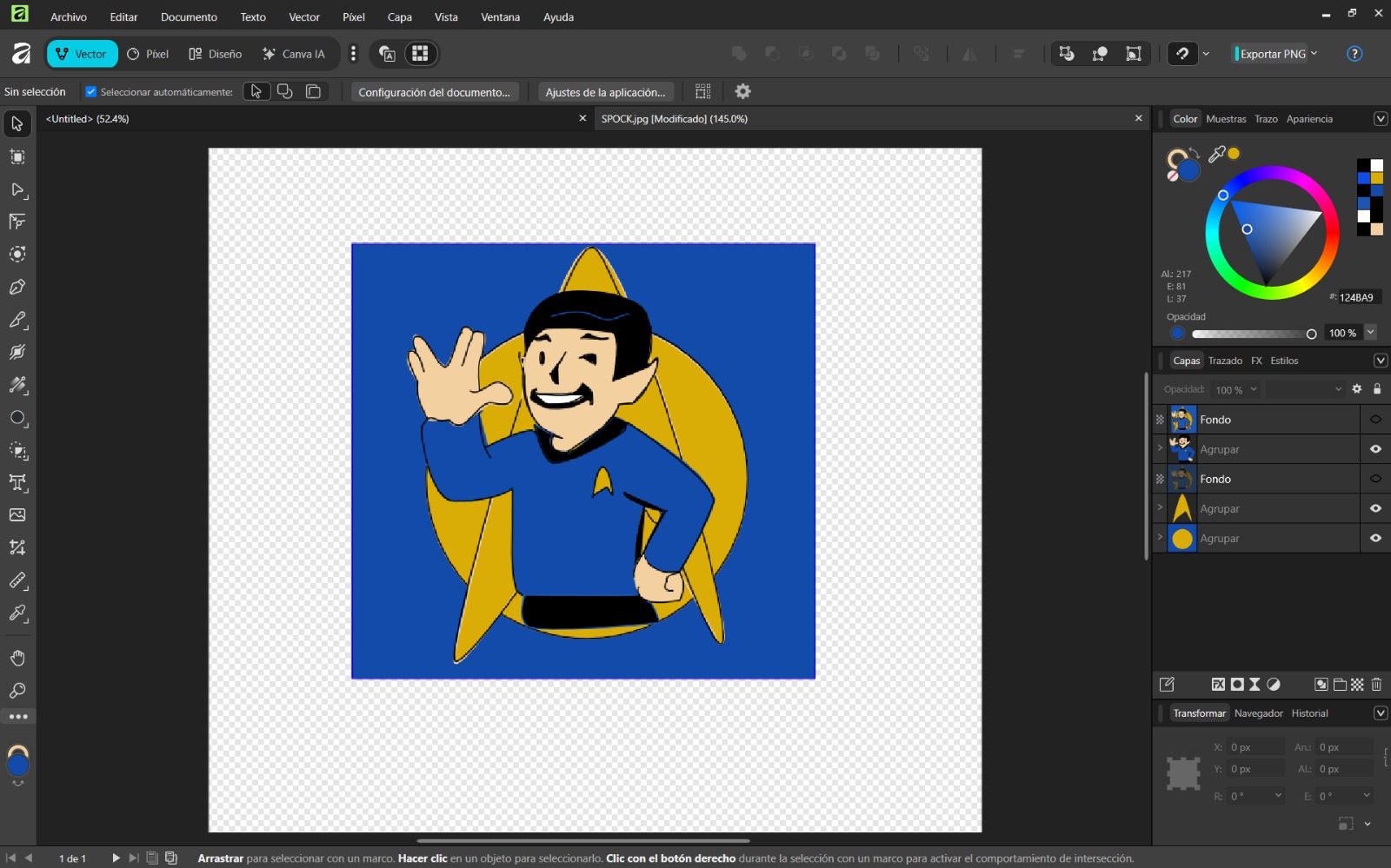
How to Use Affinity Designer – Step by Step
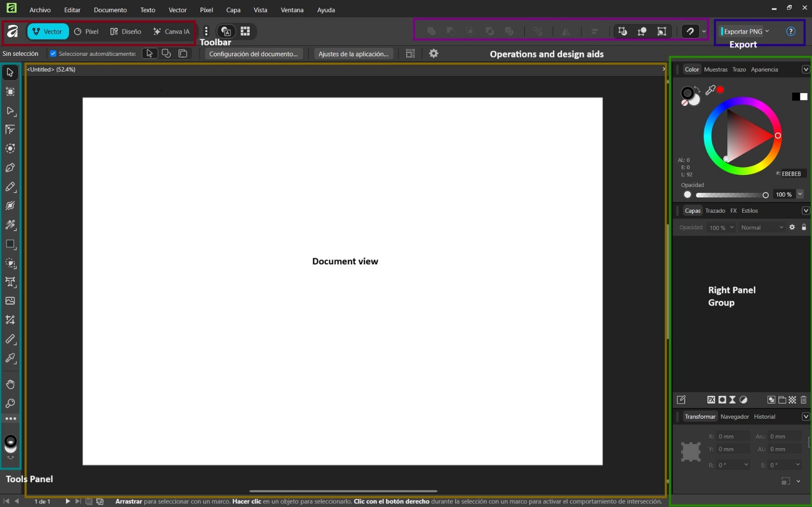
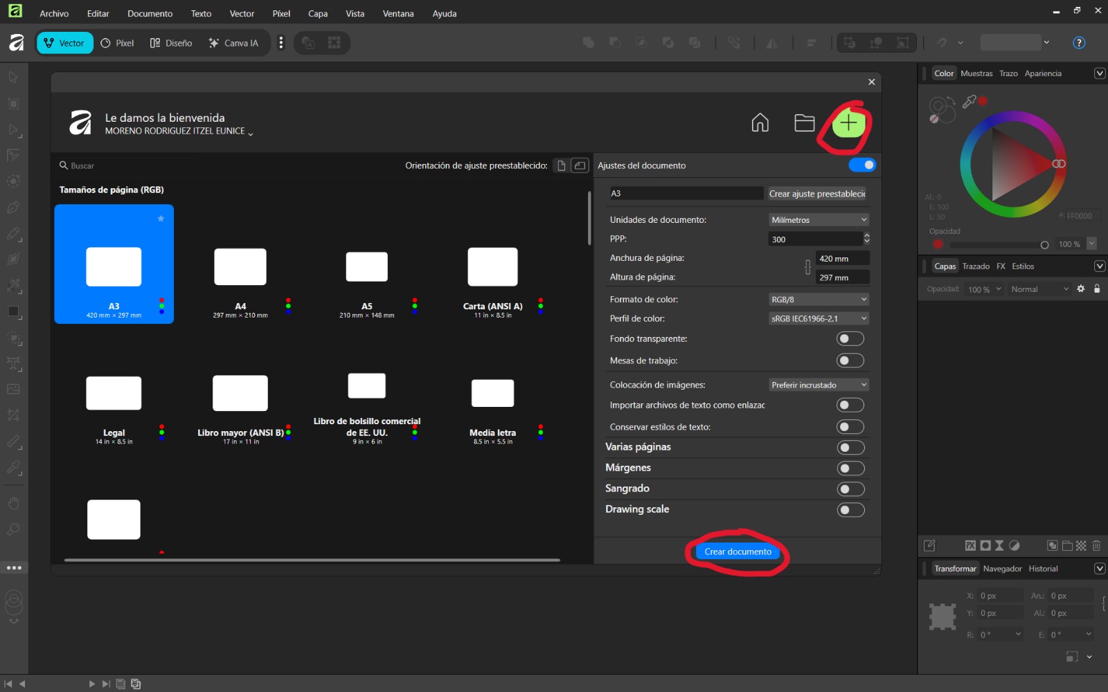
- Open the application and create a new document with the desired size.
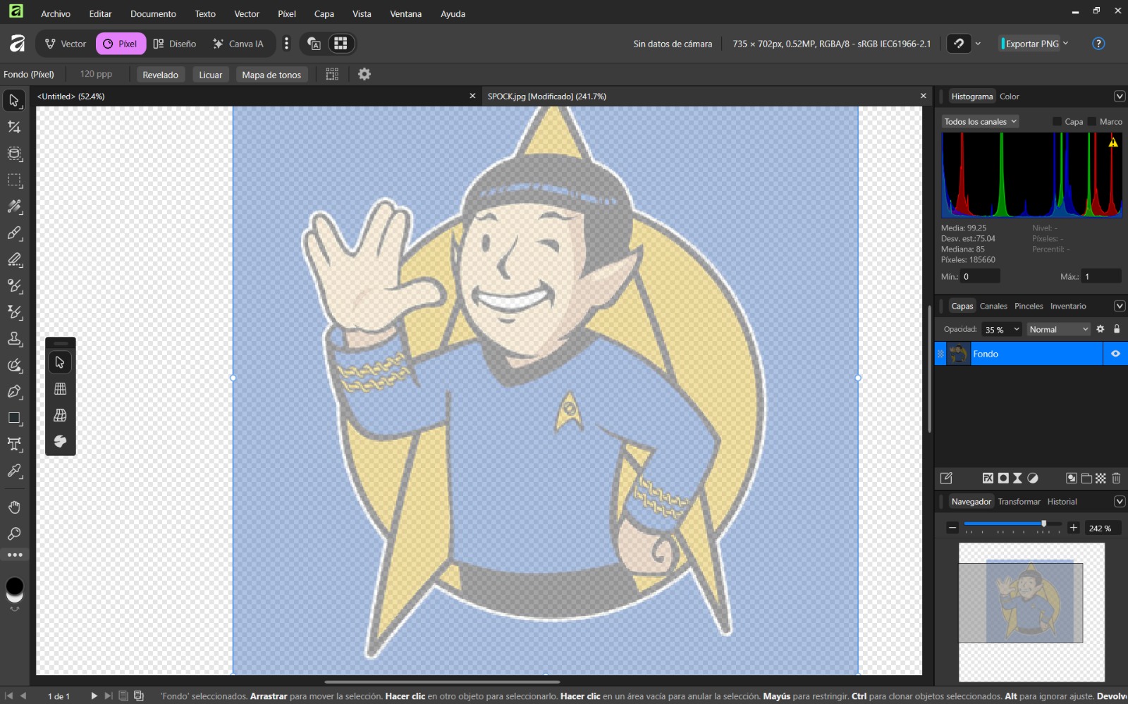
- Import a reference image using Ctrl + O and reduce opacity to 35% to use it as a guide.
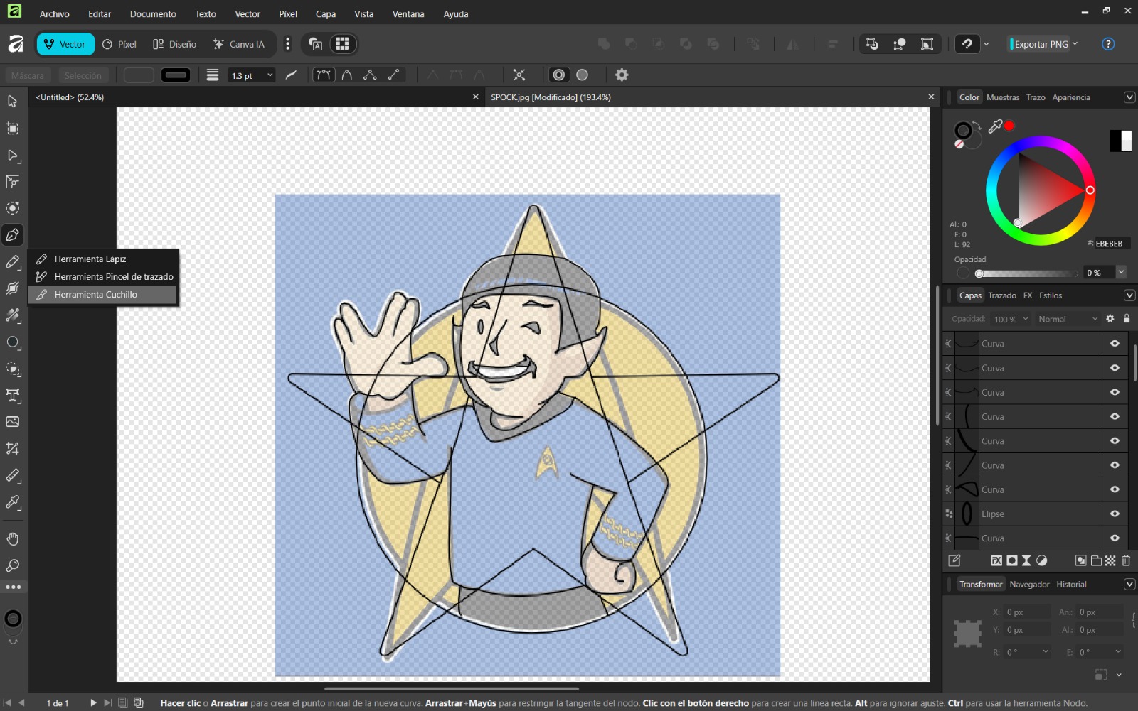
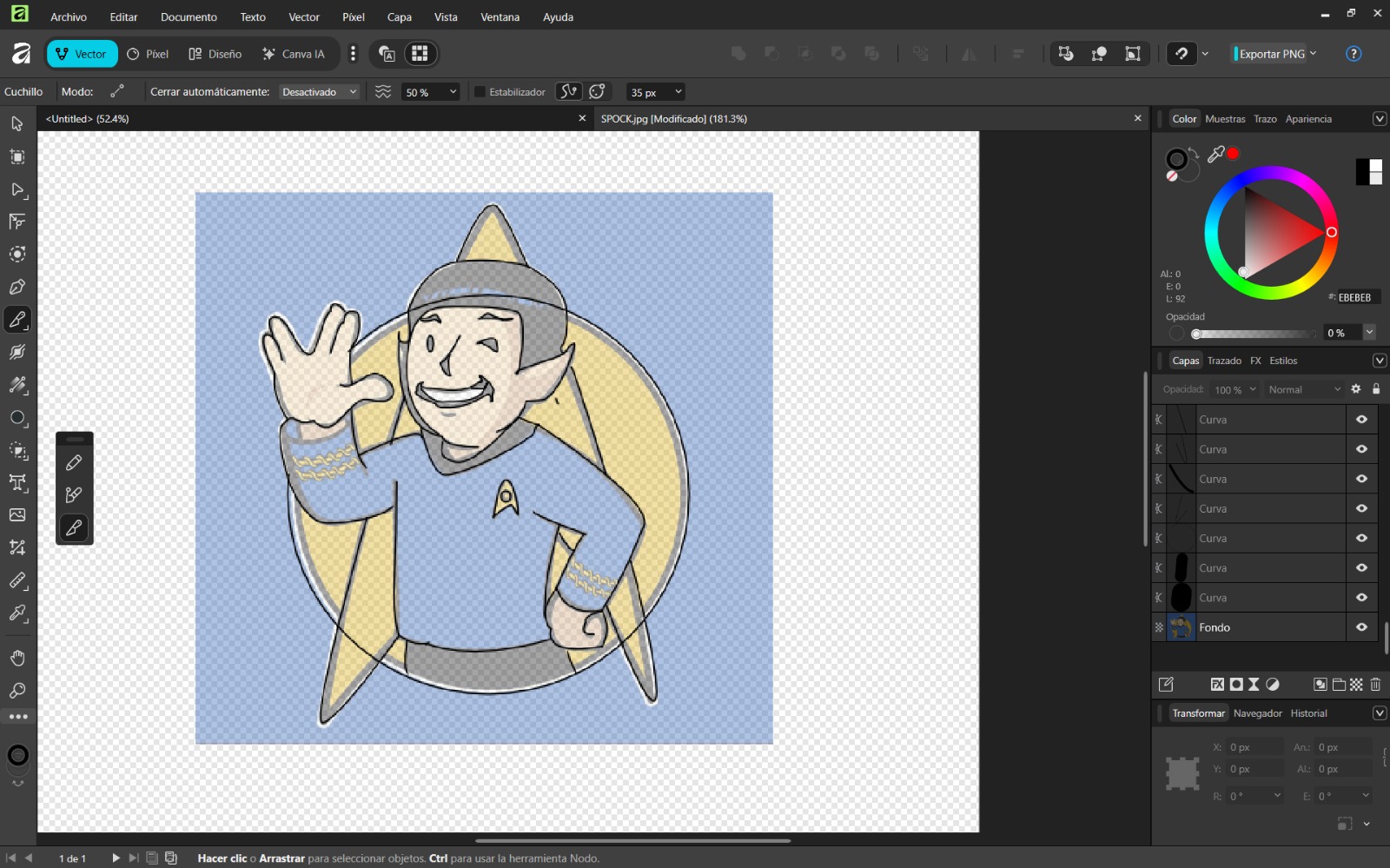
- Use shape tools for basic geometry and the pen tool for complex shapes. Remove excess areas with the knife tool.
- Group objects using Ctrl + G and apply colors.
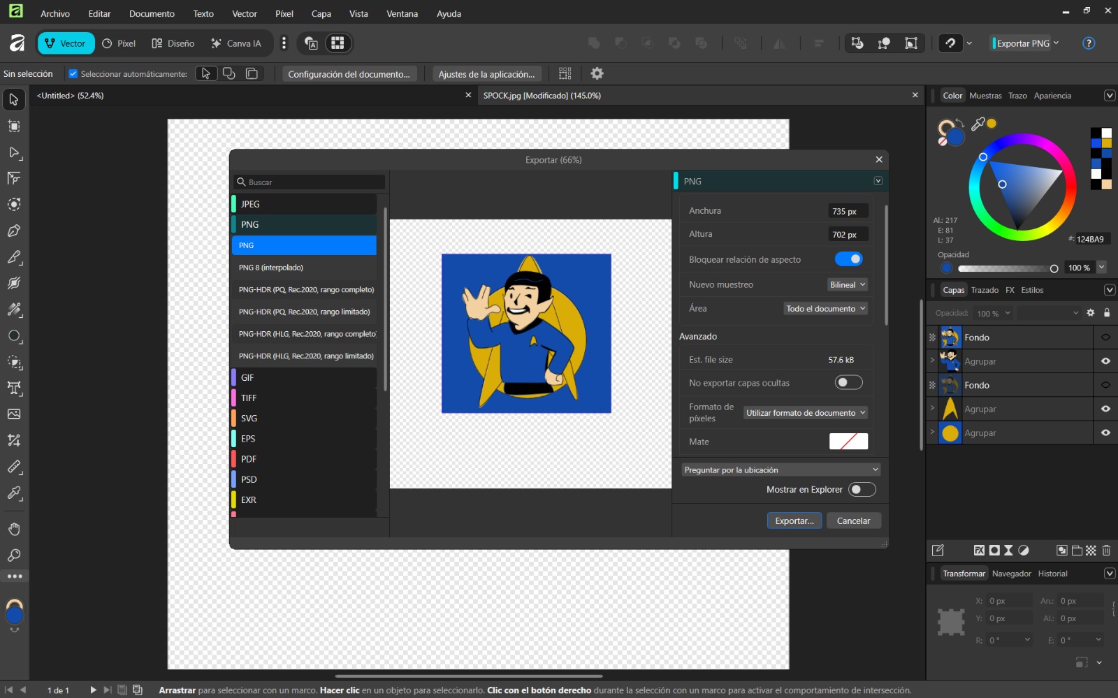
- Export the final design using File → Export and configure the desired format.
Conclusion
Both Inkscape and Affinity Designer have intuitive and user-friendly interfaces. I personally preferred Affinity Designer due to its advanced features, while Inkscape proved especially useful for image vectorization. Both are excellent tools.
Softwares en 3D
To compare the three 3D programs, I modeled the same chess pawn in each one, using different techniques and tools.
Blender
Blender Blender is a free and open-source software used for 2D and 3D modeling, animation, simulation, and rendering. It allows the creation of complex geometries and provides a wide variety of tools for detailed modeling.
Basic Commands
- Scroll: Zoom in/out
- Scroll + move mouse: Rotate view
- Shift + Scroll + move mouse: Pan view
- Add: Add new objects
- Shift + Space + S: Scale tool
- Shift + Space + Ctrl + R: Loop Cut
- Shift + Space + Ctrl + B: Bevel tool
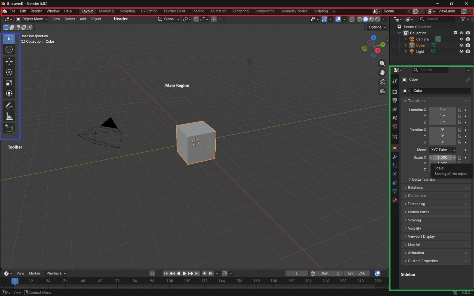
How was the piece built? Step by step
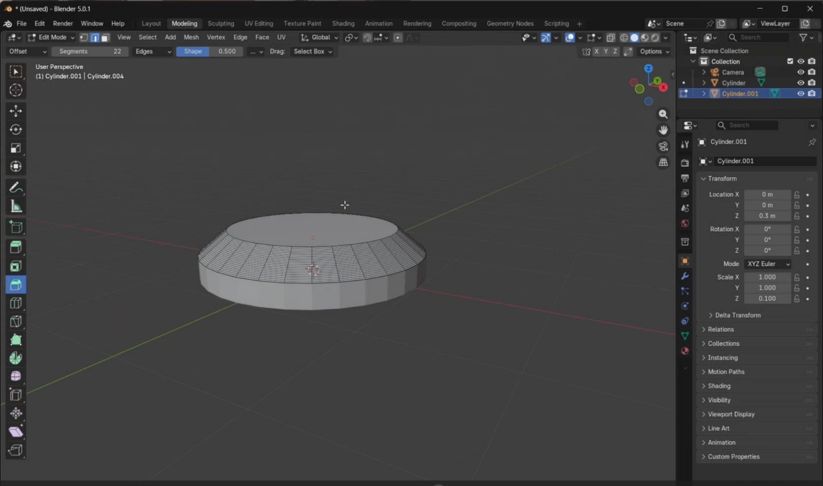
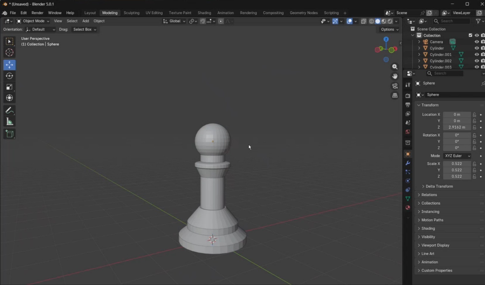
- Open Blender and delete the default cube. From the top menu, I selected Add, which displays a list of geometric primitives, and added a cylinder. Using the side panel, I adjusted its position so it was placed on top of the plane and modified its size. Then, I duplicated this cylinder and placed it on top of the first one.
- I switched from Object Mode to Edit Mode, selected Face Selection, and chose the top face of the upper cylinder. Using the Scale tool, I reduced the size of this face by scaling from the white circular handle until the desired proportion was achieved.
- Using the Loop Cut tool, I created a cut in the middle of the piece. To smooth the edges, I applied the Bevel tool and configured it with 22 segments. Increasing the number of segments results in smoother edges but increases rendering complexity. After this, I returned to Object Mode.
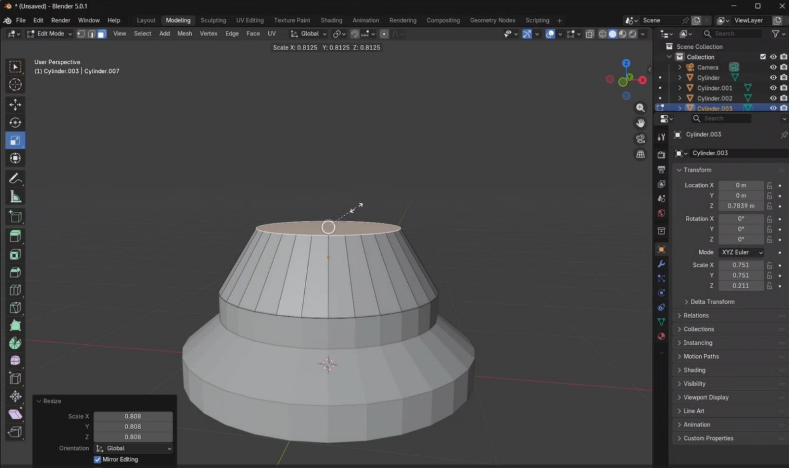
- I added a new cylinder and adjusted its dimensions to match the size of the object below it. This cylinder was duplicated and scaled to create the curved body of the chess piece.
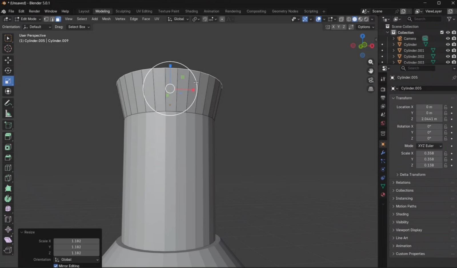
- Another cylinder was created with similar dimensions and elongated using the Scale tool. Then, I added an additional cylinder and scaled its top face to make it wider.
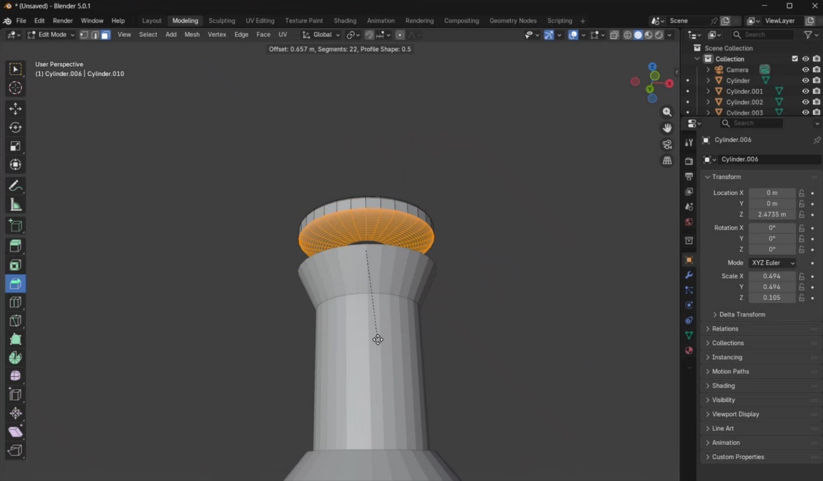
- I added a final cylinder, reduced it to the required dimensions, and applied beveling on both faces to obtain the desired rounded effect for the piece.
- Finally, I completed the model by adding the remaining elements required to finish the pawn geometry.
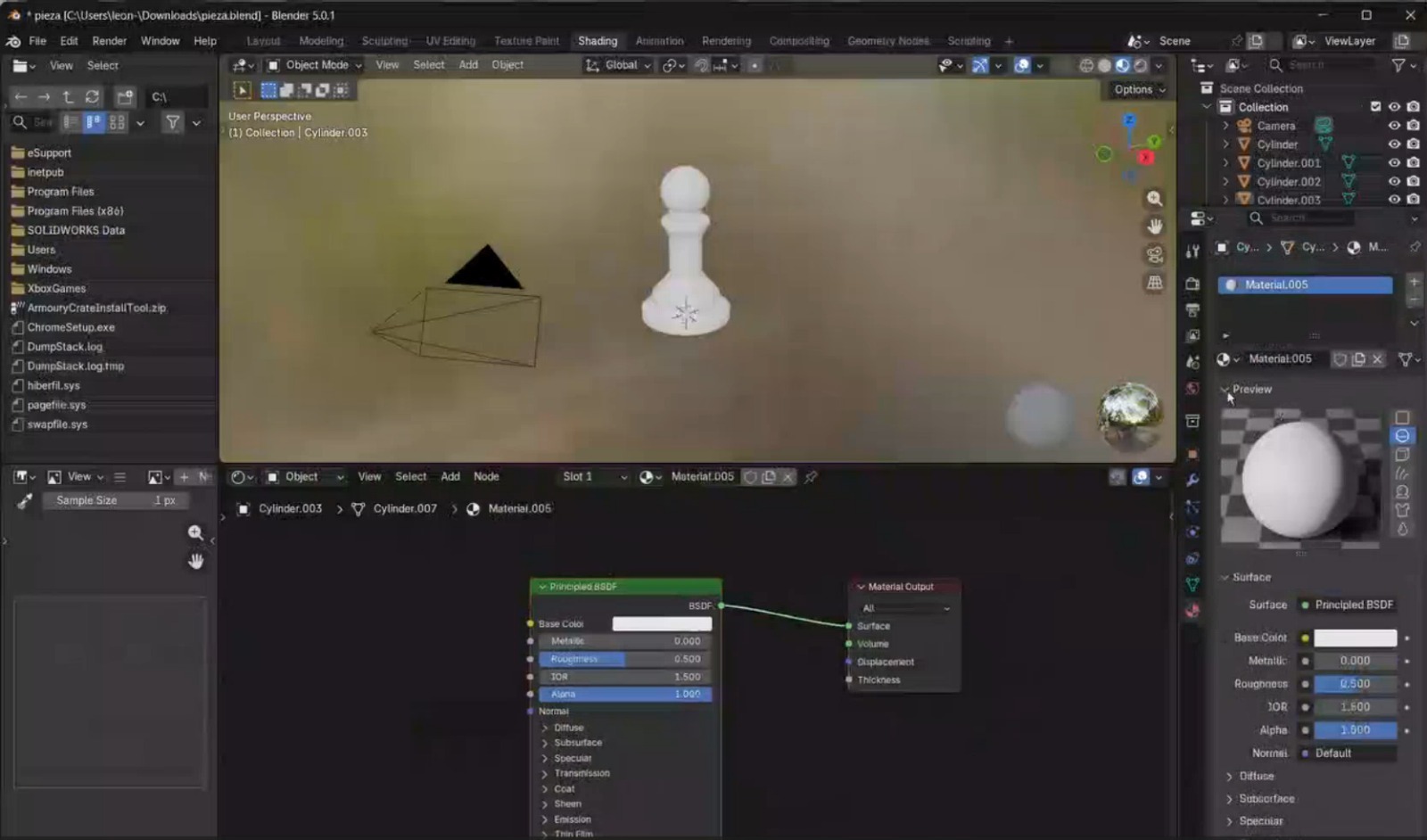
- To add textures, I switched to the Shading tab and enabled the Node Wrangler add-on by navigating to Edit → Preferences → Add-ons and activating it. Then, in the Material section, I added a new material, selected the green shader node, and pressed Shift + Ctrl + T to load the texture files. The textures used in this project were downloaded from Poly Haven

OnShape
OnShape is a cloud-based CAD system that operates on any device. Since it runs entirely online, data is not lost. It offers multiple advantages, such as no required installations, the ability to work on designs through simultaneous collaboration, and access to a wide range of advanced features. The software is completely free, although creating an account is required.
IMAGEN
Additional information can be found here:
Basic Commands
- Shift + S:Create a new sketch.
- Shift + Right Click + Drag: Pan view
- Scroll: Zoom in/out
- L: Line tool
- R: Rectangle tool
- C: Circle tool
- Spline: Allows the creation of curved lines.
- Shift + E: Activate the extrusion tool.
- Shift + W: Activates the revolve tool, which allows the creation of a solid or surface by revolving a 2D sketch around an axis.
- M: Activates the Trim tool for cutting sketch elements.
How was the piece built? Step by step
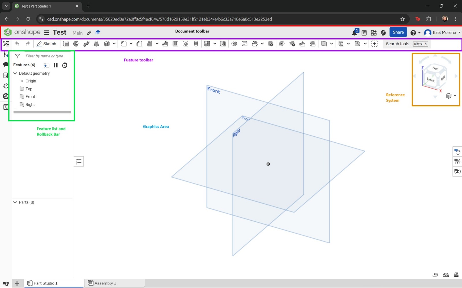
- First, access the Onshape website and log in to your account.
- Select Create and then Document to create a new part. In this section, the document name can be assigned. Once completed, select Create.
- The main interface will appear, displaying the reference planes. A new sketch was created, and the plane to work on was selected. In my case, I chose the Top plane.
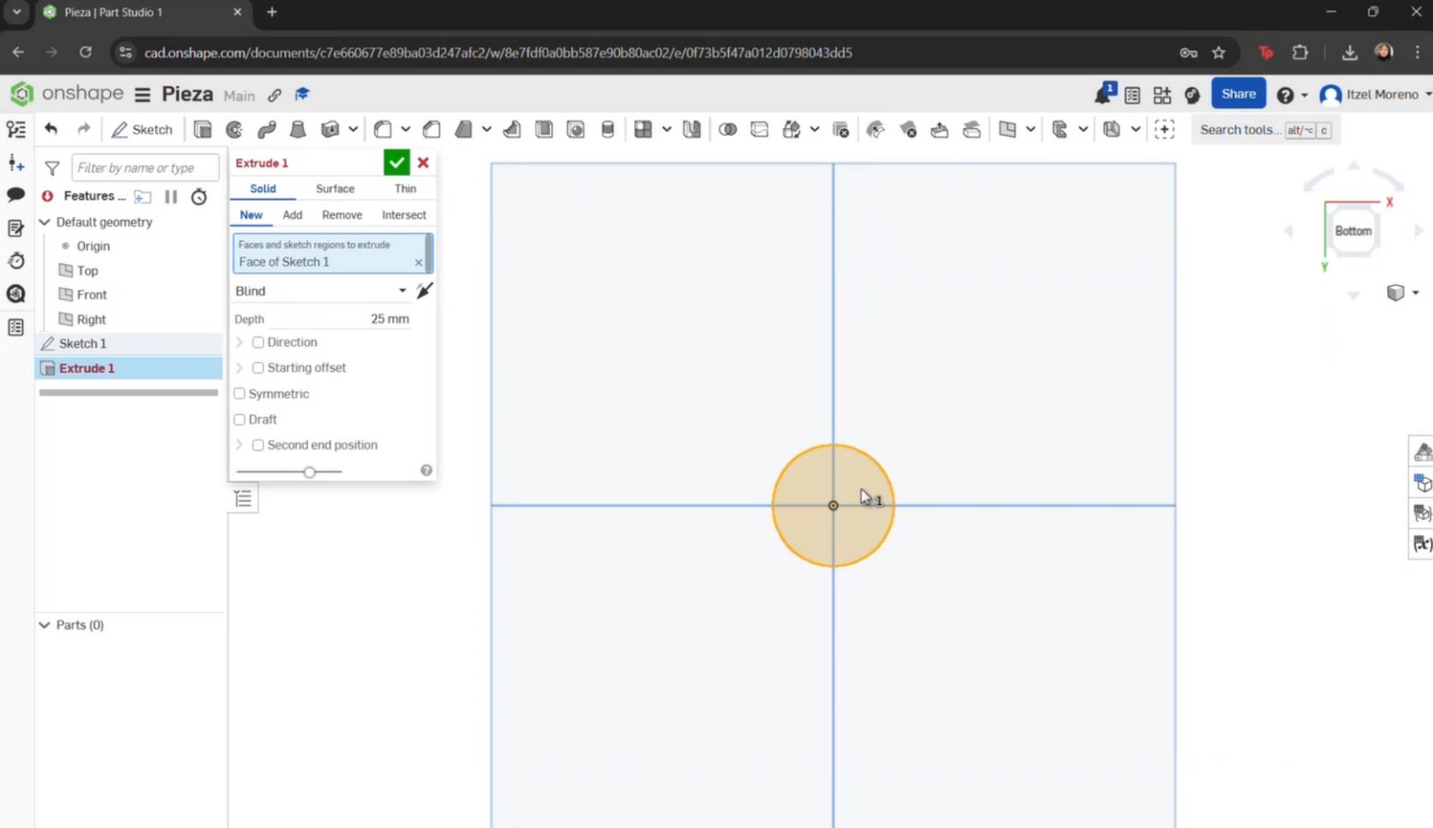
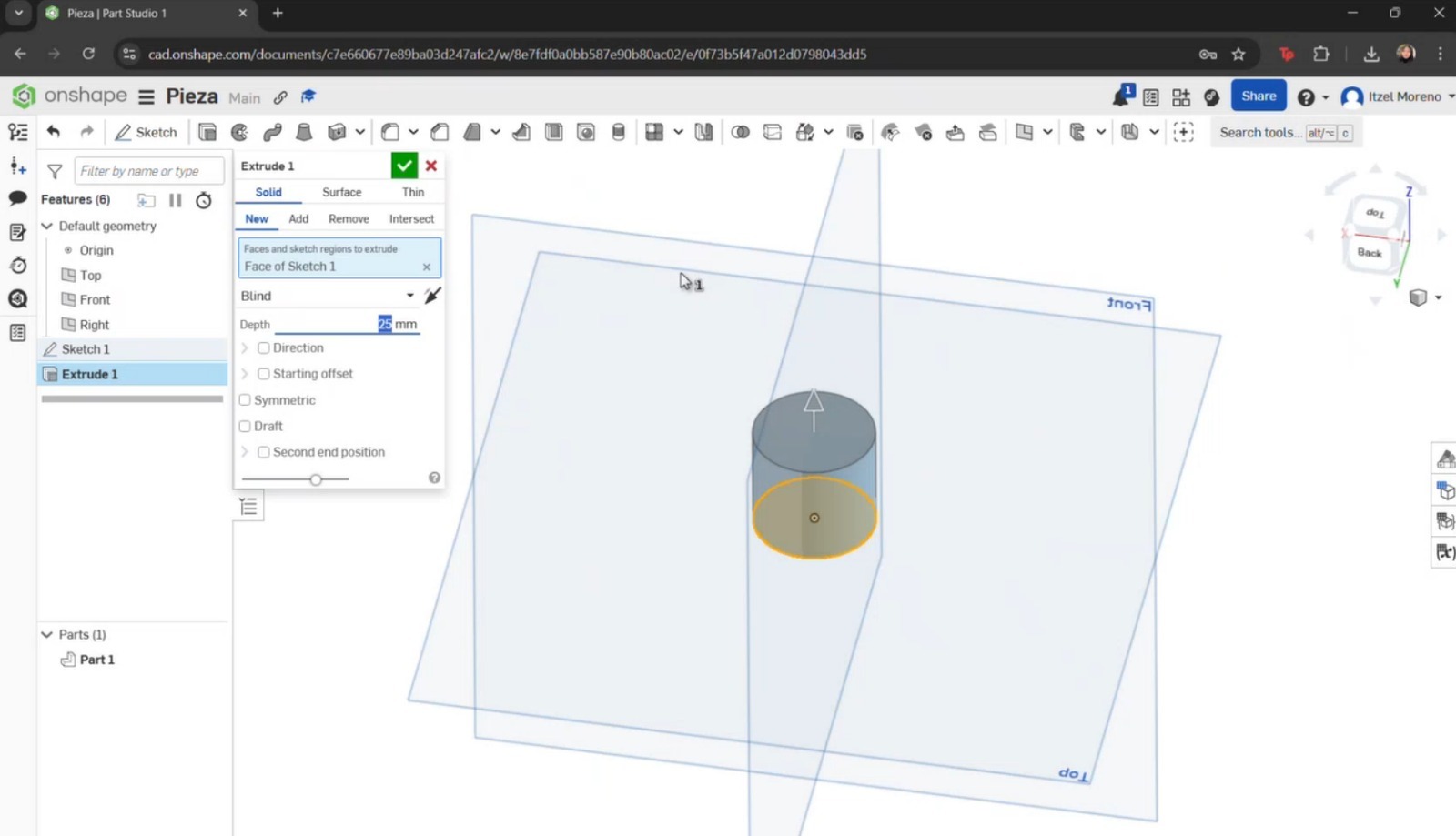
- I began by creating a circle starting from the center. Dimensions were then assigned. Once completed, the green checkmark was selected to save the sketch.
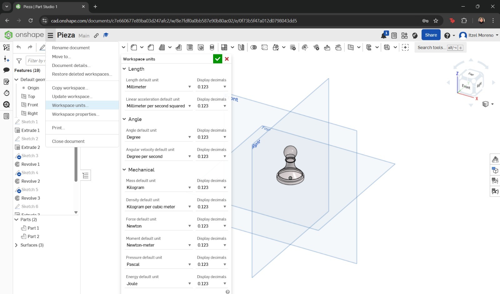
- If unit changes are required, the menu icon with three horizontal lines can be selected to display additional options. From there, Workspace units can be chosen and adjusted according to preference.
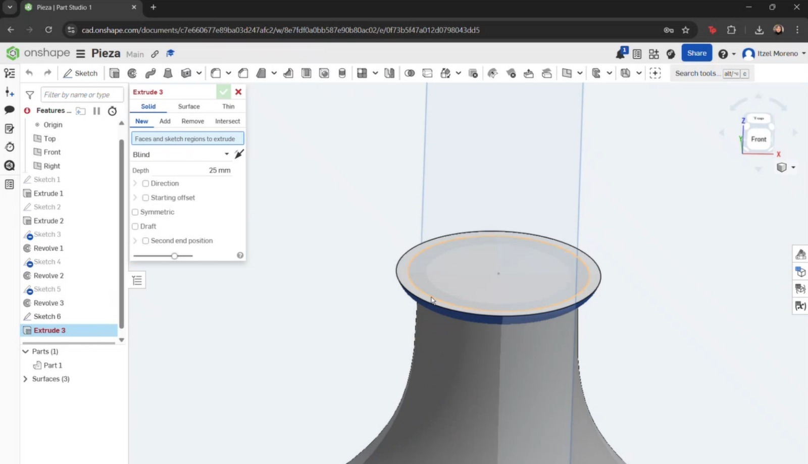
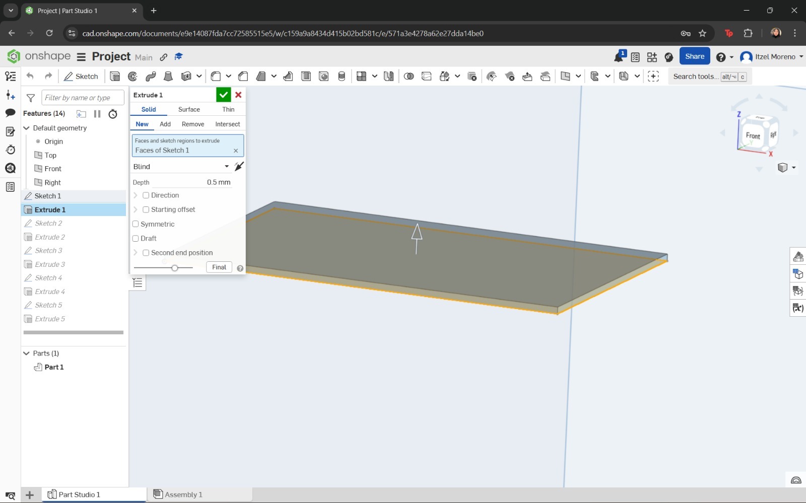
- The Extrude tool was selected, along with the sketch to be extruded, and the desired dimensions were applied.
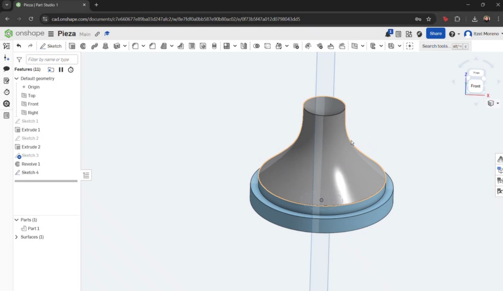
- Another sketch was created on top of the extrusion, where a circle was drawn, dimensioned, and extruded again. To create the curvature of the pawn, a new sketch was made by selecting the Right plane. Working only on half of the axis, the Line tool was used to draw a straight line at the top with fixed dimensions. Then, the Spline tool was used to create the pawn’s curvature.
- The same previous steps were repeated, modifying the curvature as required.
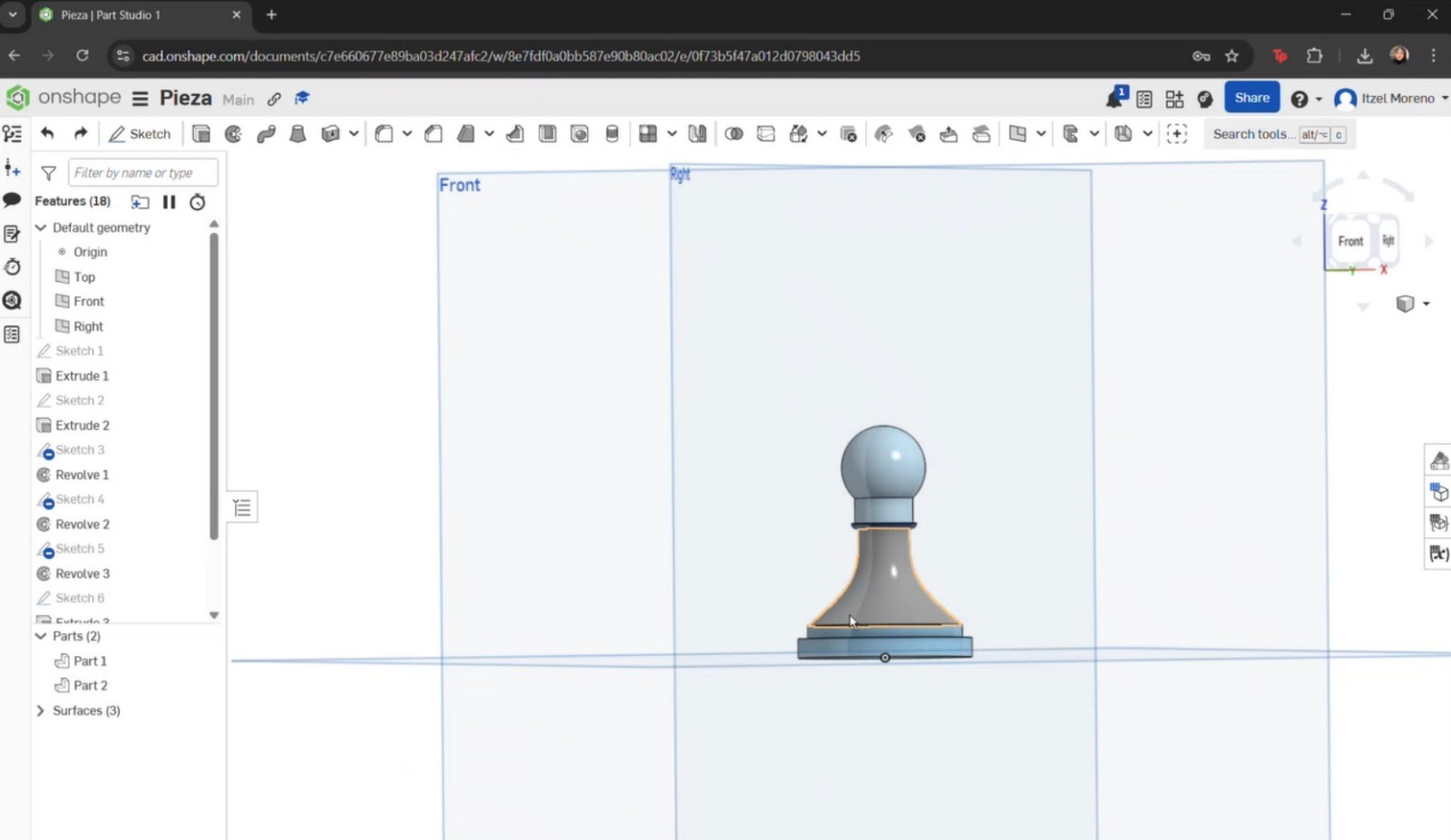
- In a new sketch, a straight line was drawn to create a solid base beneath the previous components. A new plane was then created on top of this base to model the remaining parts of the piece. This process was continued until the rest of the pawn was completed.
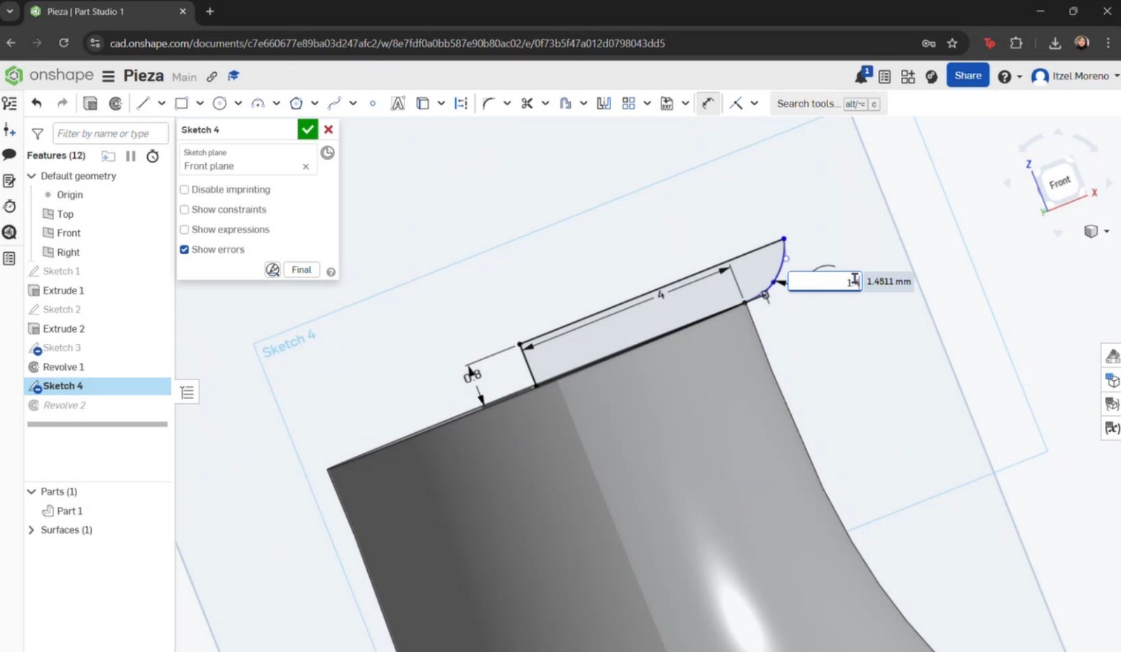
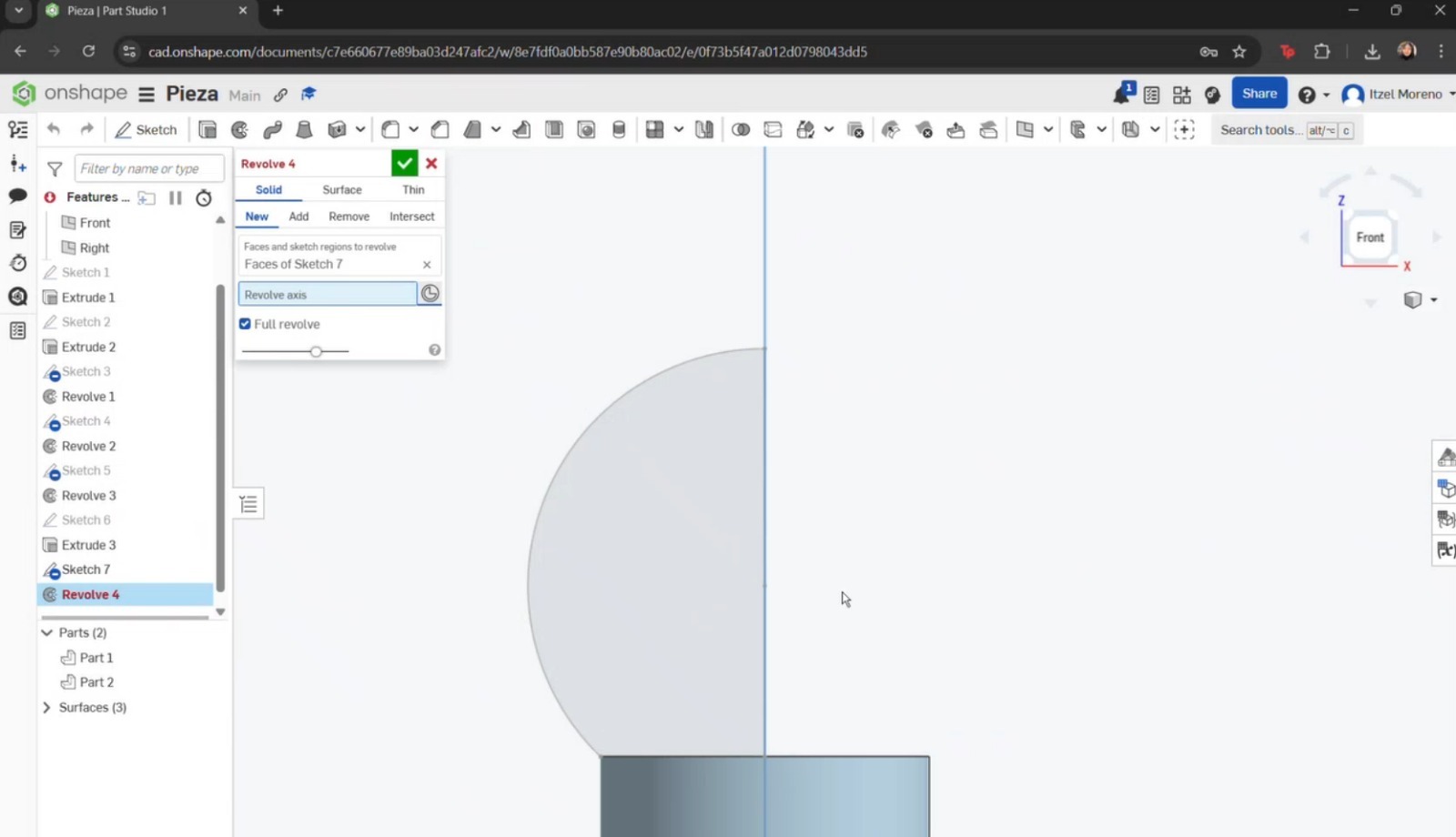
- To create the head of the pawn, the arc or spline tools could have been used; however, the circle tool was chosen as it provided a simpler approach. A straight line was then placed through the center, and the excess portion of the circle was trimmed in order to perform a revolution.
- To add textures, in the Parts section, right-click on the part to display the options menu. Then select Assign material and choose the desired material.
.jpeg)
Finally, a straight line was added to close the sketch. Once completed, the Revolve tool was used by selecting Surface, the curve to be revolved, and the axis (circle) around which the revolution was performed.
SolidWorks
SolidWorks is a 3D design software used for creating parts, assemblies, and simulations. It provides a comprehensive set of tools that enable efficient product development and design optimization. A license is required to use this software.
Basic Commands
- Front View: Front projection of the part.
- Top View: Top projection of the part.
- Side View: Side projection of the part.
- Line: Creates straight line segments.
- Rectangle: Creates rectangular geometries.
- Circle: Creates circular geometries.
- Spline: Creates curved segments.
- Dimension: Used to dimension sketches.
- Trim Entities: Removes unwanted sketch elements.
- Extruded Boss/Base: Creates 3D geometry from 2D sketches.
Additional keyboard shortcuts can be found HERE!
How was the piece built? Step by step
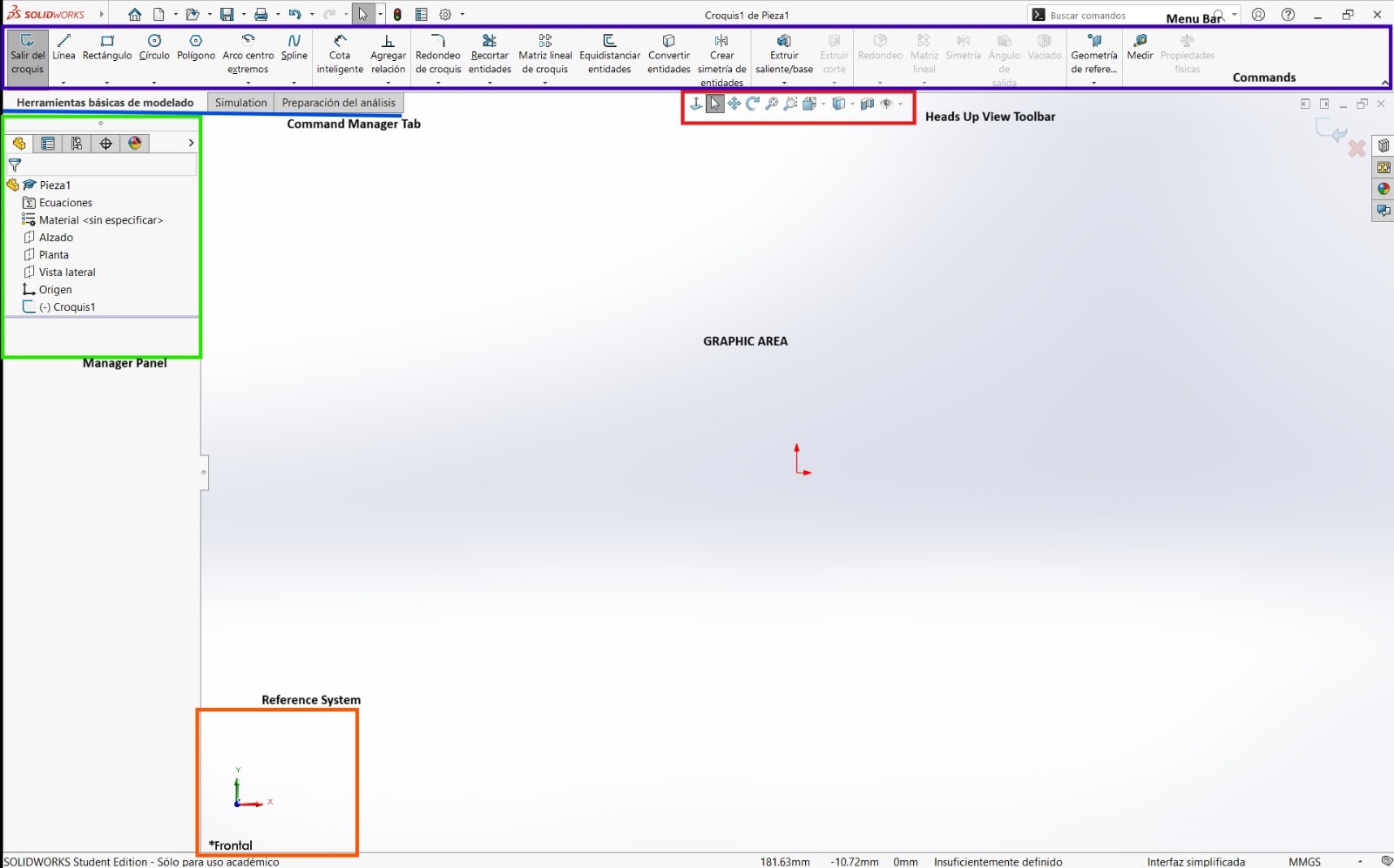
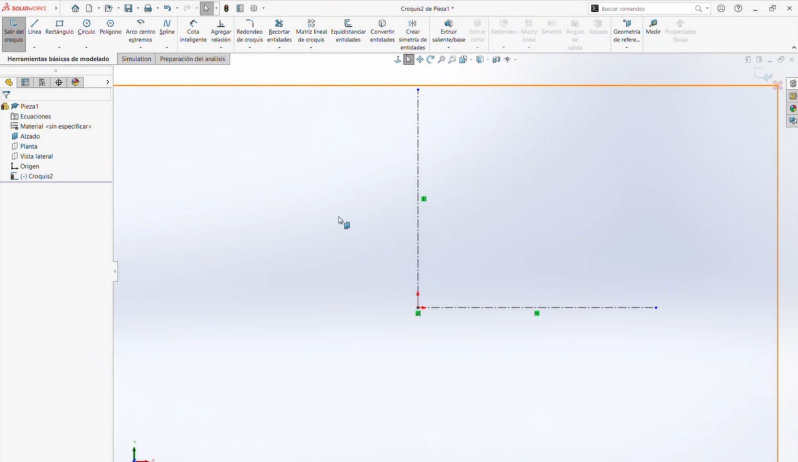
- Open SolidWorks and create a new part document.
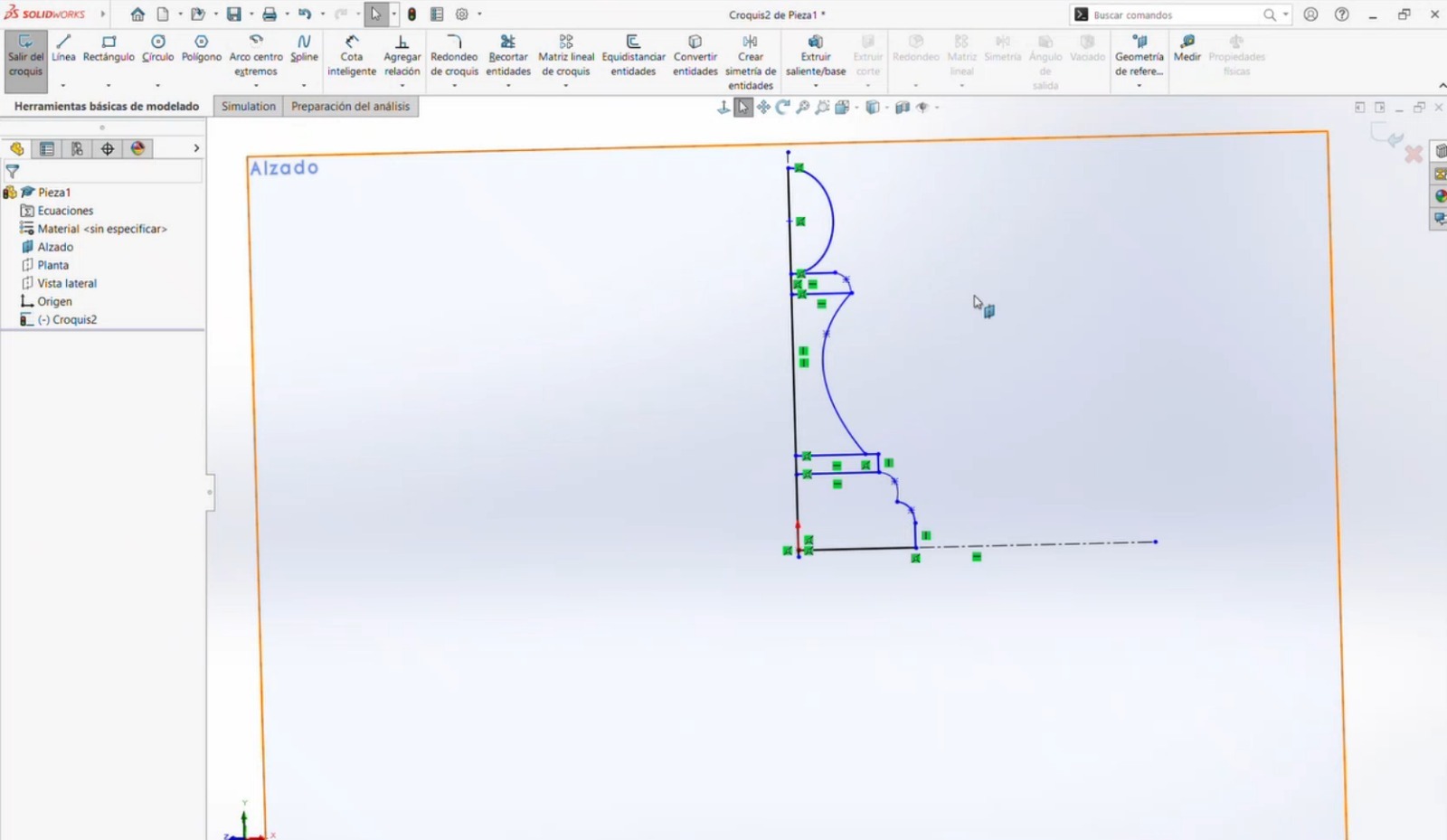
- A sketch was created in the Front Plane. The design process began with simple shapes, which were later refined. Construction lines were added as references. A circle and two rectangles were created, and the Spline tool was used to connect the geometries. Straight lines were then added to close the shape. Half of the sketch was trimmed, leaving only one side for a revolution operation.
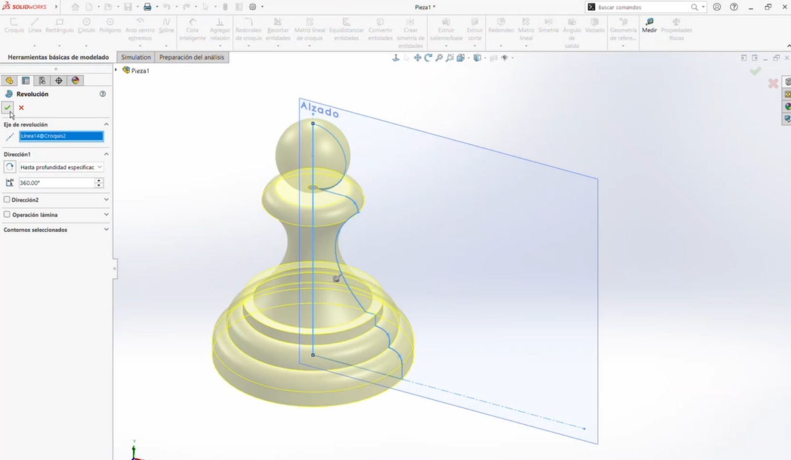
- The completed sketch was selected, the Revolve feature was applied, and the central axis was chosen to generate the 3D geometry.
Conclusion
All three programs provide intuitive tools and interfaces; however, different techniques were required in each one. In my experience, Blender was the most challenging software, while SolidWorks allowed a more straightforward modeling process. Blender requires more time to learn due to its complex tools. On the other hand, both SolidWorks and Onshape were my preferred tools for 3D modeling. Among them, Onshape felt more intuitive to me, although both are excellent platforms for creating 3D models.
Compress images and videos
Compress videos with FFMPEG
To compress images and videos, I used FFMPEG
Basic Commands
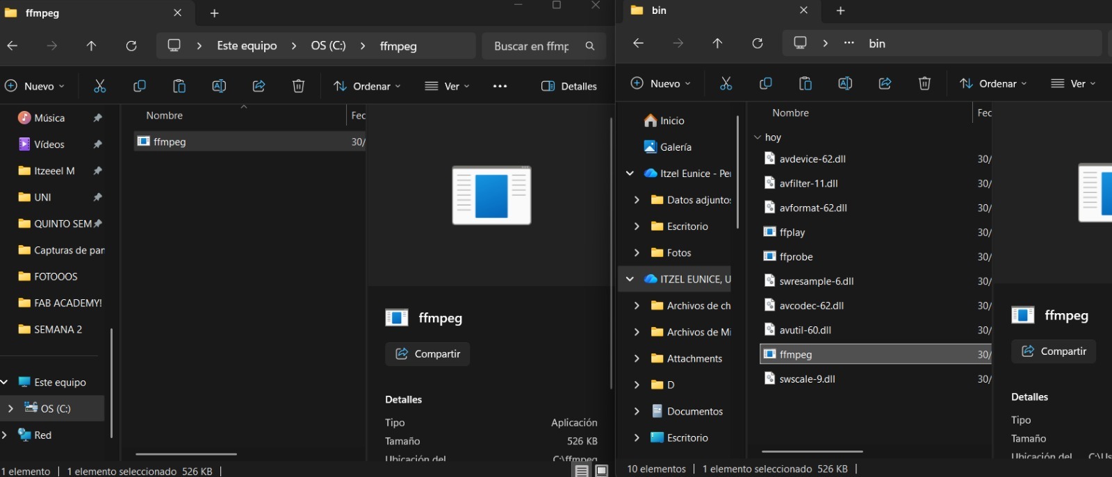
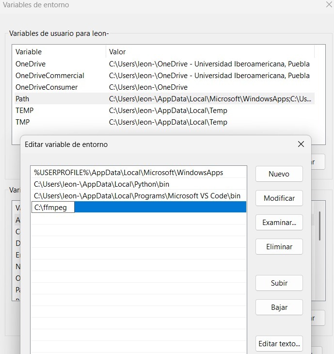
- Download Windows builds by BtbN. Once the program was downloaded, a folder was created on the computer’s main hard drive. The compressed file was then extracted, and the files from the folder named bin were copied.
- The following path was accessed: System Settings → Advanced System Settings → System Properties → Environment Variables. Once the Environment Variables option appeared, a new variable was created, and the directory path of the corresponding program folder was added. The changes were then confirmed.
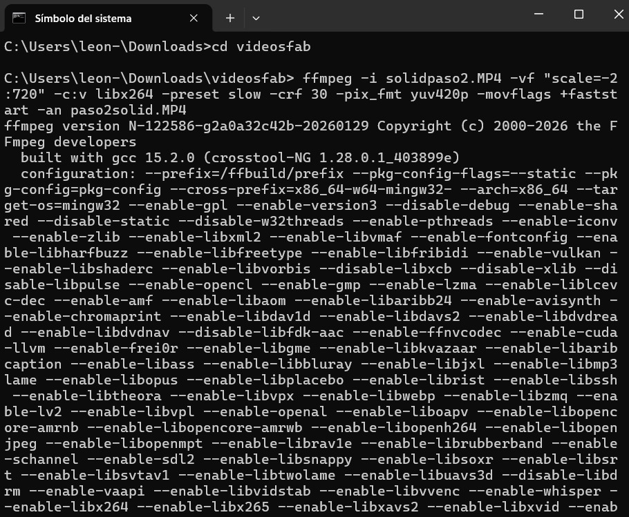
- Open Command Prompt and run FFMPEG from the terminal.
- In my case, I added the path to the folder where my video file was located and executed the following command:
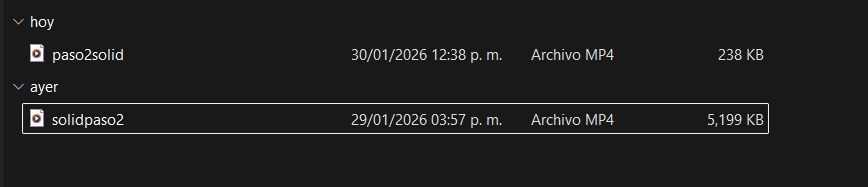
ffmpeg -i NOMBRE DE VÍDEO -vf “scale=-2:720” -c:v ibx264 – preset slow -crf 30 -pix_fmt yuv420p -movflag +faststart -an NOMBRE DEL ARCHIVO.mp4 - Finally, the video was compressed from 5,199 KB to 238 KB
Parameters
- vf: Video scaling
- c:v: Video codec
- preset: Compression speed
- crf: Video quality (lower = better quality)
- pix_fmt: Browser compatibility
Compress images with Inkscape
I found very useful using Inkscape to compress images and it is simple to use. I had to follow the next steps:
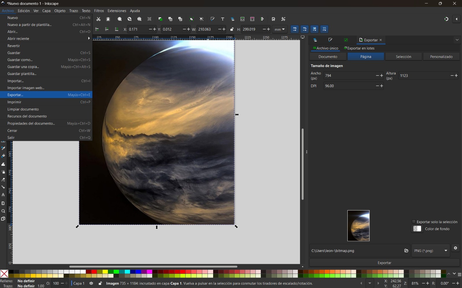
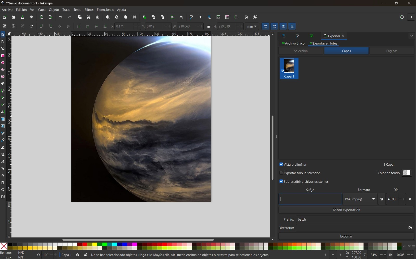
- Open Inkscape and import the image you want to compress.
- Go to File → Export As → Export PNG.
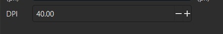
- In the export dialog, adjust the DPI and compression settings. Also, don't forget to change the type of image's format for the one you prefer.
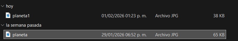
- Click Export and save the compressed image. In this way, you can observe that I reduced the size of the image from 65 KB to 38 KB.
Project Design
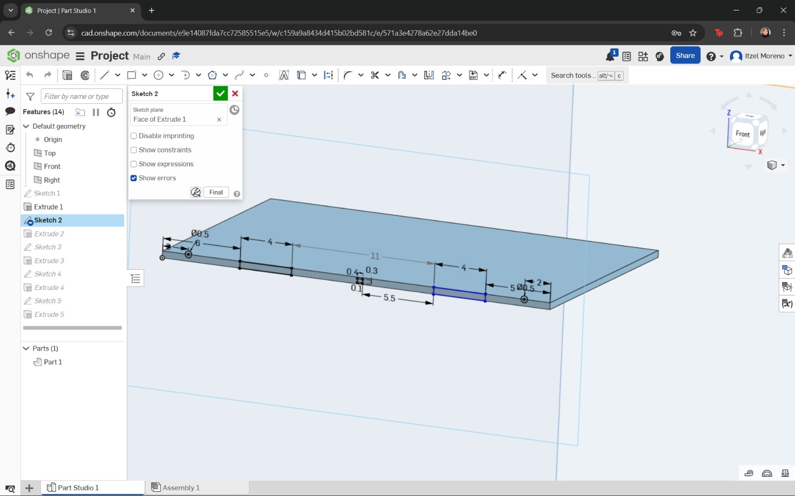
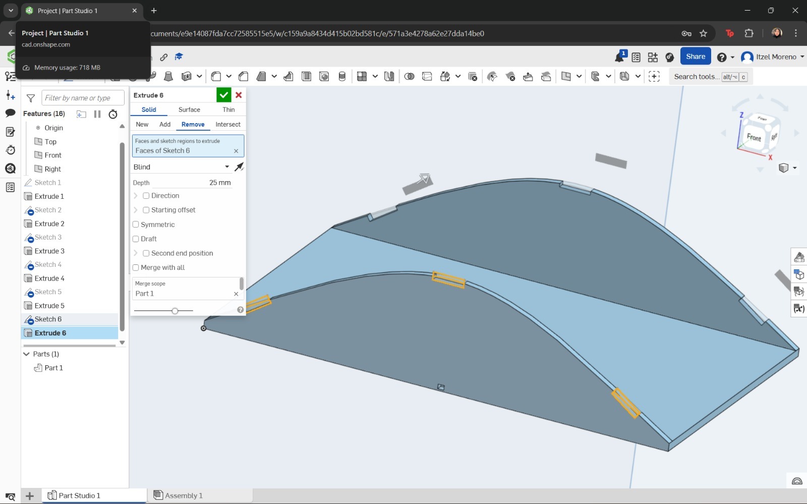
- I decided to begin with the robot chassis. For this purpose, I used Onshape. I opened a new document and created a sketch using the dimensions I considered appropriate.
- Next, a curvature was created on the same plane to form the walls of the robot chassis. The previously defined geometries required for assembly were respected.
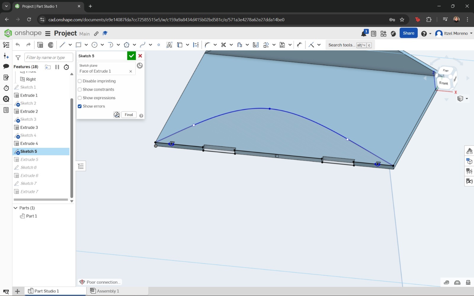
- The same procedure described in the previous step was repeated on the opposite side of the plane.
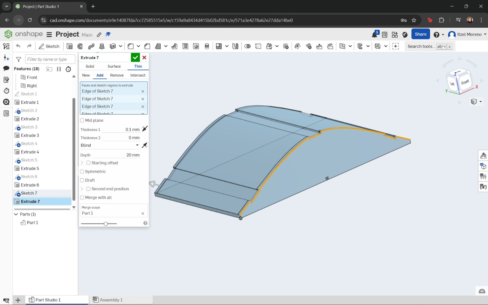
- Afterwards, the curved shape of the top cover was drawn using the Spline tool and extruded.
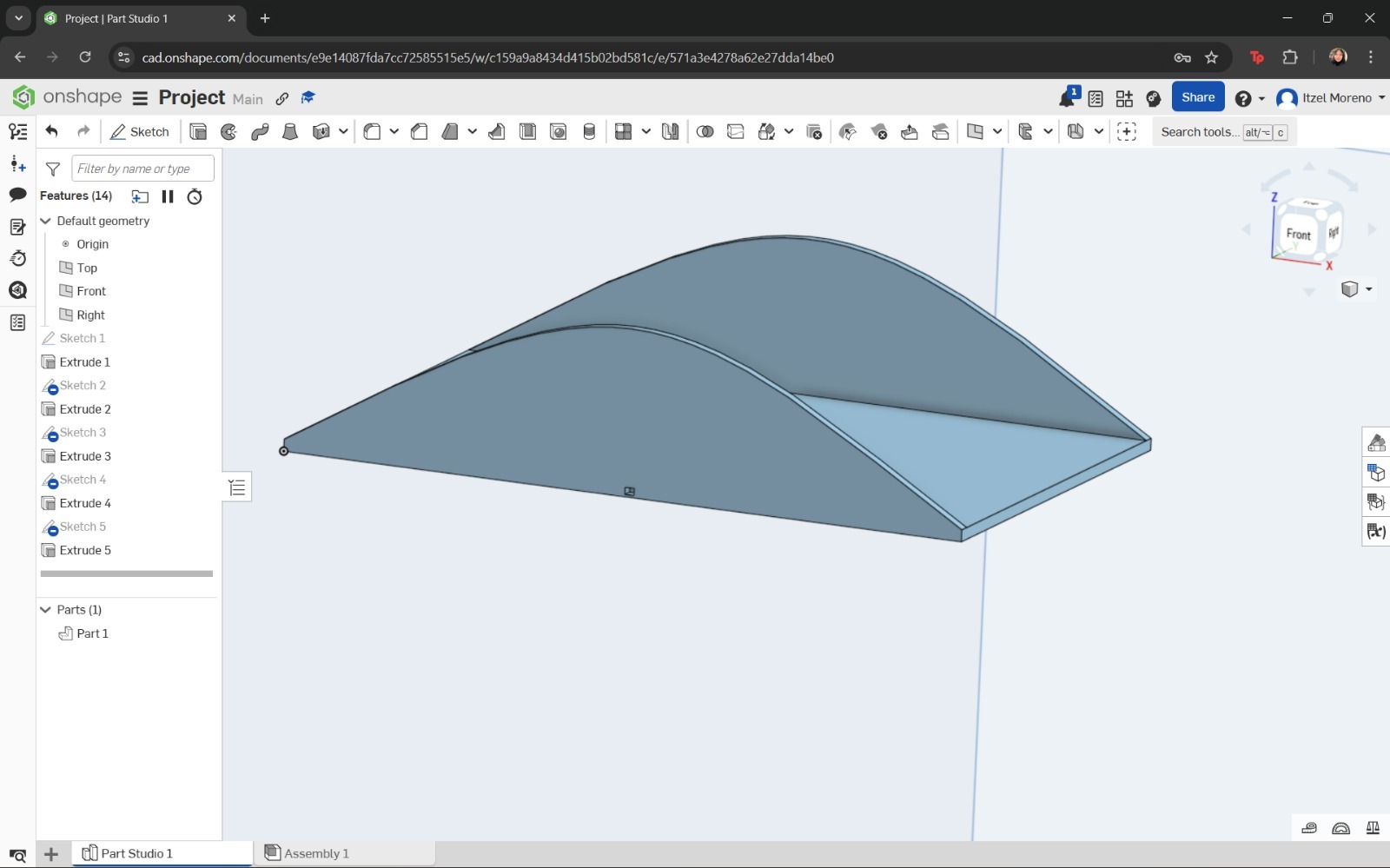
The sketch was then extruded to create the base of the structure. At this stage, the chassis was designed to allow proper assembly.
In this step, the Spline and Line tools were used to draw the profile. Finally, this sketch was extruded to a thickness of 5 mm.
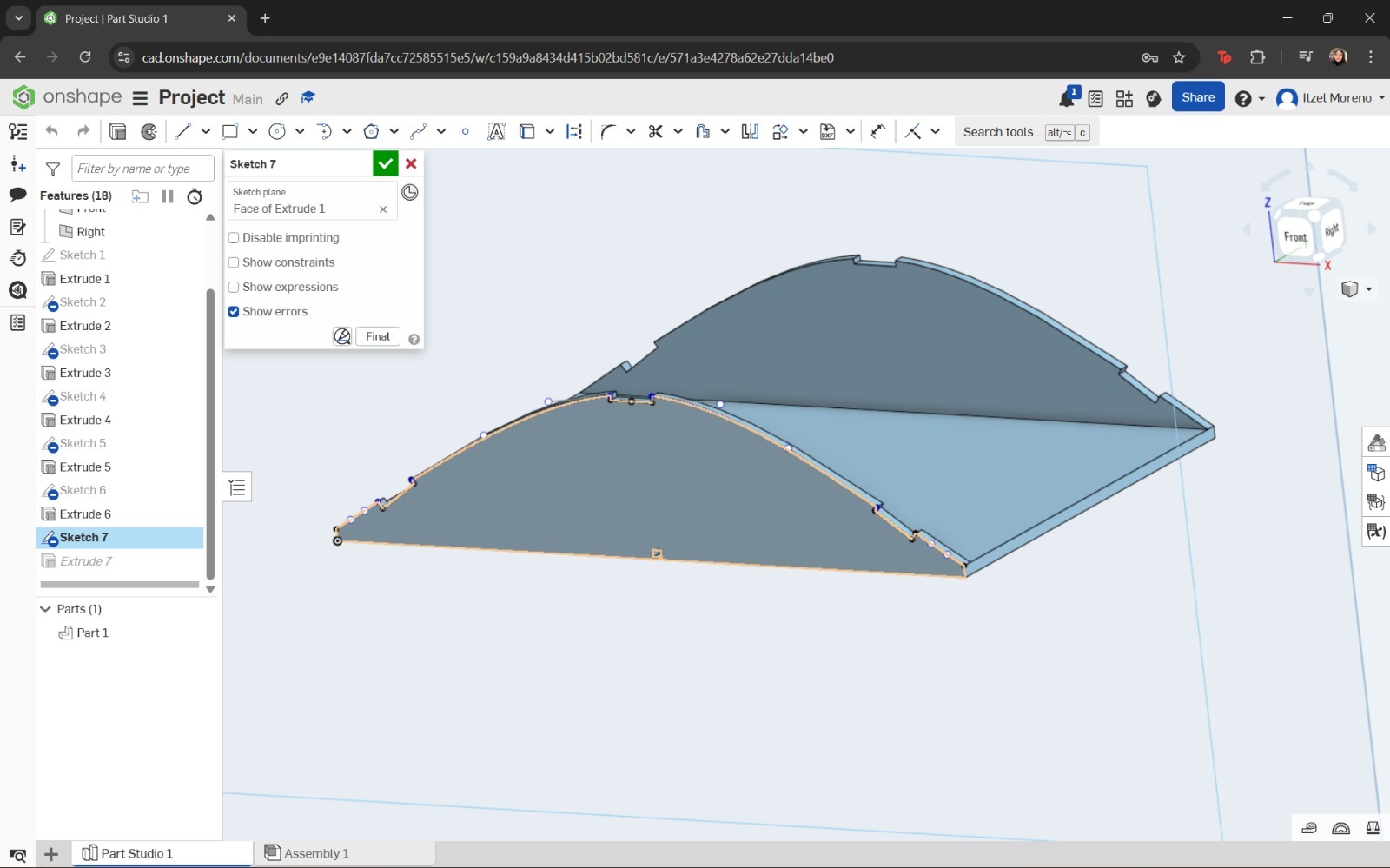
However, instead of using a solid extrusion, the Thin option was selected, and the direction and depth of the cover were configured accordingly.
And that's it
Simulation
For the simulation, I designed a camshaft in SolidWorks. The process I followed was as follows:
And the result of the simulation is shown in the video above.
If you want to access to my work from this week, please click here to download!