Week 16 - Wildcard week
This week's assignment was the ever-changing and varied Wildcard Week! We had to choose a process not covered by any of the previous assignments to explore different avenues offered by everything related to digital fabrication. In my case, I decided to focus this assignment on computer vision by using the robot I have already built and tried to improve upon throughout the Fab Academy.
Work log
Completed tasks
- Demonstrated workflows used in the chosen process.
- Selected and applied suitable processes (and materials) to do the assignment.
1. What did I choose to focus on? Computer Vision!
Computer vision is a subfield of artificial intelligence (AI) that enables machines to interpret visual information from the world, including images, videos, and camera feeds. Just as living beings utilize their eyes and brains to understand their surroundings and take action, computer vision systems employ cameras and algorithms to extract meaningful information from visual inputs.
Integrating a camera into a machine can unlock new functionality, such as:
- Detecting objects in an image, like cars, people, tools, or animals.
- Recognizing faces, gestures or handwritten numbers.
- Tracking movement in a video and detecting behavioral patterns.
- Measuring distance, size, or position using visual data.
- Identifying defects in manufactured parts.
- Helping robots navigate their environment.
Workflow of a Computer Vision System:
- Image acquisition: A camera or sensor captures a frame from the environment.
- Preprocessing: The image is cleaned or adjusted by contrast enhancement and noise reduction routines.
- Feature extraction or Learning: The system identifies key characteristics from the processed image, such as patterns, shapes, colors, edges or textures.
- Decision making: The system's main controller analyzes features and makes decisions or produces outputs based on the extracted features from the image.
2.What did I use for this assignment?
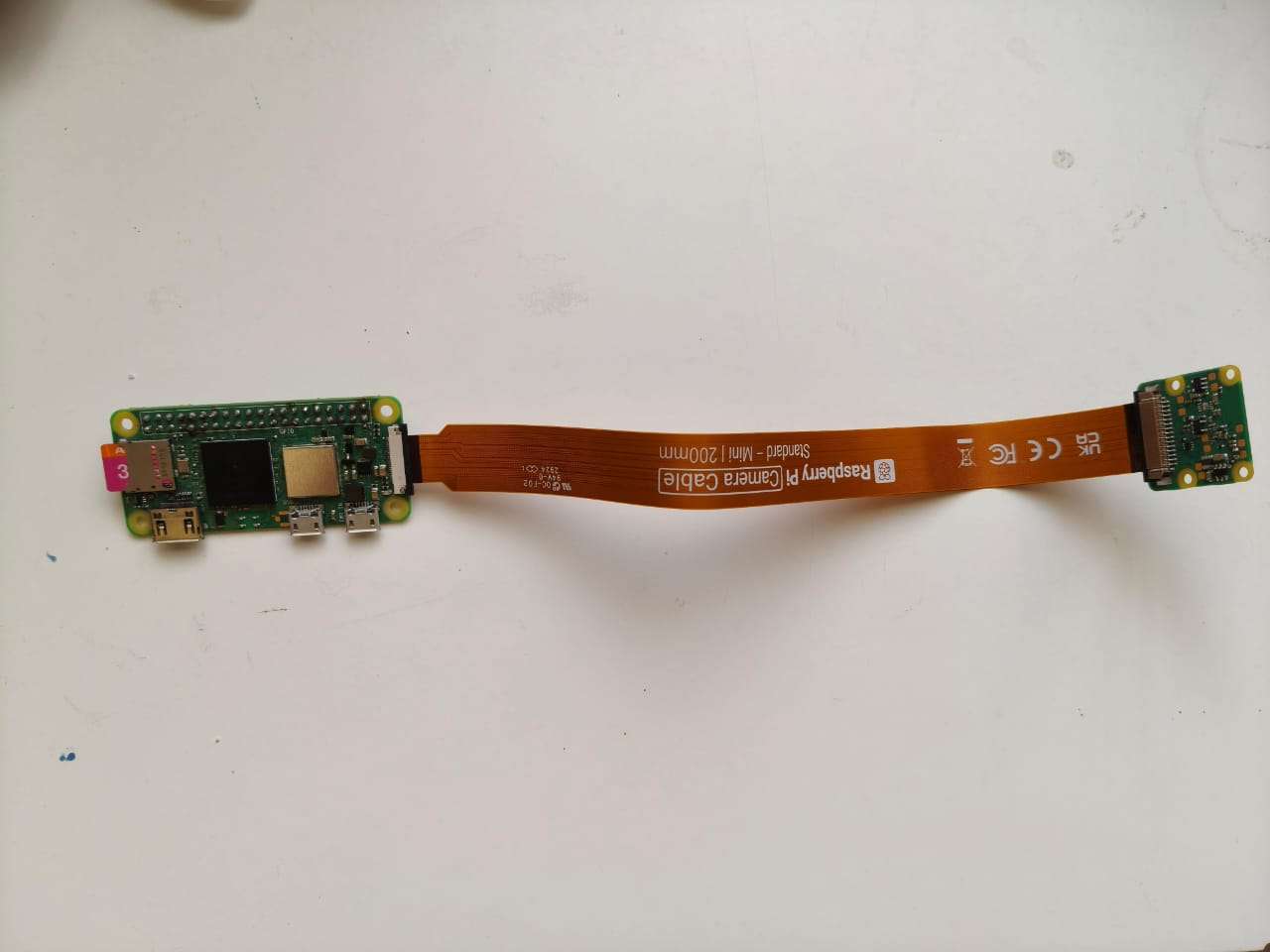
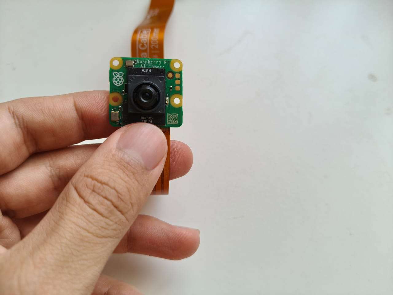
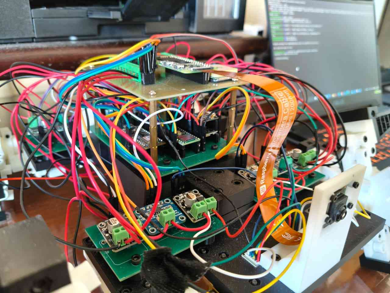
For this week's assignment, I chose to utilize the robot I presented in my master's dissertation project. My robot features a bio-inspired design, incorporating elements abstracted from insects. Its wheel-legs mimic the walking patterns of insects and have been enhanced with fin-ray appendages for improved mobility on rough terrain. The robot's "brain" is a Raspberry Pi Zero 2W single-board computer (SBC), which integrates a quad-core 64-bit ARM Cortex-A53 processor clocked at 1 GHz and 512 MB of LPDDR2 SDRAM. The Pi Zero 2W also serves as the system's "eyes," equipped with a Raspberry Pi AI camera based on Sony's IMX500 Intelligent Vision Sensor. The robot's "muscles" consist of eight DC micrometal gear motors—four for movement and four for transforming the wheel-legs. All motors are driven by DRV8871 circuits, which are managed by a Teensy 4.1 microcontroller. Additional components of the robot include limit switches, a XIAO ESP32-C6 with an L76K GNSS, and an Arduino Nano BLE 33 Sense REV-2; however, these components were not utilized in this week's assignment.
The components used for this assignment included the Raspberry Pi Zero 2W, the Raspberry Pi camera, and the Teensy 4.1, along with its respective motors and drivers for locomotion. The Pi Zero 2W ran its own operating system to execute Python scripts that facilitated the computer vision system workflow. Meanwhile, the Teensy 4.1 was programmed with Arduino code to interpret movement commands from the Pi Zero 2W.
I have primarily used this robot to acquire sensor data and upload it to an online database. The camera provides visual feedback for navigation; however, the robot is not yet autonomous. Therefore, I decided to focus this assignment on enabling the robot to have some level of autonomy, specifically in stopping at a predetermined distance from objects. Since the robot does not have a sensor for measuring distances, I will rely on the camera to determine the distance from the robot to an object.
To implement a routine that transforms the input from the camera into useful information for decision-making, I chose to use OpenCV in the Python code. OpenCV, or Open Source Computer Vision Library, is the preferred library for computer vision tasks. The OpenCV community now maintains the library, which Intel initially developed in 1999. The library is written in C++ and offers official bindings for Python, Java, and other languages. It is optimized for real-time applications and can run on both desktop computers and single-board computers like the Raspberry Pi Zero 2W.
3. Setting up the system
It had been a while since I last used the robot, so I wanted to ensure that the Raspberry Pi would still boot up without any issues. To do this, I decided to detach it from the robot for a closer inspection.
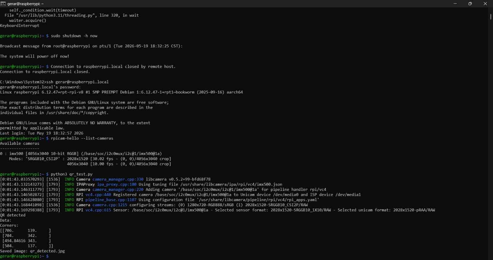
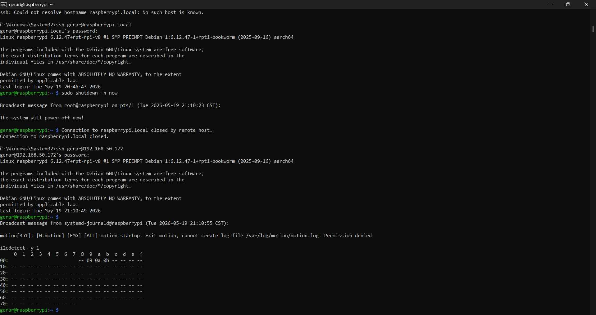
I worked with the Raspberry Pi Zero 2W via SSH, which enables interaction with the board without the need to connect it to a computer or use peripherals like a monitor, mouse, and keyboard. I accessed the board through the Windows Command Prompt by entering ssh your_user@raspberrypi.local, which prompts the Raspberry Pi to request the user's password.
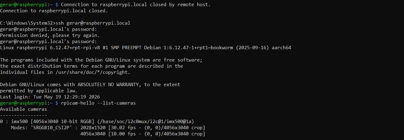
After accessing the Raspberry Pi, I checked that the board could successfully detect the AI camera using the command `rpicam-hello --list-cameras`. The camera was identified as imx500 [4056x3040 10-bit RGB]. Following this, I performed a test capture of an image with the command `rpicam-still -o test.jpg --timeout 2000`. The terminal then began displaying image data until the timeout was reached.
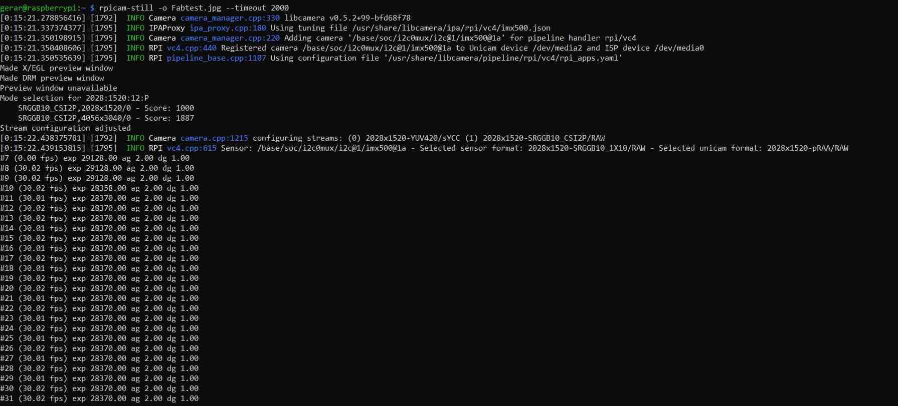
With the timeout expired, I confirmed that an image was indeed captured, which was the case. Now, I could proceed with QR detection. I opted to detect a QR code as a distance reference due to the standardized geometry of QR codes. OpenCV provides easy-to-use and accessible routines for QR detection. Therefore, it would not be difficult to write a code that could measure distance based on the size of the QR code in a frame. So, the next step is to detect QR codes!
To detect QR codes with the hardware I was using, I needed to ensure that I had the proper packages installed, which I did by typing the following commands:
- sudo apt update
- python3 --version
- pip3 --version
- python3 -c "import cv2; print(cv2.__version__)"
- python3 -c "from picamera2 import Picamera2; print('Picamera2 OK')"
- python3 -c "import numpy; print(numpy.__version__)"
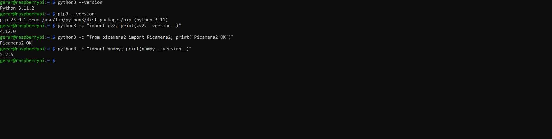
Once I confirmed that the Raspberry Pi has the necessary packages, I mounted it again on the robot for calibration.
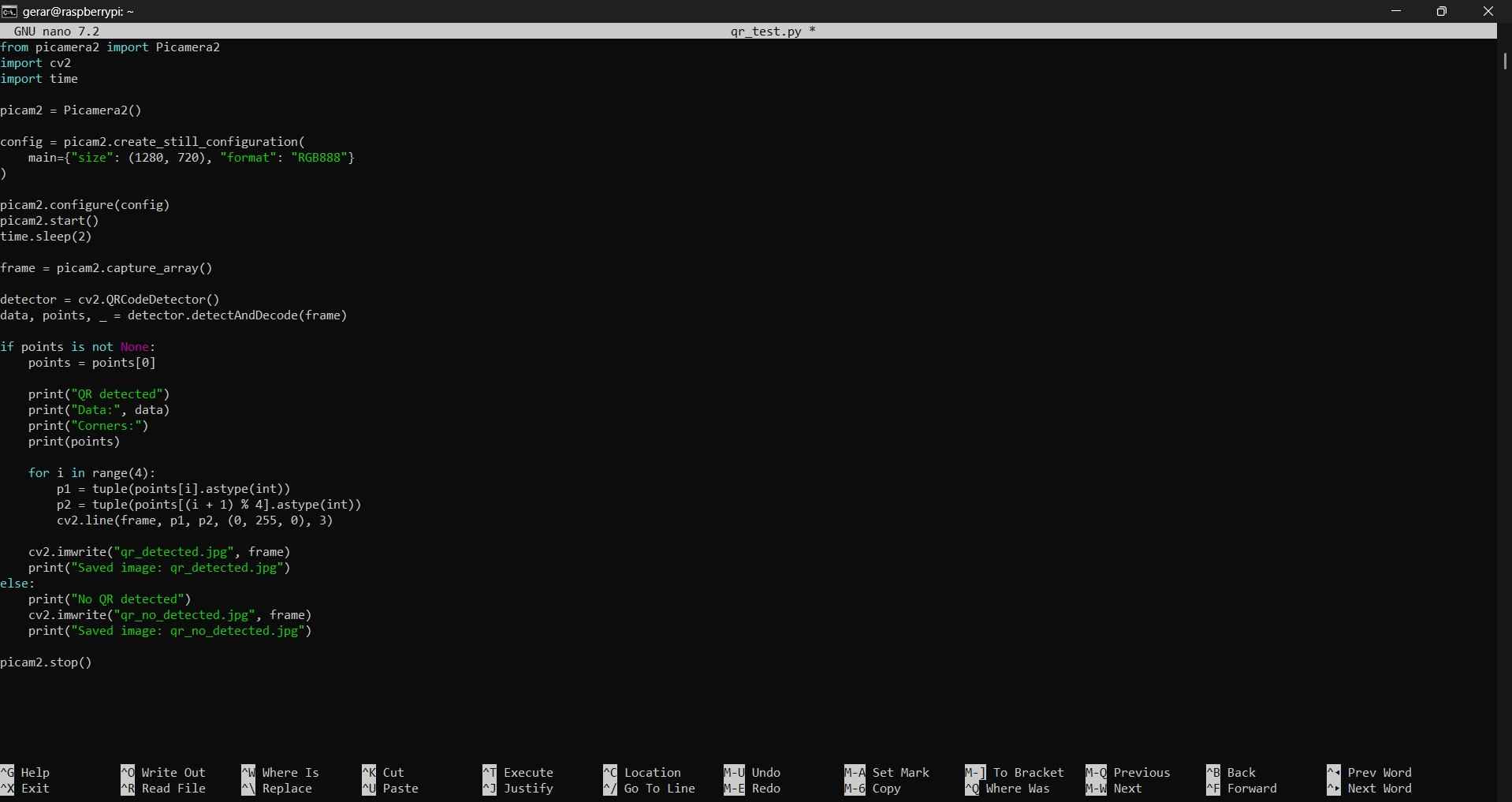
Python code can be uploaded to a Raspberry Pi using two methods: via SSH in Visual Studio Code or through the nano editor, accessible from the same command terminal used to connect to the Raspberry Pi. I chose to use the nano editor. It is worth noting that the code developed for this assignment was created with assistance from ChatGPT. The nano editor can be accessed by typing nano [file_name], which in my case was nano qr_test.py.
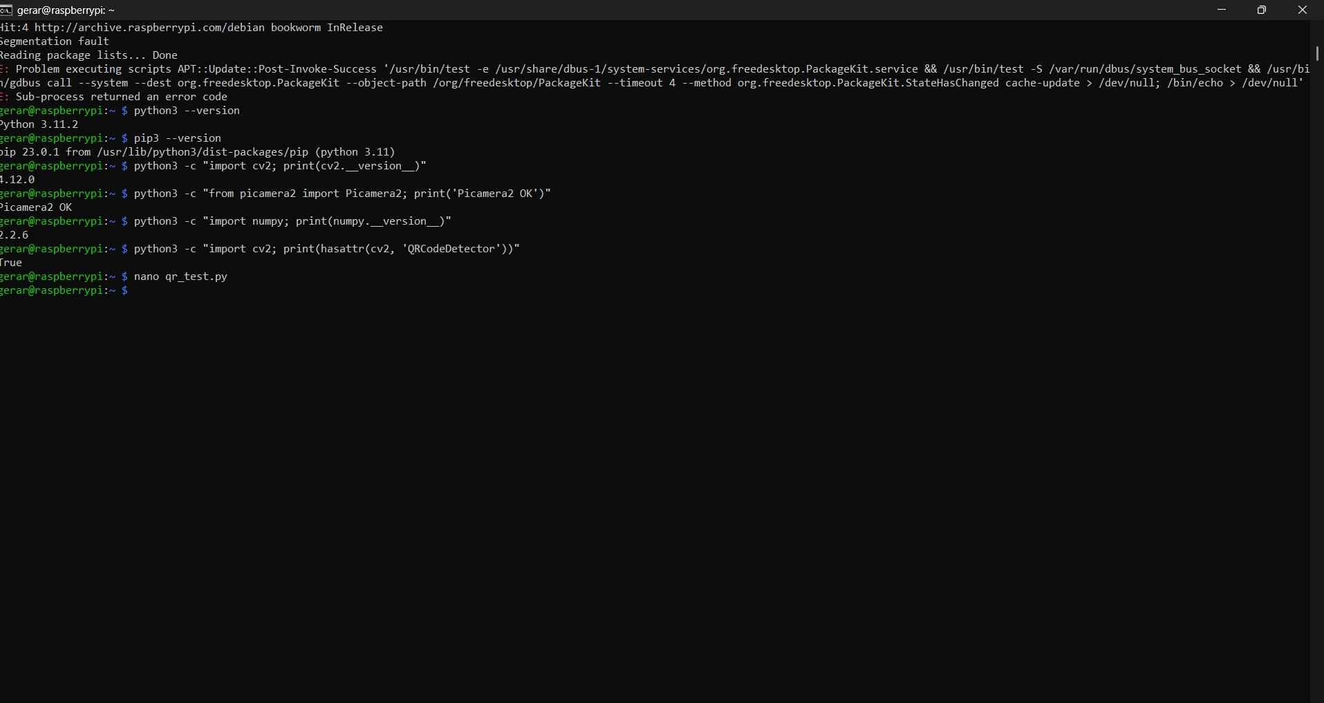
The following code contains the code used for QR detection:
            from picamera2 import Picamera2
            import cv2
            import time

            picam2 = Picamera2()

            config = picam2.create_still_configuration(
                main={"size": (1280, 720), "format": "RGB888"}
            )

            picam2.configure(config)
            picam2.start()
            time.sleep(2)

            frame = picam2.capture_array()

            detector = cv2.QRCodeDetector()
            data, points, _ = detector.detectAndDecode(frame)

            if points is not None:
                points = points[0]

                print("QR detected")
                print("Data:", data)
                print("Corners:")
                print(points)

                for i in range(4):
                    p1 = tuple(points[i].astype(int))
                    p2 = tuple(points[(i + 1) % 4].astype(int))
                    cv2.line(frame, p1, p2, (0, 255, 0), 3)

                cv2.imwrite("qr_detected.jpg", frame)
                print("Saved image: qr_detected.jpg")

            else:
                print("No QR detected")
                cv2.imwrite("qr_no_detected.jpg", frame)
                print("Saved image: qr_no_detected.jpg")

            picam2.stop()
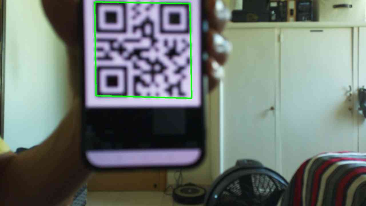
The aim of this sketch is to determine if a QR code can be detected. To achieve this, OpenCV's QRCodeDetector() was used to locate the QR code and extract its four corner points. The script captured an image, identified the QR marker, drew a green bounding box around it, and saved the resulting image. For testing, I displayed a WhatsApp QR code on my phone, which the script successfully detected.
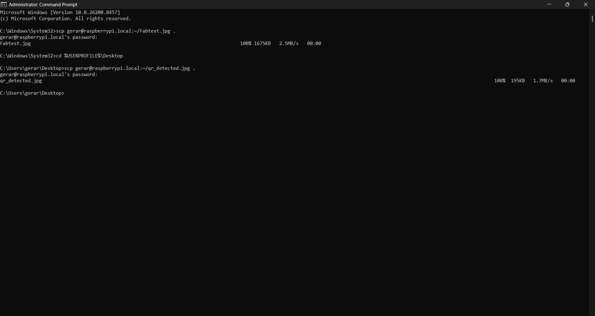
Captured images were transferred from the Raspberry Pi to my computer using a separate CMD terminal, in which I first established the destination folder with cd %USERPROFILE%\Desktop and then established which file I decided to transfer with scp [user]@raspberrypi.local:~/[File name with extension].
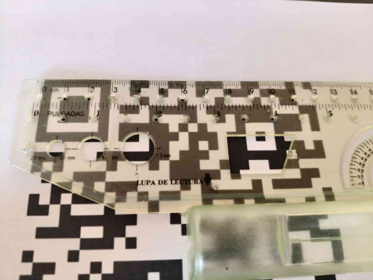
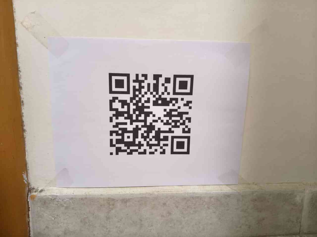
The camera does not directly measure depth. Instead, I chose a monocular vision approach that relies on the apparent size of a known marker. I printed a QR code from Wikipedia, which can be downloaded from that site. The printed QR marker measures 12 cm by 12 cm in real size. I decided to print the marker so that it would have a fixed size and be easier to place on a surface perpendicular to the robot's movement.
4. Calibration
The basic principle for measuring distance with a monocular approach is that when the QR marker is farther away, it appears smaller in pixels, and when the QR marker is closer, it appears larger in pixels. Calibration was necessary to calculate the camera focal length in pixels for the selected image resolution. Once this value was known, the robot could estimate the distance to the QR marker from future images.
The distance was estimated using:
distance_cm = (QR_real_width_cm × focal_px) / QR_width_px
- QR_real_width_cm = real physical width of the printed QR marker
- QR_width_px = detected width of the QR in the image
- focal_px = calibrated focal length in pixels
The focal length in pixels was calculated using a known calibration distance:
focal_px = (QR_width_px × known_distance_cm) / QR_real_width_cm
Python script for calibration:
            from picamera2 import Picamera2
            import cv2
            import time
            import math

            # ── QR calibration setup ──
            # Real physical size of the printed QR marker
            QR_REAL_CM = 12.0

            # Focal length is not known yet during calibration
            FOCAL_PX = None

            # ── Camera setup ──
            picam2 = Picamera2()

            config = picam2.create_still_configuration(
                main={"size": (2028, 1520), "format": "RGB888"}
            )

            picam2.configure(config)
            picam2.start()
            time.sleep(2)

            frame = picam2.capture_array()

            # ── QR detection ──
            detector = cv2.QRCodeDetector()
            data, points, _ = detector.detectAndDecode(frame)

            def distance_between(p1, p2):
                return math.sqrt((p2[0] - p1[0])**2 + (p2[1] - p1[1])**2)

            if points is not None:
                points = points[0]

                # Measure the four sides of the detected QR marker
                side_1 = distance_between(points[0], points[1])
                side_2 = distance_between(points[1], points[2])
                side_3 = distance_between(points[2], points[3])
                side_4 = distance_between(points[3], points[0])

                # Average QR side length in pixels
                qr_width_px = (side_1 + side_2 + side_3 + side_4) / 4

                print("QR detected")
                print("Data:", data)
                print("QR width:", round(qr_width_px, 2), "px")

                print("Calibration mode")
                print("Place the QR marker at a known distance.")
                print("Use this formula:")
                print("FOCAL_PX = (qr_width_px * known_distance_cm) / QR_REAL_CM")

                # Draw QR bounding box
                for i in range(4):
                    p1 = tuple(points[i].astype(int))
                    p2 = tuple(points[(i + 1) % 4].astype(int))
                    cv2.line(frame, p1, p2, (0, 255, 0), 4)

                cv2.imwrite("qr_calibration.jpg", frame)
                print("Saved image: qr_calibration.jpg")

            else:
                print("No QR detected")
                cv2.imwrite("qr_calibration_no_detected.jpg", frame)
                print("Saved image: qr_calibration_no_detected.jpg")

            picam2.stop()
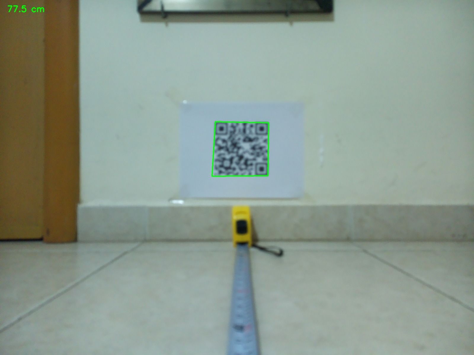
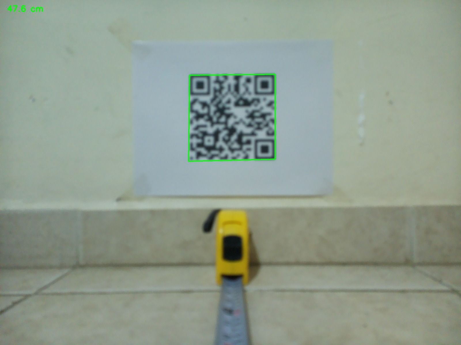
For calibration, the QR marker was placed at a known distance from the camera mounted on the robot. A flexometer was used to measure the distance between the robot and the marker, taking into account the length of the flexometer itself.
The calibrated focal value was estimated using the following parameters:
- Known distance = 782 mm = 78.2 cm
- QR real width = 12.0 cm
- Detected QR width = 229.7 px
Using the formula:
focal_px = (229.7 × 78.2) / 12
The calibrated focal value was approximately 1494.6 px. This value was then used in the final distance estimation script.
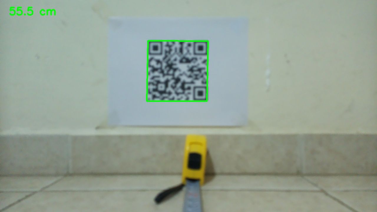
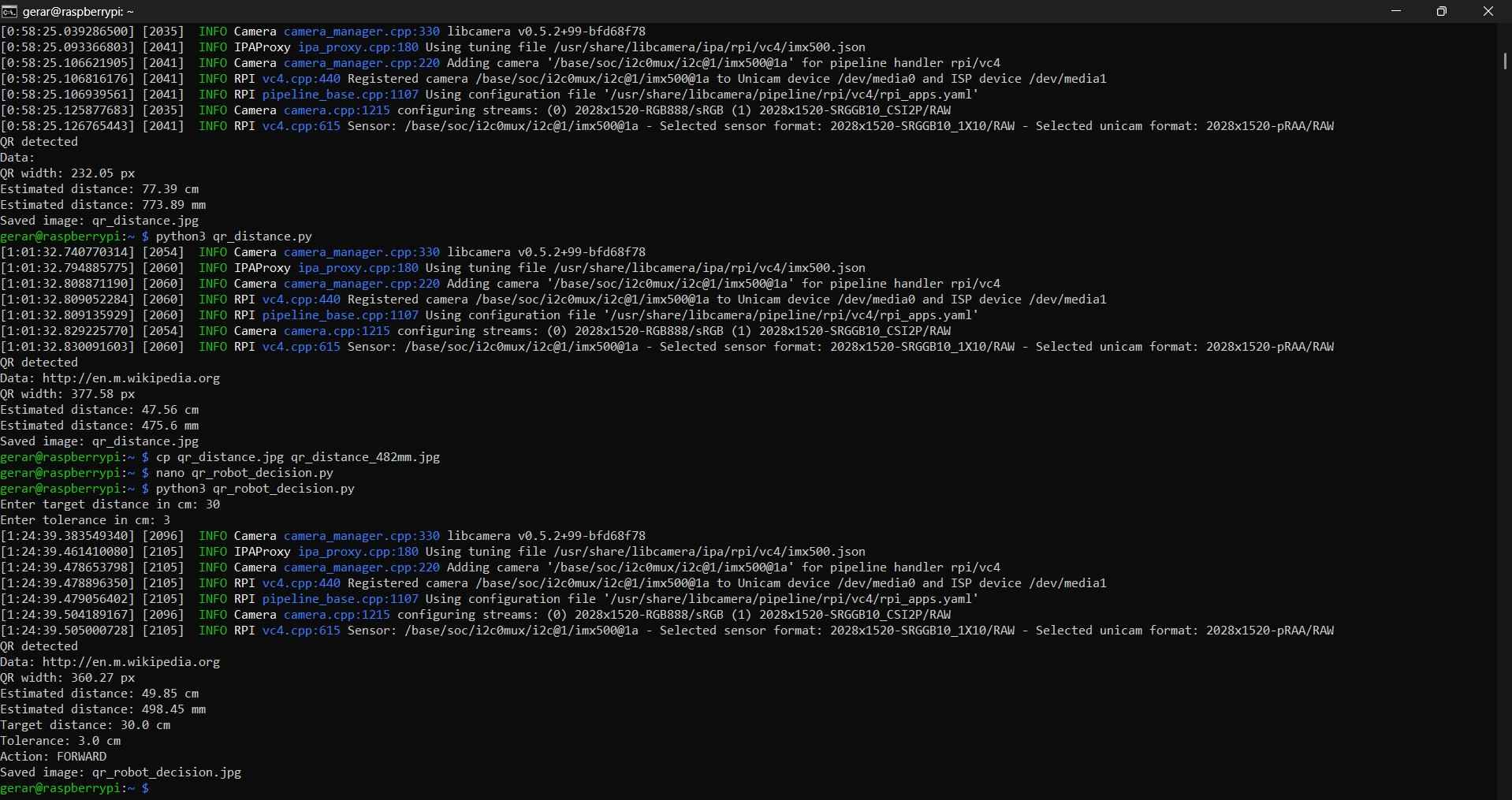
After calibration, I tested the system at three different distances:
| Test | Real distance | Estimated distance | Error |
|---|---|---|---|
| 1 | 552 mm | 554.6 mm | 2.6 mm |
| 2 | 782 mm | 775.0 mm | -7.0 mm |
| 3 | 482 mm | 476.0 mm | -6.0 mm |
The following block shows the python script used for QR detection and distance estimation:
                from picamera2 import Picamera2
                import cv2
                import time
                import math

                # ── QR calibration values ──
                # Real physical size of the printed QR marker
                QR_REAL_CM = 12.0

                # Calibrated focal length in pixels
                # This value was obtained after placing the QR marker at a known distance
                FOCAL_PX = 1496.5

                # ── Camera setup ──
                picam2 = Picamera2()

                config = picam2.create_still_configuration(
                    main={"size": (2028, 1520), "format": "RGB888"}
                )

                picam2.configure(config)
                picam2.start()
                time.sleep(2)

                frame = picam2.capture_array()

                # ── QR detection ──
                detector = cv2.QRCodeDetector()
                data, points, _ = detector.detectAndDecode(frame)

                def distance_between(p1, p2):
                    return math.sqrt((p2[0] - p1[0])**2 + (p2[1] - p1[1])**2)

                if points is not None:
                    points = points[0]

                    # Measure all four sides of the detected QR marker
                    side_1 = distance_between(points[0], points[1])
                    side_2 = distance_between(points[1], points[2])
                    side_3 = distance_between(points[2], points[3])
                    side_4 = distance_between(points[3], points[0])

                    # Average QR side length in pixels
                    qr_width_px = (side_1 + side_2 + side_3 + side_4) / 4

                    # Estimate distance using the calibrated focal length
                    distance_cm = (QR_REAL_CM * FOCAL_PX) / qr_width_px
                    distance_mm = distance_cm * 10

                    print("QR detected")
                    print("Data:", data)
                    print("QR width:", round(qr_width_px, 2), "px")
                    print("Estimated distance:", round(distance_cm, 2), "cm")
                    print("Estimated distance:", round(distance_mm, 2), "mm")

                    # Draw QR bounding box
                    for i in range(4):
                        p1 = tuple(points[i].astype(int))
                        p2 = tuple(points[(i + 1) % 4].astype(int))
                        cv2.line(frame, p1, p2, (0, 255, 0), 4)

                    # Draw estimated distance on the image
                    text = f"{distance_cm:.1f} cm"
                    cv2.putText(frame, text, (30, 70),
                                cv2.FONT_HERSHEY_SIMPLEX, 1.5, (0, 255, 0), 4)

                    cv2.imwrite("qr_distance.jpg", frame)
                    print("Saved image: qr_distance.jpg")

                else:
                    print("No QR detected")
                    cv2.imwrite("qr_no_detected.jpg", frame)
                    print("Saved image: qr_no_detected.jpg")

                picam2.stop()
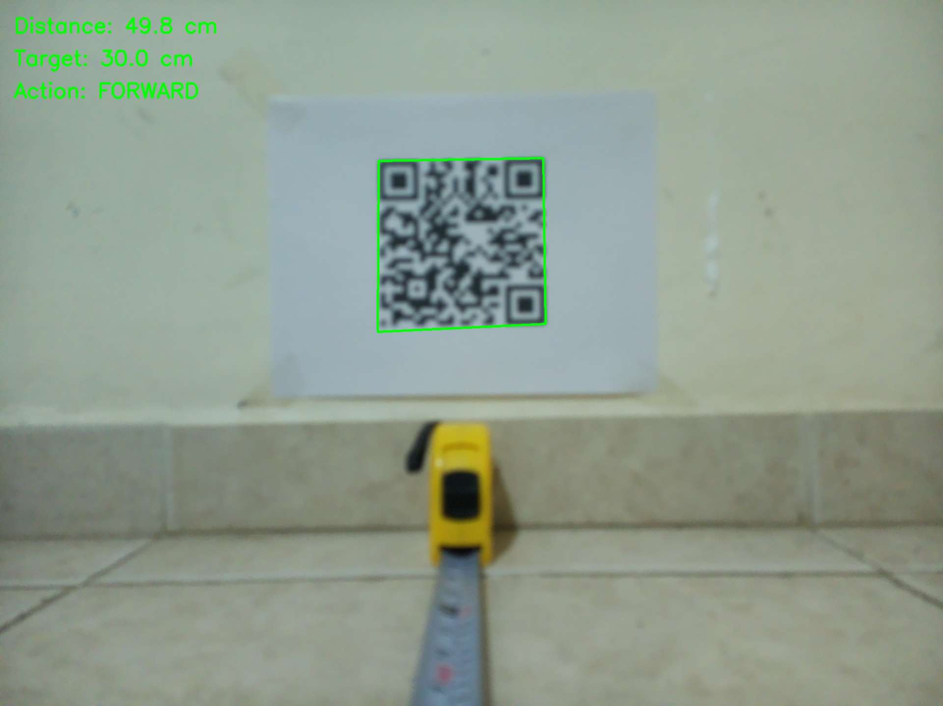
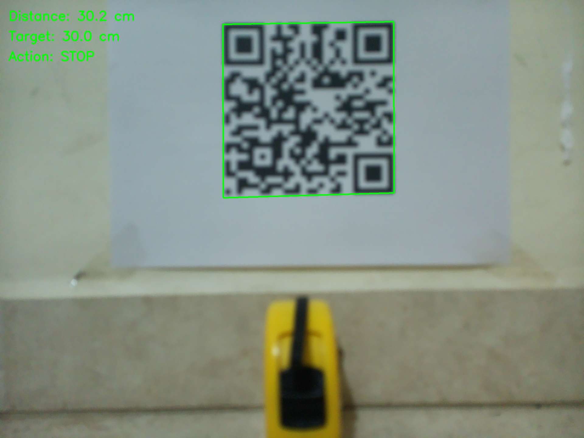
5. Robot decision making
The disparity between the actual and measured distances was only a few millimetres, which I deemed acceptable, considering that the camera is not a dedicated distance sensor and that the focal value can be further refined. At this point, I chose to incorporate a decision layer into my code. This decision layer allows the user to input a target distance and specify a tolerance.
                Target distance = 30 cm
                Tolerance = 3 cm
This would create the following decision logic:
                Distance > 33 cm      → FORWARD
                Distance 27–33 cm     → STOP
                Distance < 27 cm      → TOO CLOSE - STOP
                QR not detected       → QR LOST - STOP
The following block shows the python script used for decision making without actuation:
                from picamera2 import Picamera2
                import cv2
                import time
                import math

                # ── QR calibration values ──
                # Real physical size of the printed QR marker
                QR_REAL_CM = 12.0

                # Calibrated focal length in pixels
                # This value was obtained after calibration at 2028x1520 resolution
                FOCAL_PX = 1496.5

                # ── Ask user for target distance ──
                try:
                    TARGET_CM = float(input("Enter target distance in cm: "))
                    TOLERANCE_CM = float(input("Enter tolerance in cm: "))
                except ValueError:
                    print("Invalid input. Please enter numeric values.")
                    exit()

                # ── Camera setup ──
                picam2 = Picamera2()

                config = picam2.create_still_configuration(
                    main={"size": (2028, 1520), "format": "RGB888"}
                )

                picam2.configure(config)
                picam2.start()
                time.sleep(2)

                frame = picam2.capture_array()

                # ── QR detection ──
                detector = cv2.QRCodeDetector()
                data, points, _ = detector.detectAndDecode(frame)

                def distance_between(p1, p2):
                    return math.sqrt((p2[0] - p1[0])**2 + (p2[1] - p1[1])**2)

                def decide_action(distance_cm):
                    """
                    Safe decision logic:
                    - If the robot is farther than the target range, it should move forward.
                    - If the robot is inside the target range, it should stop.
                    - If the robot is too close, it should stop for safety.
                    """

                    if distance_cm > TARGET_CM + TOLERANCE_CM:
                        return "FORWARD"
                    elif distance_cm < TARGET_CM - TOLERANCE_CM:
                        return "TOO CLOSE - STOP"
                    else:
                        return "STOP"

                if points is not None:
                    points = points[0]

                    # Measure all four sides of the detected QR marker
                    side_1 = distance_between(points[0], points[1])
                    side_2 = distance_between(points[1], points[2])
                    side_3 = distance_between(points[2], points[3])
                    side_4 = distance_between(points[3], points[0])

                    # Average QR side length in pixels
                    qr_width_px = (side_1 + side_2 + side_3 + side_4) / 4

                    # Estimate distance using calibrated focal length
                    distance_cm = (QR_REAL_CM * FOCAL_PX) / qr_width_px
                    distance_mm = distance_cm * 10

                    # Select action based on estimated distance
                    action = decide_action(distance_cm)

                    print("QR detected")
                    print("Data:", data)
                    print("QR width:", round(qr_width_px, 2), "px")
                    print("Estimated distance:", round(distance_cm, 2), "cm")
                    print("Estimated distance:", round(distance_mm, 2), "mm")
                    print("Target distance:", TARGET_CM, "cm")
                    print("Tolerance:", TOLERANCE_CM, "cm")
                    print("Action:", action)

                    # Draw QR bounding box
                    for i in range(4):
                        p1 = tuple(points[i].astype(int))
                        p2 = tuple(points[(i + 1) % 4].astype(int))
                        cv2.line(frame, p1, p2, (0, 255, 0), 4)

                    # Draw information on the image
                    cv2.putText(frame, f"Distance: {distance_cm:.1f} cm", (30, 70),
                                cv2.FONT_HERSHEY_SIMPLEX, 1.5, (0, 255, 0), 4)

                    cv2.putText(frame, f"Target: {TARGET_CM:.1f} cm", (30, 140),
                                cv2.FONT_HERSHEY_SIMPLEX, 1.5, (0, 255, 0), 4)

                    cv2.putText(frame, f"Action: {action}", (30, 210),
                                cv2.FONT_HERSHEY_SIMPLEX, 1.5, (0, 255, 0), 4)

                    cv2.imwrite("qr_robot_decision.jpg", frame)
                    print("Saved image: qr_robot_decision.jpg")

                else:
                    action = "QR LOST - STOP"

                    print("No QR detected")
                    print("Action:", action)

                    cv2.putText(frame, action, (30, 70),
                                cv2.FONT_HERSHEY_SIMPLEX, 1.5, (0, 0, 255), 4)

                    cv2.imwrite("qr_robot_decision_lost.jpg", frame)
                    print("Saved image: qr_robot_decision_lost.jpg")

                picam2.stop()
After confirming that the script could accurately determine when to stop and move forward, I decided to connect it to the robot's actuators. As I mentioned earlier, I hadn't worked on the robot for some time, so the code I had used for testing the motors was still available. This code allowed the Teensy 4.1 (0x09) to receive commands from the Pi Zero via I2C. I checked if the Pi Zero 2W could still "talk" to the Teensy 4.1, so I used the i2c scanner with the command line: i2cdetect -y 1. The three microcontrollers, including the Teensy 4.1, appeared in the I2C bus, so it was safe to proceed.
Python script
The Python script served as the main control program on the Raspberry Pi Zero 2W. Its purpose was to process images captured by the Raspberry Pi AI Camera to detect the QR marker, estimate the distance to it, and send movement commands to the Teensy 4.1 via I2C.
                from picamera2 import Picamera2
                import cv2
                import time
                import math
                from smbus2 import SMBus

                # ── I2C / Teensy setup ──
                I2C_BUS = 1
                TEENSY_ADDR = 0x09

                # ── Command bytes used by the Teensy target ──
                CMD_ALL_FWD = 0x01
                CMD_ALL_BACK = 0x02
                CMD_ALL_COAST = 0x03
                CMD_ALL_BRAKE = 0x04
                CMD_SET_SPEED_DR = 0x10

                # ── Movement tuning ──
                DRIVE_SPEED = 190      # PWM speed, 0-255
                PULSE_TIME = 0.25      # seconds moving forward per step
                STOP_TIME = 0.7        # pause after each movement pulse
                MAX_STEPS = 20         # safety limit

                # ── QR calibration ──
                QR_REAL_CM = 12.0
                FOCAL_PX = 1496.5      # calibrated for 2028x1520 capture resolution

                # ── Ask user for target distance ──
                try:
                    TARGET_CM = float(input("Enter target distance in cm: "))
                    TOLERANCE_CM = float(input("Enter tolerance in cm: "))
                except ValueError:
                    print("Invalid input. Please enter numeric values.")
                    exit()

                # ── I2C motor functions ──
                bus = SMBus(I2C_BUS)

                def set_drive_speed(speed):
                    speed = max(0, min(255, int(speed)))
                    bus.write_byte_data(TEENSY_ADDR, CMD_SET_SPEED_DR, speed)

                def robot_forward():
                    bus.write_byte(TEENSY_ADDR, CMD_ALL_FWD)

                def robot_coast():
                    bus.write_byte(TEENSY_ADDR, CMD_ALL_COAST)

                def safe_stop():
                    """
                    Stop the robot using COAST only.
                    During testing, using BRAKE caused occasional I2C errors,
                    probably due to electrical noise or sudden motor current changes.
                    """
                    try:
                        robot_coast()
                        time.sleep(0.2)
                    except OSError as e:
                        print("I2C error while stopping:", e)

                # ── Camera setup ──
                picam2 = Picamera2()

                config = picam2.create_still_configuration(
                    main={"size": (2028, 1520), "format": "RGB888"}
                )

                picam2.configure(config)
                picam2.start()
                time.sleep(2)

                detector = cv2.QRCodeDetector()

                def distance_between(p1, p2):
                    return math.sqrt((p2[0] - p1[0])**2 + (p2[1] - p1[1])**2)

                def detect_qr_distance(frame):
                    data, points, _ = detector.detectAndDecode(frame)

                    if points is None:
                        return None, None, None

                    points = points[0]

                    side_1 = distance_between(points[0], points[1])
                    side_2 = distance_between(points[1], points[2])
                    side_3 = distance_between(points[2], points[3])
                    side_4 = distance_between(points[3], points[0])

                    qr_width_px = (side_1 + side_2 + side_3 + side_4) / 4
                    distance_cm = (QR_REAL_CM * FOCAL_PX) / qr_width_px

                    return data, points, distance_cm

                def draw_result(frame, points, distance_cm, action, step):
                    if points is not None:
                        for i in range(4):
                            p1 = tuple(points[i].astype(int))
                            p2 = tuple(points[(i + 1) % 4].astype(int))
                            cv2.line(frame, p1, p2, (0, 255, 0), 4)

                    cv2.putText(frame, f"Distance: {distance_cm:.1f} cm", (30, 70),
                                cv2.FONT_HERSHEY_SIMPLEX, 1.5, (0, 255, 0), 4)

                    cv2.putText(frame, f"Target: {TARGET_CM:.1f} cm", (30, 140),
                                cv2.FONT_HERSHEY_SIMPLEX, 1.5, (0, 255, 0), 4)

                    cv2.putText(frame, f"Action: {action}", (30, 210),
                                cv2.FONT_HERSHEY_SIMPLEX, 1.5, (0, 255, 0), 4)

                    cv2.putText(frame, f"Step: {step}", (30, 280),
                                cv2.FONT_HERSHEY_SIMPLEX, 1.5, (0, 255, 0), 4)

                # ── Main control loop ──
                print("Starting QR visual approach")
                print("Target:", TARGET_CM, "cm")
                print("Tolerance:", TOLERANCE_CM, "cm")
                print("Drive speed:", DRIVE_SPEED)
                print("Pulse time:", PULSE_TIME, "s")
                print("Press Ctrl+C to stop manually")

                set_drive_speed(DRIVE_SPEED)
                safe_stop()

                try:
                    for step in range(1, MAX_STEPS + 1):
                        print("-----------------------")
                        print("Step:", step)

                        frame = picam2.capture_array()
                        data, points, distance_cm = detect_qr_distance(frame)

                        if distance_cm is None:
                            action = "QR LOST - STOP"
                            print(action)
                            safe_stop()

                            cv2.putText(frame, action, (30, 70),
                                        cv2.FONT_HERSHEY_SIMPLEX, 1.5, (0, 0, 255), 4)

                            cv2.imwrite("qr_robot_move_lost.jpg", frame)
                            break

                        distance_mm = distance_cm * 10

                        print("QR detected")
                        print("Data:", data)
                        print("Distance:", round(distance_cm, 2), "cm")
                        print("Distance:", round(distance_mm, 2), "mm")

                        if distance_cm > TARGET_CM + TOLERANCE_CM:
                            action = "FORWARD PULSE"
                            print("Action:", action)

                            draw_result(frame, points, distance_cm, action, step)
                            cv2.imwrite("qr_robot_move.jpg", frame)

                            robot_forward()
                            time.sleep(PULSE_TIME)
                            safe_stop()
                            time.sleep(STOP_TIME)

                        else:
                            action = "TARGET REACHED - STOP"
                            print("Action:", action)

                            safe_stop()
                            draw_result(frame, points, distance_cm, action, step)
                            cv2.imwrite("qr_robot_move.jpg", frame)

                            print("Robot stopped at target range.")
                            break

                    else:
                        print("Maximum number of steps reached. Stopping robot.")
                        safe_stop()

                except KeyboardInterrupt:
                    print("Interrupted by user.")
                    safe_stop()

                finally:
                    safe_stop()
                    picam2.stop()
                    bus.close()
                    print("Finished safely.")
Table 1. Python libraries
| Library | Use |
|---|---|
| Picamera2 | Enables the use of the Raspberry Pi AI Camera and captures images. |
| cv2 | Open CV library, provides functions for QR markers, draws the bounding box, and writes output images. |
| time | Adds delays for camera warm-up, motor pulses, and stop pauses |
| math | Used for calculating the distance between QR corner points. |
| SMBus | Enables I2C communication to send commands from the Raspberry Pi controller to the Teensy target. |
Table 2. Python key variables
| Variable | Value stored | Function |
|---|---|---|
| I2C_BUS | 1 | Raspberry Pi I2C bus number |
| TEENSY_ADDR | 0x09 | Teensy I2C target address |
| DRIVE_SPEED | 190 | PWM speed value for the motors |
| PULSE_TIME | 0.25 s | Duration of each forward movement pulse |
| STOP_TIME | 0.7 s | Pause after each movement pulse before measuring again |
| MAX_STEPS | 20 | Maximum number of steps to avoid infinite movement |
| QR_REAL_CM | 12 | Real physical width of the printed QR marker (CM) |
| FOCAL_PX | 1496.5 | Calibrated focal length in pixels |
| TARGET_CM | User input | Desired stopping distance (CM) |
| TOLERANCE_CM | User input | Accepted distance range around the target (CM) |
Table 3. Python I2C command bytes
| Command variable | Byte | Function |
|---|---|---|
| CMD_ALL_FWD | 0x01 | Move all drive motors forward |
| CMD_ALL_BCK | 0x02 | Move all drive motors backward, defined but not used in final QR test |
| CMD_ALL_COAST | 0x03 | Coast/stop all drive motors |
| CMD_ALL_BRAKE | 0x04 | Brake all motors, defined but avoided in final test |
| CMD_SET_SPEED_DR | 0x10 | Set the speed of the drive motors |
Table 4. Python function overview
| Function | What it does |
|---|---|
| set_drive_speed(speed) | Sends the PWM speed value to the Teensy using I2C command 0x10 |
| robot_forward() | Sends command 0x01 to move all drive motors forward |
| robot_coast() | Sends command 0x03 to stop the motors by coasting |
| safe_stop() | Stops the robot using coast and catches possible I2C errors |
| distance_between(p1, p2) | Calculates the pixel distance between two QR corner points |
| detect_qr_distance(frame) | Detects QR codes in the frame and calculates the distance to the target |
| draw_result(frame, points, distance_cm, action, step) | Draws the QR box, distance, target, action, and step number on the output image |
Table 5. Movement logic
| Condition | Action |
|---|---|
| QR not detected | QR LOST - STOP |
| distance_cm > TARGET_CM + TOLERANCE_CM | Move forward for one short pulse |
| distance_cm <= TARGET_CM + TOLERANCE_CM | Stop because the robot reached the target distance |
| Maximum number of steps reached | Stop for safety |
| User presses Ctrl + C | Stop for safety |
Table 6. Pulse adjustments
| Parameter | Initial behavior | Adjustment |
|---|---|---|
| Movement style | Robot moved too much after a forward command | Movement was changed to short pulses |
| PULSE_TIME | Longer pulse caused overshoot | Reduced to 0.25 s |
| STOP_TIME | Shorter pause between actions | Increased to 0.7 s to allow the robot to stabilize |
| Brake behavior | Brake caused occasional I2C errors | Switched to coasting for safer stopping |
Arduino Code
The Teensy 4.1 code, written in Arduino, configures the Teensy 4.1 as a low-level motor controller. It does not handle camera data. Instead, it awaits I2C commands from the Raspberry Pi and translates those commands into PWM signals for the motor drivers.
            #include <Arduino.h>
            #include <Wire.h>

            // ─────────────────────────────────────────────
            // Teensy 4.1 ↔ Raspberry Pi I2C communication
            // ─────────────────────────────────────────────
            //
            // Updated I2C terminology:
            // - Controller: the device that starts the I2C transaction.
            // - Target: the device that responds to the controller.
            //
            // In this setup:
            // - Raspberry Pi Zero 2 W = I2C controller
            // - Teensy 4.1 = I2C target at address 0x09
            //
            // Teensy 4.1 I2C2 pins:
            // - SDA2 = pin 25
            // - SCL2 = pin 24

            TwoWire &I2CS = Wire2;      // I2C2 target interface

            // Drive motor pins, DRV8871 motor drivers

            const int PIN_IN1 = 28, PIN_IN2 = 29;  // Motor 1
            const int PIN_IN3 = 37, PIN_IN4 = 36;  // Motor 2
            const int PIN_IN5 = 23, PIN_IN6 = 22;  // Motor 3
            const int PIN_IN7 = 0,  PIN_IN8 = 1;   // Motor 4

            // Motor mapping

            struct DriveMotor {
            const int IN1;
            const int IN2;
            };

            DriveMotor motors[4] = {
            {PIN_IN1, PIN_IN2},
            {PIN_IN3, PIN_IN4},
            {PIN_IN5, PIN_IN6},
            {PIN_IN7, PIN_IN8},
            };

            const uint8_t N_MOTORS = 4;

            // PWM setup

            const uint32_t PWM_FREQ = 25000;  // 25 kHz
            const uint8_t  PWM_RES  = 8;      // 8-bit PWM, 0-255

            uint8_t speed_drive = 199;        // Default drive speed, 0-255

            // Motor actions

            #define M_COAST 0
            #define M_FWD   1
            #define M_BACK  2
            #define M_BRAKE 3

            void motor_cmd(int idx, uint8_t action, uint8_t speed) {
            const auto &m = motors[idx];

            switch (action) {
                case M_FWD:
                analogWrite(m.IN1, speed);
                analogWrite(m.IN2, 0);
                break;

                case M_BACK:
                analogWrite(m.IN1, 0);
                analogWrite(m.IN2, speed);
                break;

                case M_COAST:
                analogWrite(m.IN1, 0);
                analogWrite(m.IN2, 0);
                break;

                case M_BRAKE:
                analogWrite(m.IN1, speed);
                analogWrite(m.IN2, speed);
                break;
            }
            }

            void drive_all(uint8_t action, uint8_t speed) {
            for (int i = 0; i < N_MOTORS; i++) {
                motor_cmd(i, action, speed);
            }
            }

            // I2C target interface for Raspberry Pi

            #define I2C_ADDR 0x09

            // Command bytes received from the Raspberry Pi controller
            #define CMD_ALL_FWD        0x01   // Move all drive motors forward
            #define CMD_ALL_BACK       0x02   // Move all drive motors backward
            #define CMD_ALL_COAST      0x03   // Coast all drive motors
            #define CMD_ALL_BRAKE      0x04   // Brake all drive motors
            #define CMD_SET_SPEED_DR   0x10   // Set drive speed: [speed]

            // This function runs whenever the Raspberry Pi sends data to the Teensy target.
            void onReceiveI2C(int len) {
            if (len <= 0) return;

            uint8_t cmd = I2CS.read();

            switch (cmd) {
                case CMD_ALL_FWD:
                drive_all(M_FWD, speed_drive);
                break;

                case CMD_ALL_BACK:
                drive_all(M_BACK, speed_drive);
                break;

                case CMD_ALL_COAST:
                drive_all(M_COAST, 0);
                break;

                case CMD_ALL_BRAKE:
                drive_all(M_BRAKE, speed_drive);
                break;

                case CMD_SET_SPEED_DR:
                if (I2CS.available() >= 1) {
                    speed_drive = I2CS.read();
                }
                break;

                default:
                break;
            }
            }

            // Setup


            void setup() {
            Serial.begin(115200);

            // Start the I2C target interface.
            I2CS.begin(I2C_ADDR);
            I2CS.onReceive(onReceiveI2C);

            // Configure PWM resolution.
            analogWriteResolution(PWM_RES);

            // Configure motor pins.
            for (uint8_t i = 0; i < N_MOTORS; i++) {
                pinMode(motors[i].IN1, OUTPUT);
                pinMode(motors[i].IN2, OUTPUT);

                analogWriteFrequency(motors[i].IN1, PWM_FREQ);
                analogWriteFrequency(motors[i].IN2, PWM_FREQ);
            }

            // Start with all motors stopped.
            drive_all(M_COAST, 0);

            Serial.println("Teensy ready as I2C target @0x09 using Wire2: SDA2=25, SCL2=24.");
            }


            // Loop

            void loop() {
            // Nothing is required here for the QR movement test.
            // The motors are controlled through I2C receive events.
            }
Table 7. Teensy 4.1 pin definitions
| Pin group | Pins | Role |
|---|---|---|
| Motor 1 | PIN_IN1 = 28, PIN_IN2 = 29 | DRV8871 control pins for drive motor 1 |
| Motor 2 | PIN_IN3 = 37, PIN_IN4 = 36 | DRV8871 control pins for drive motor 2 |
| Motor 3 | PIN_IN5 = 23, PIN_IN6 = 22 | DRV8871 control pins for drive motor 3 |
| Motor 4 | PIN_IN7 = 0, PIN_IN8 = 1 | DRV8871 control pins for drive motor 4 |
| I2C2 SDA | 25 | SDA line for Teensy as I2C target |
| I2C2 SCL | 24 | SCL line for Teensy as I2C target |
Table 8. Teensy 4.1 key variables
| I2CS | Wire2 | I2C interface used by the Teensy as target for the Raspberry Pi |
|---|---|---|
| I2C_ADDR | 0x09 | Teensy I2C target address |
| PWM_FREQ | 25000 | PWM frequency for the motor drivers |
| PWM_RES | 8 | PWM resolution, giving values from 0 to 255 |
| Motor 4 | PIN_IN7 = 0, PIN_IN8 = 1 | DRV8871 control pins for drive motor 4 |
| speed_drive | Default 199, updated by Pi | Drive speed variable |
| N_MOT | 4 | Number of motors |
Table 9. Teensy 4.1 Motor actions
| Action constant | Value | Description |
|---|---|---|
| M_COAST | 0 | Moves the motor forward |
| M_FWD | 1 | Moves the motor forward |
| M_BACK | 2 | Moves the motor backward |
| M_BRAKE | 3 | Brakes the motor by applying PWM to both inputs |
Table 10. Teensy 4.1 I2C command bytes
| Command | Byte | What it does |
|---|---|---|
| CMD_ALL_FWD | 0x01 | Moves all drive motors forward using speed_drive |
| CMD_ALL_BACK | 0x02 | Moves all drive motors backward using speed_drive |
| CMD_ALL_COAST | 0x03 | Stops all drive motors using coast |
| CMD_ALL_BRAKE | 0x04 | Brakes all drive motors by applying PWM to both inputs |
| CMD_SET_SPEED_DR | 0x10 | Updates speed_drive with a value from 0 to 255 |
| CMD_PER_MOTOR | 0x30 | Allows individual motor control, but was not used in the QR movement test |
Table 11. Teensy 4.1 function overview
| Function | Description |
|---|---|
| motor_cmd(idx, action, vel) | Controls one motor using its index, action, and PWM value |
| drive_all(action, vel) | Applies the same motor action to all four drive motors |
| onReceiveI2C(len) | Runs when the Raspberry Pi sends an I2C command to the Teensy |
| setup() | Initializes I2C target mode, motor pins, PWM, sensors, and starts with motors stopped |
| loop() | Updates sensors and telemetry in the full code; not directly needed for the QR movement test |
Table 12. Raspberry Pi To Teensy communication
| Python line/ action | Teensy receives | Teensy response |
|---|---|---|
| bus.write_byte_data(TEENSY_ADDR, CMD_SET_SPEED_DR, speed) | 0x10 [speed] | Updates speed_drive |
| bus.write_byte(TEENSY_ADDR, CMD_ALL_FWD) | 0x01 | Calls drive_all(M_FWD, speed_drive) |
| bus.write_byte(TEENSY_ADDR, CMD_ALL_COAST) | 0x03 | Calls drive_all(M_COAST, 0) |
| TEENSY_ADDR = 0x09 | Matches I2C_ADDR = 0x09 | Allows the Raspberry Pi to address the Teensy target |
6. Testing
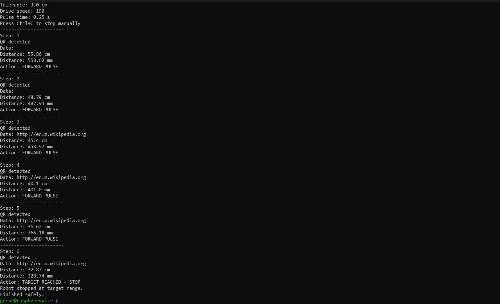
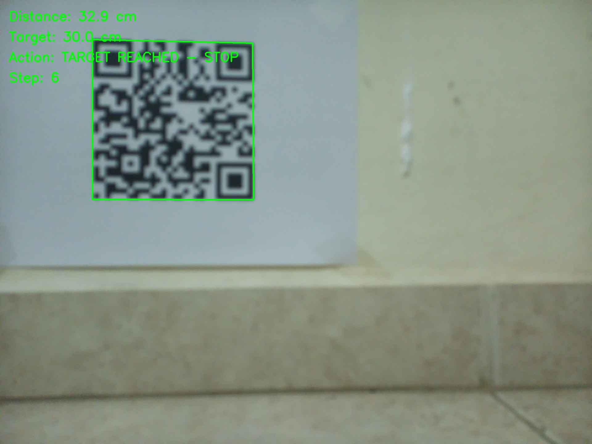
With the codes written and the robot powered up, it was time to test whether the entire system could advance to a specified distance from the marker and remain there. As noted in the code tables, adjustments were made to the robot's movement pulse durations to prevent overshooting the target. Coasting was selected instead of braking to stop the motors; this decision was made because shorting the drivers to halt the motors generated a current surge that disrupted the I2C connection. The system was configured to achieve a distance of 30 cm from the marker, with a tolerance of 3 cm.
Video demonstration
The following video demonstrates the functionality of the overall system:
Files
Here are the downloadable files for this week:
Sources codes for this weekReflection
If I recall correctly, this is the first time I have used OpenCV as part of the decision-making process in a physical system. I hope to deepen my understanding of this library, which I have only previously utilized for processing and storing images. One important lesson I learned during this assignment is that I2C resistors should always be included, even though the microcontrollers I used already have internal resistors for that communication protocol. This is because internal resistors often have values in the range of tens of thousands of ohms, making them susceptible to electronic noise generated by actions such as motor braking. I will make sure to incorporate a proper I2C bus in my final project robot.