Week 05: 3D Scanning and Printing
This week we were introduced to additive manufacturing, better known as 3D printing, a technique that builds objects layer by layer instead of removing material from a block. We also learned about 3D scanning, which captures the shape of real-world objects and converts them into digital models, which can later be additively manufactured. The first task for this week's assignment was to design and 3D print an object that could not be made subtractively. The second task was to 3D scan an object. The design rules for the 3D printers available at the FabLab were tested for this week's group assignment.
Work log
Completed tasks
- Designed an object that could not be made subtractively
- 3D printed the object
- 3D scanned an object
1.What is 3D Printing?
3D printing is a manufacturing technique in which the shape of an object is built layer by layer. Unlike subtractive manufacturing techniques, like laser cutting or machining, which remove material to create an object, 3D printing adds material in thin horizontal layers that are stacked on top of one another to achieve the desired form.
Common additive manufacturing techniques include:
- Fused Deposition Modeling (FDM): In this technique, a spool of thermoplastic filament is fed through a heated nozzle that melts the material and monolithically deposits it layer by layer to build an object. Common materials for this technique include PLA, ABS, PETG, TPU, or nylon.
- Stereolithography (SLA): This technique uses a UV laser to cure liquid photopolymer resin in the layers of an object. Photopolymers used in this technique are available on the market in standard, tough, flexible, castable, high-temperature, and biocompatible variants.
- Continuous Liquid Interface Production (CLIP): This resin process uses an oxygen-permeable window to create a "dead zone" where resin doesn't cure, allowing for continuous printing rather than discrete layers. This process delivers geometries faster than traditional SLA printing. Photopolymers for this process include elastomers, rigid urethanes, and high-temperature variants.
- Powder Bed Fusion (PBF): This technique uses a high-powered laser or electron beam to selectively melt and fuse powdered metallic materials in a bed layer by layer. Common materials include metals like stainless steel, aluminum, and titanium, as well as polymers like nylon and polycarbonate.
- Two-photon lithography (TPP): This technique uses an ultrafast laser beam to cure photopolymer resin in a highly precise manner in femtosecond pulses. Polymerization requires two photons to be absorbed nearly simultaneously. Curing is confined to tiny 3D pixels, or voxels, enabling the creation of complex 3D structures with submicron resolution.
2.Which 3D Printer was used for this week's assignment?
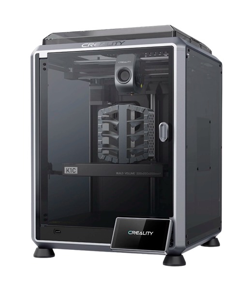
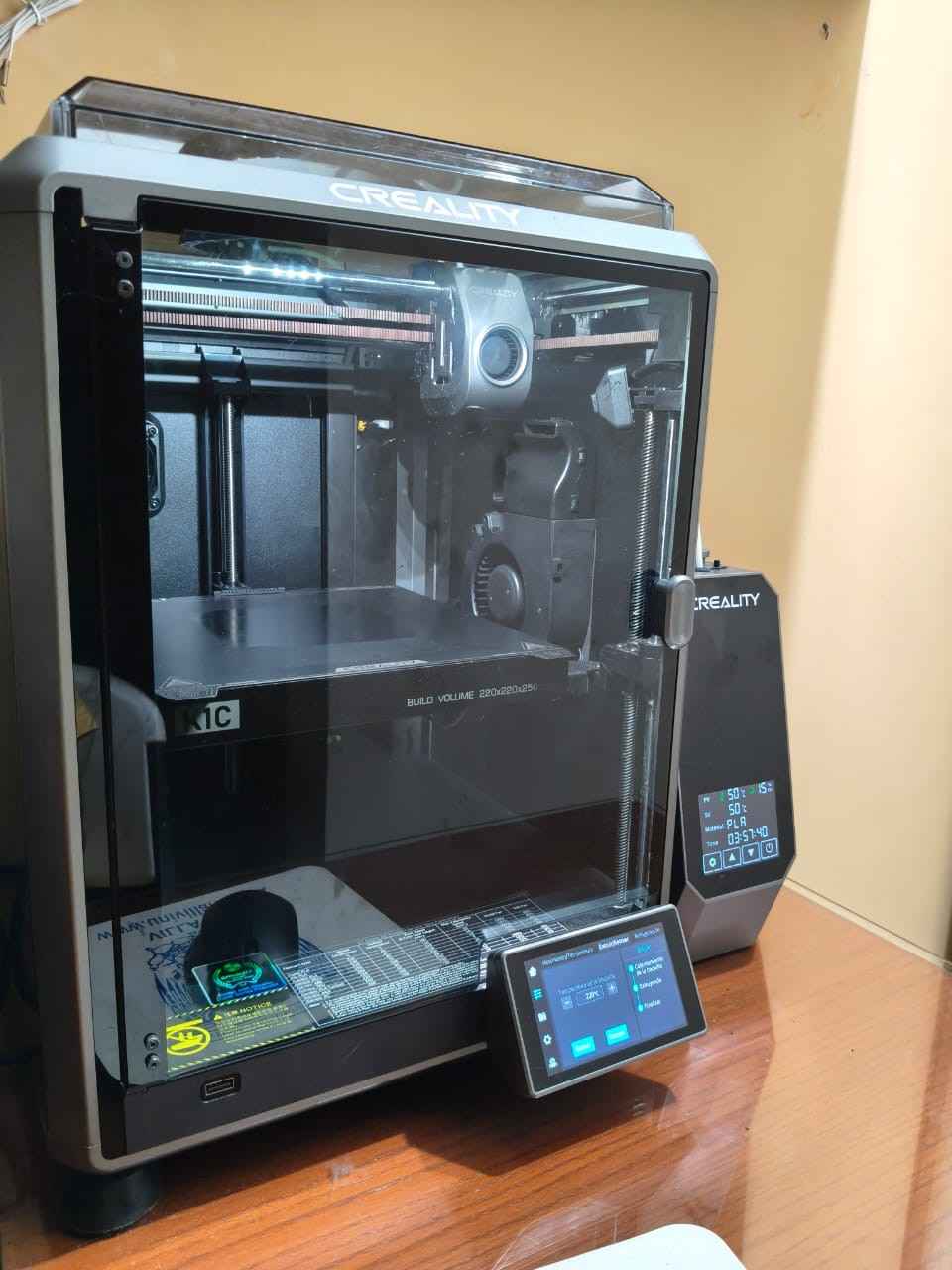
For this week's assignment, I used my personal Creality K1C 3D printer, an enclosed FDM printer with a CoreXY motion system. This printer comes equipped with an AI camera that enables print monitoring and error detection. Aside from autoleveling, this printer features a robust extruder compatible with carbon fiber filaments, which allows the manufacture of stiffer and dimensionally stable parts like drone frames and lightweight structural enclosures. The K1C has the following specifications:
- Printing Technology: Fused Deposition Modeling (FDM)
- Build Volume: 220mm x 220mm x 250mm
- Printing Speed: 600mm/s (maximum)
- Resolution: 100±0.1mm
- Layer Height: 0.1mm to 0.35mm
- Nozzle Temperature: 300°C (maximum)
3.3D printing
The first task of this week's assignment is to design and "print" an object that is difficult to produce subtractively. Print-in-place mechanisms (PIPs) are an example of such an object. 3D printers can deliver individual components that can be bolted together to form a mechanism. However, the output of some mechanisms may be required in a tight space, which may prove to be insufficient to house a traditional mechanism assembled with nuts and bolts. In such situations, 3D printing enables the creation of fully integrated complex mechanisms that eliminate the need for additional assembly steps.
As mentioned on my Final Project page, I want to improve the design of the wheels of my robot, particularly their bolted joints. Nuts and bolts hold the wheel components together, but after continuous spinning, these fasteners tend to loosen or even detach. As the wheels require hinges for their opening and closing motion, I have decided to evaluate print-in-place rolling hinges. Correct placement of print-in-place hinges could allow the manufacture of the wheels with fewer components, particularly those that tend to loosen and detach.
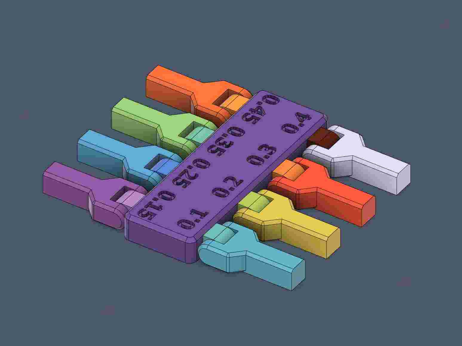
To design a 3D object with print-in-place rolling hinges, I first conduct a tolerance test for print-in-place hinges. I used the print-in-place tolerance test test uploaded to Printables by the user Windrose. This tolerance test includes spacings from 0.1mm to 0.45mm.
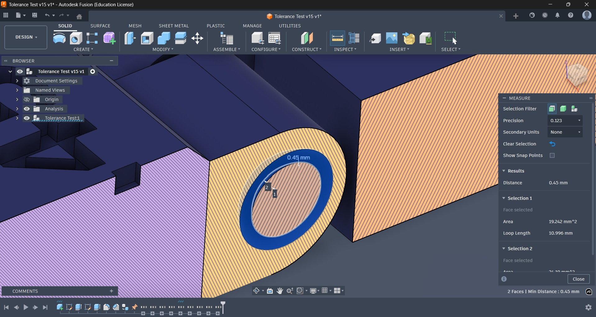
Before proceeding with printing the tolerance test, I first checked the CAD file downloaded from Printables. I used Fusion 360 to inspect the test model by performing a section analysis, which ensured that the tolerances matched the text labels on the main body of the tolerance test.
3.1.Slicer
3D printing involves using a slicer, which is a software tool that converts a 3D model into G-code instructions. These instructions guide the printer in creating 2D horizontal layers that are deposited to produce a physical copy of the original 3D model. I choose to use Creality Print 7.0, the slicer provided by Creality for controlling their printers, like the K1C.
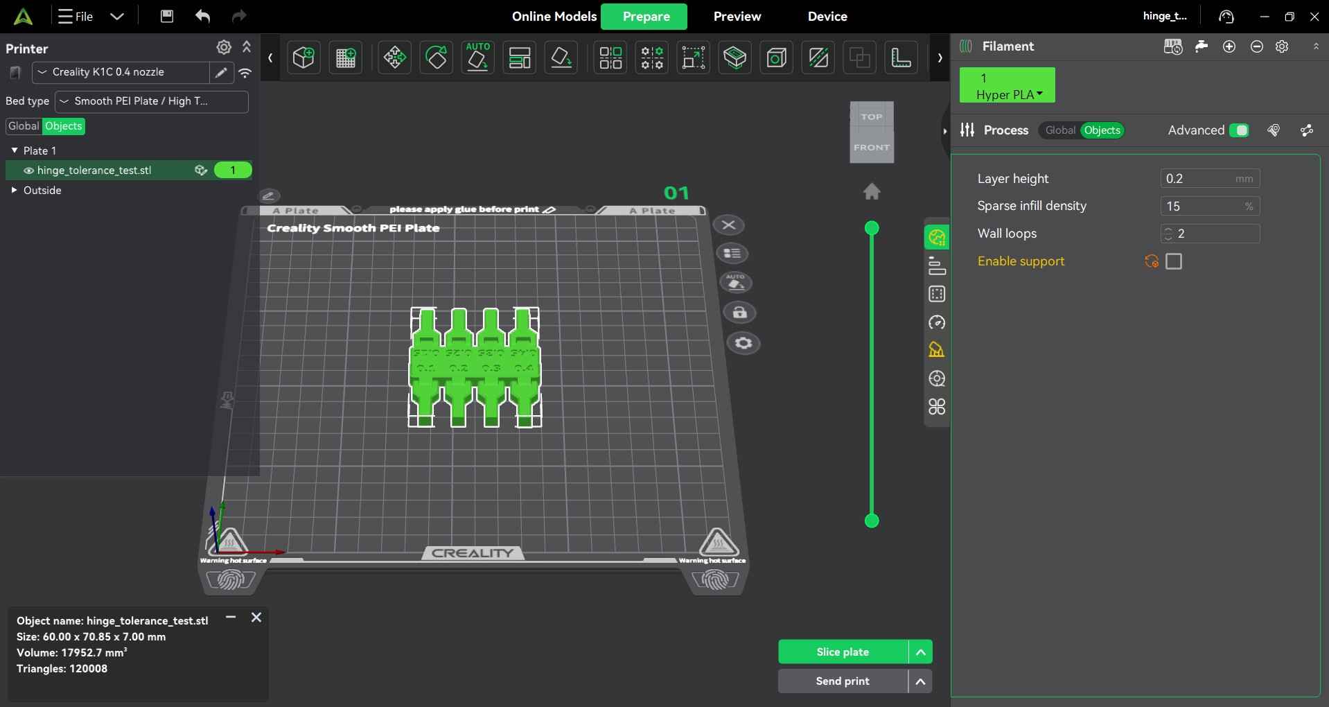
After downloading and installing Creality Print, opening the software will show its main interface. By default, the slicer opens in the "Prepare" window, where users can configure printers and select materials.
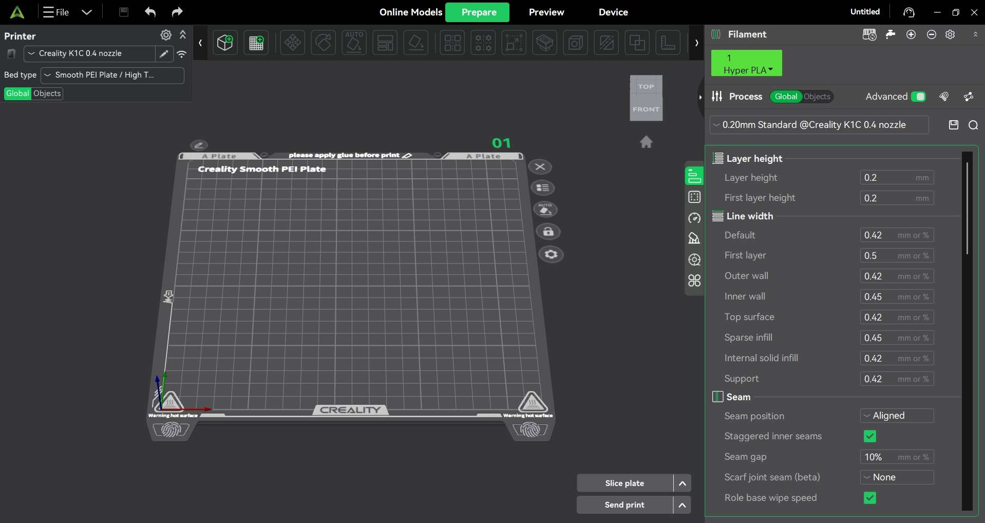
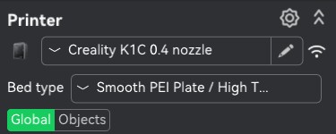
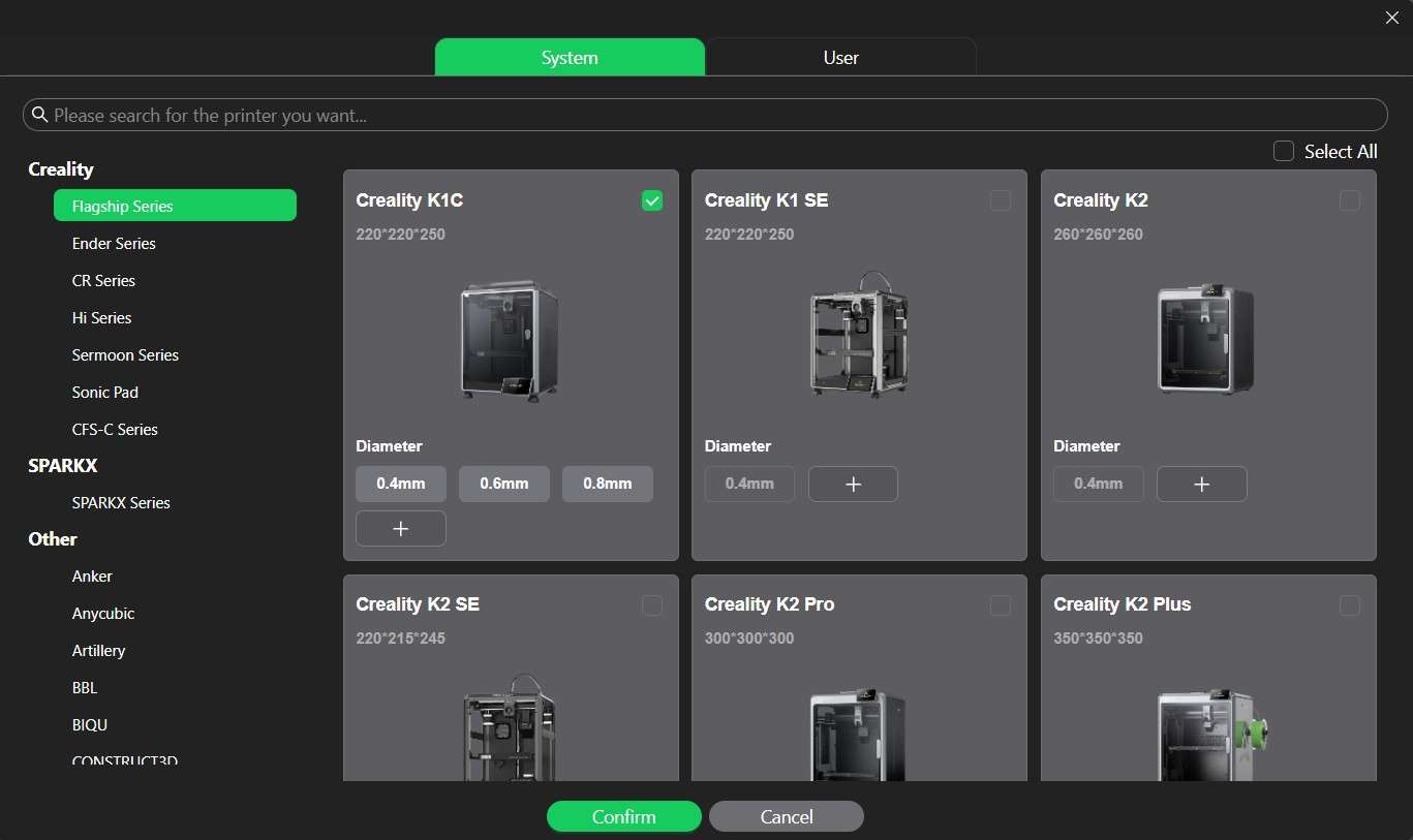
On the upper left side of the interface, there is the "Printer" menu, where users can download presets for proprietary 3D printers from Creality and other brands. These presets include nozzle diameters officially provided by Creality. In my case, I choose the Creality K1C with a 0.4 mm diameter.
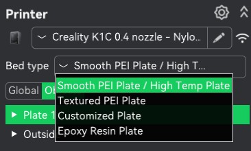
This menu also allows users to choose the bed type; this choice depends on the material that will be used to print an object. I choose the Smooth PEI Plate/High Temp option, given that I was planning on printing my design on PLA, a material that can be handled by this particular plate.
Users can select the material to print an object from the "Filament" menu on the left side of the interface. This menu also allows users to customize print quality, strength, speed, support, and multifilament use. Quality includes parameters such as layer height, width, seam, precision, overhangs, bridging, and wall generation. The strength category allows users to tweak parameters such as wall loops, top surface pattern, and infill. Given that 3D printing creates grid patterns to fill an object, the strength category can be considered synonymous with durability. The speed category lets users configure the speed at which the nozzle deposits each layer. Support lets users add sacrificial layers of material deposited by the nozzle to achieve complex shapes. The multifilament category lets users configure the Creality Filament System to incorporate different materials on a single print.
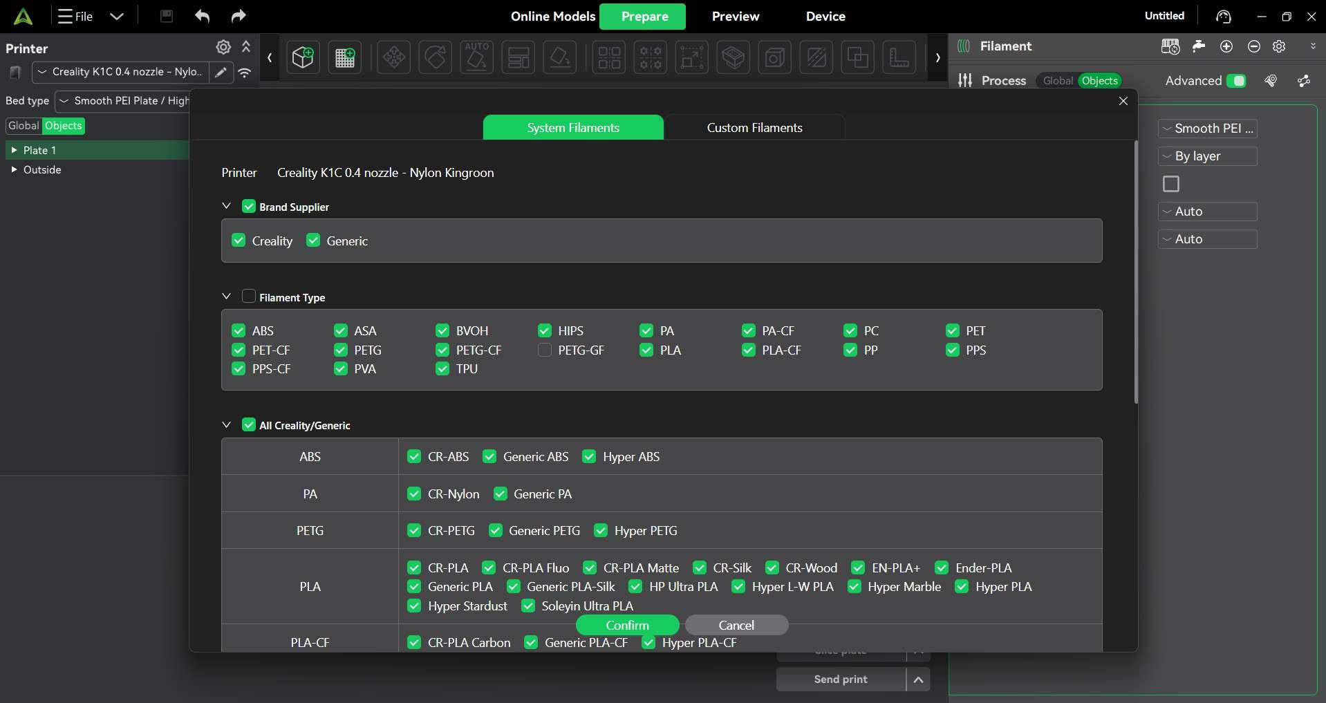
The "Filament" menu also contains the "Set Filaments to use" option, which lets users download filament profiles from Creality. Unfortunately, this slicer does not contain filament profiles from other brands; instead, users have to download generic profiles for a desired material and adjust its parameters.
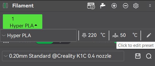
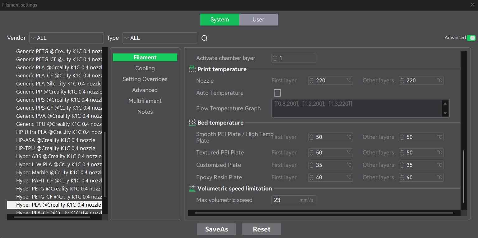
To review and edit the parameters for a material profile, click on the arrow next to the material name inside the green box on top of the filament menu. This will open the "Filament settings" menu.
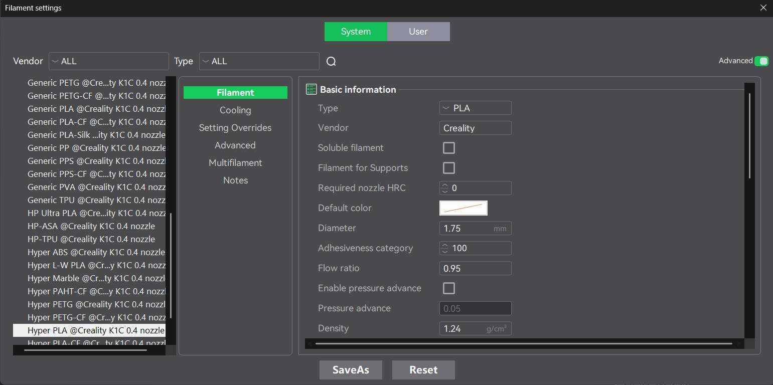
Filament settings are divided into the following categories: filament, cooling, setting overrides, advanced, multifilament, and notes. The filament category includes basic information about the material, such as its type, vendor, solubility, flow ratio, density, color, price, nozzle temperature, chamber temperature, and bed temperature. The cooling category helps configure at which layers of the print model, nozzle, back, and side fans of the K1C printer will be active. The setting overrides include all aspects related to material retraction, such as retraction speed, deretraction speed, and the option for "hoping." The multifilament category includes options for tool change and wipe tower parameters. The notes section shows a textbox in which users can write relevant information about that specific filament.
The upper bar of the interface contains options for placing and editing objects that will be printed. These options become active the moment a printable file is imported into the software.
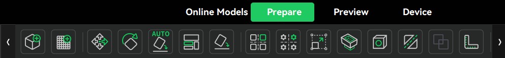
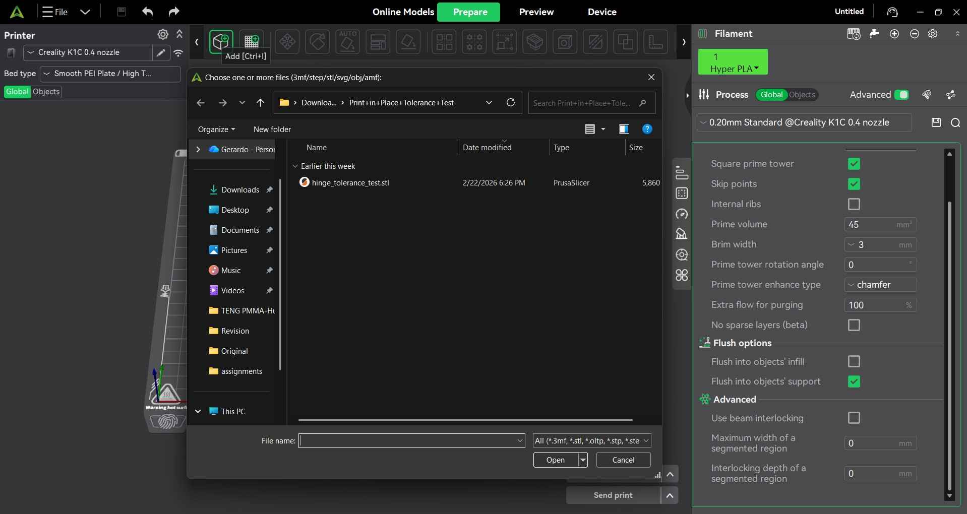
Files are imported by clicking on the add icon, which is at the far left side of the upper bar. Clicking on this icon will open the file browser and show files with compatible formats. The computer I worked on also had Prusa Slicer installed; as such, printable files are shown with that extension; however, this fact does not cause trouble when I try to open any printable file on Creality Print 7.0.
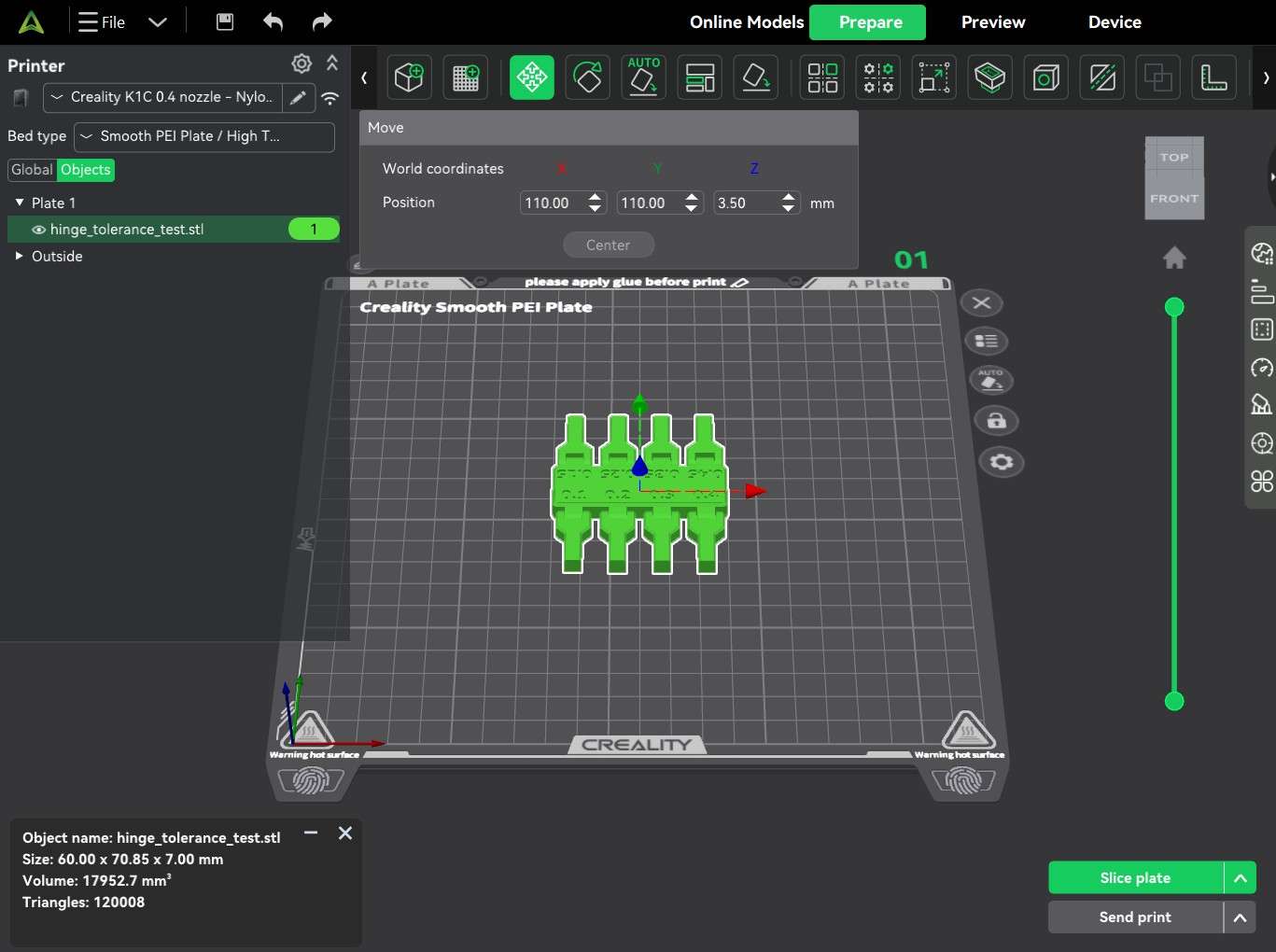
The third icon on the upper bar is the "Move" button; after importing a file, we may want to change its position on the print plate. Selecting the object we want to move and clicking on the "Move" button will show a menu with options to change the object's position on the X, Y, and Z axes.
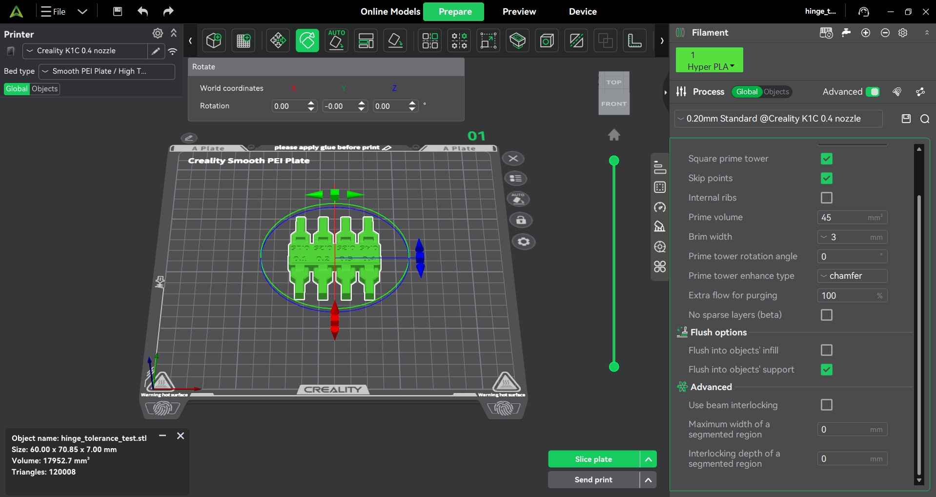
The fourth icon on the upper bar is the "Rotate" button; similarly to the "Move" button, by selecting an object and clicking on this button, we can rotate an object around the X, Y, and Z axes.
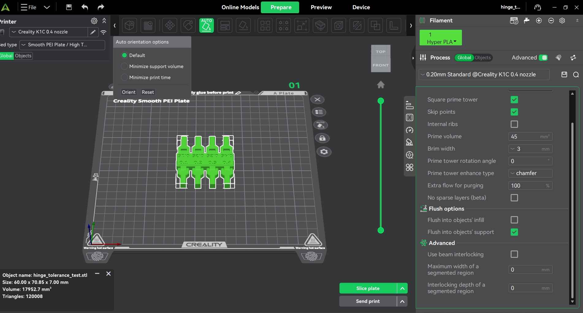
The fifth icon on the upper bar is the "Auto orientation options" button. Sometimes, when an object is imported, the slicer places it in a position that would require support materials or otherwise be impossible to print. This button provides options to minimize support volume or print time.
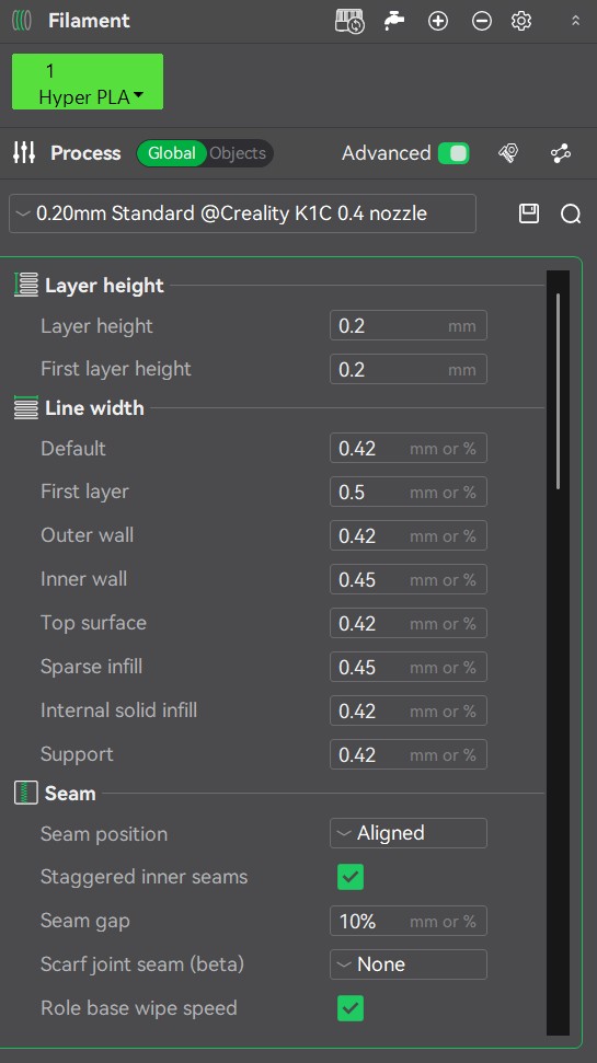
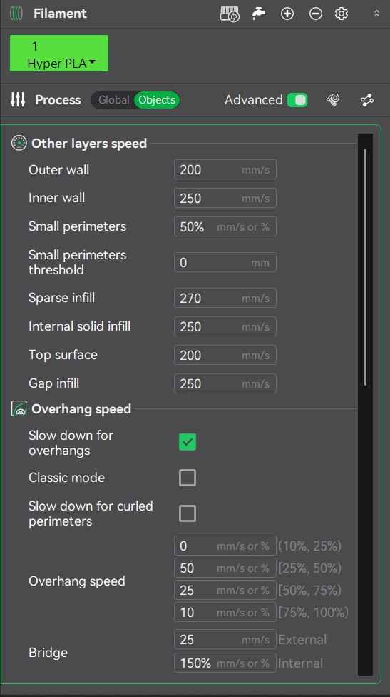
With the print tolerance test already in a position for optimal printing, I chose Hyper PLA filament as the material for this print. This material is sold by Creality for printers like the K1C. The Hyper suffix is used by Creality to denote that this particular PLA is designed for high-speed printing. I selected the default settings for this material, which include a nozzle temperature of 220°C, a bed temperature of 50°C, an outer wall print speed of 200 mm/s, an inner wall speed of 250 mm/s, and an internal solid infill speed of 250 mm/s. For print quality, I used a sparse fill density of 15% and a grid infill pattern, as I didn't need this print to be sturdy. I also used a layer height of 0.2mm, which could be handled by the 0.4mm nozzle extruder on my K1C.
Global print configuration
Hyper PLA temperature parameters
Hyper PLA speed settings
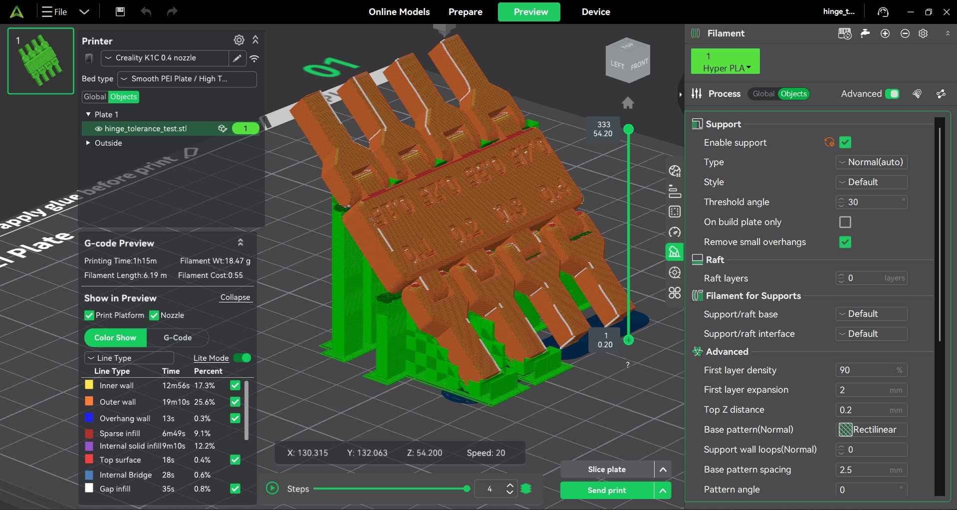
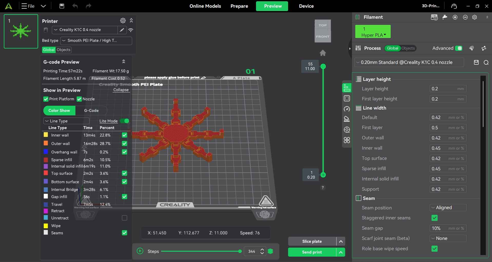
With the material parameters checked, I proceeded to click the "Slice Plate" button. This command will begin the process of "slicing" a 3D model in 2D layers. The slicer interface now displays the "Preview" window, which shows the sliced layers of the 3D model. provides some relevant information about the generated G-Code, like estimated printing time and filament use.
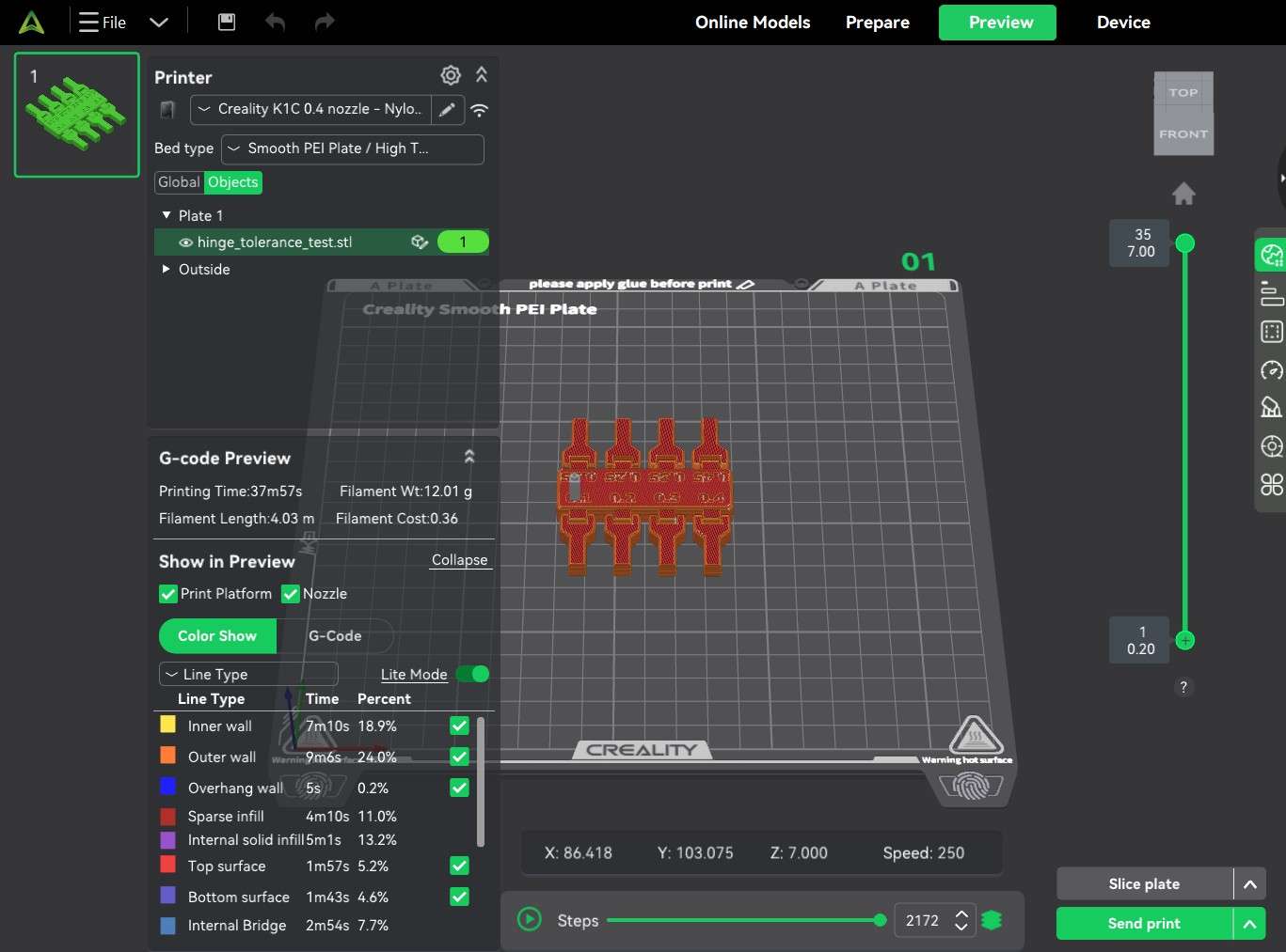
As a sidenote, this window also shows results from support material generation. This print didn't require support material, as the auto-orientation option of the upper bar placed the object in a position that did not require it. However, I rotated the object along the x axis to show the results of a hypothetical support material generation.
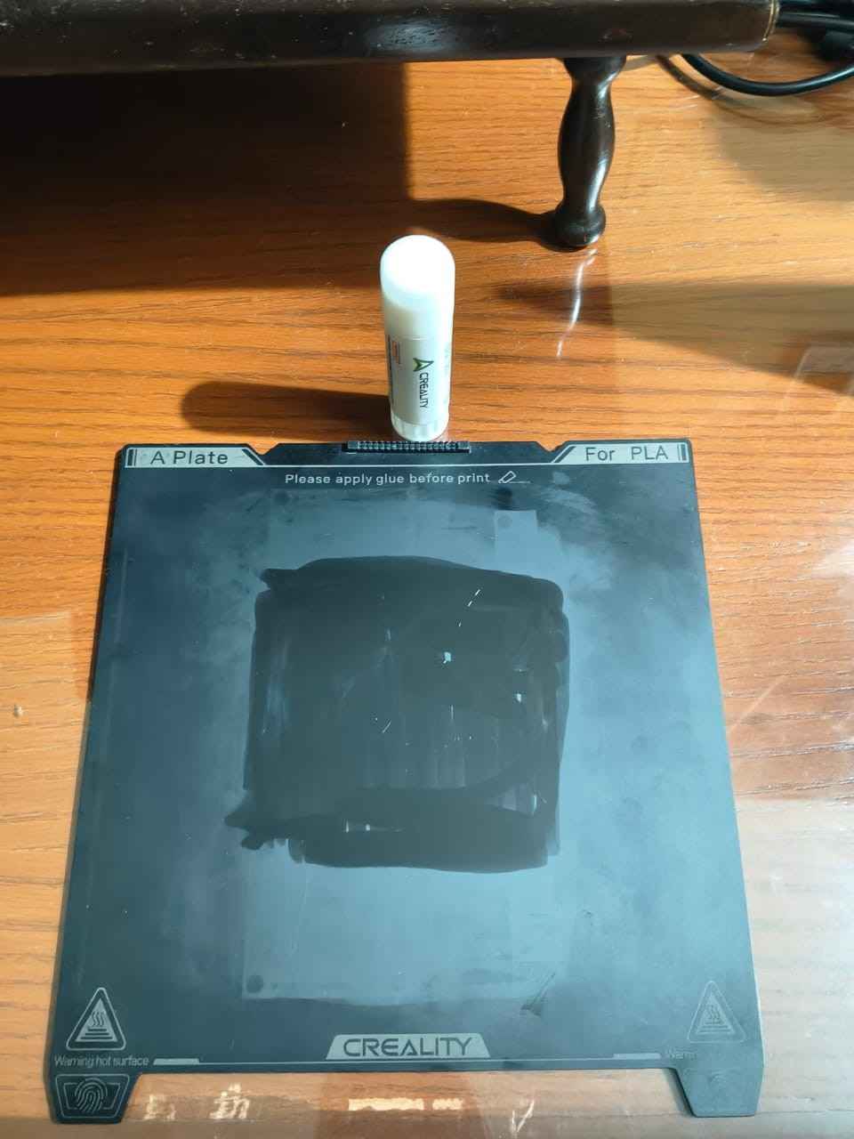
Before proceeding to print my object, I decided to prepare my smooth PEI plate. I washed it with water and then used isopropyl alcohol to erase my digital fingerprints. With the plate dried, I covered the center with glue rated for PLA, ABS, PETG, PC, PA, and TPU. I decided to apply glue to ensure maximum first-layer adhesion.
After the plate was prepared and placed on the printing bed inside the K1C, I turned on the printer and the filament dryer. I printed in Boca del Río, Veracruz, a humid city, so I decided to dry my filament before and during the printing process.
SWith the 3D printer prepared, I clicked the "Send Print" button. This action brought up the "Device" window in the slicer interface, allowing users to select the printer to which they would like to send the G-code. As my K1C was already active and had a stable Wi-Fi connection, I clicked the "Start print" button.
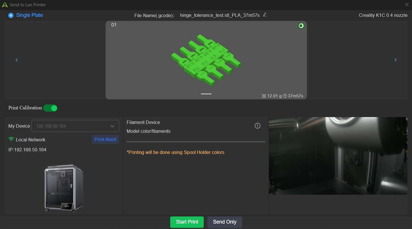
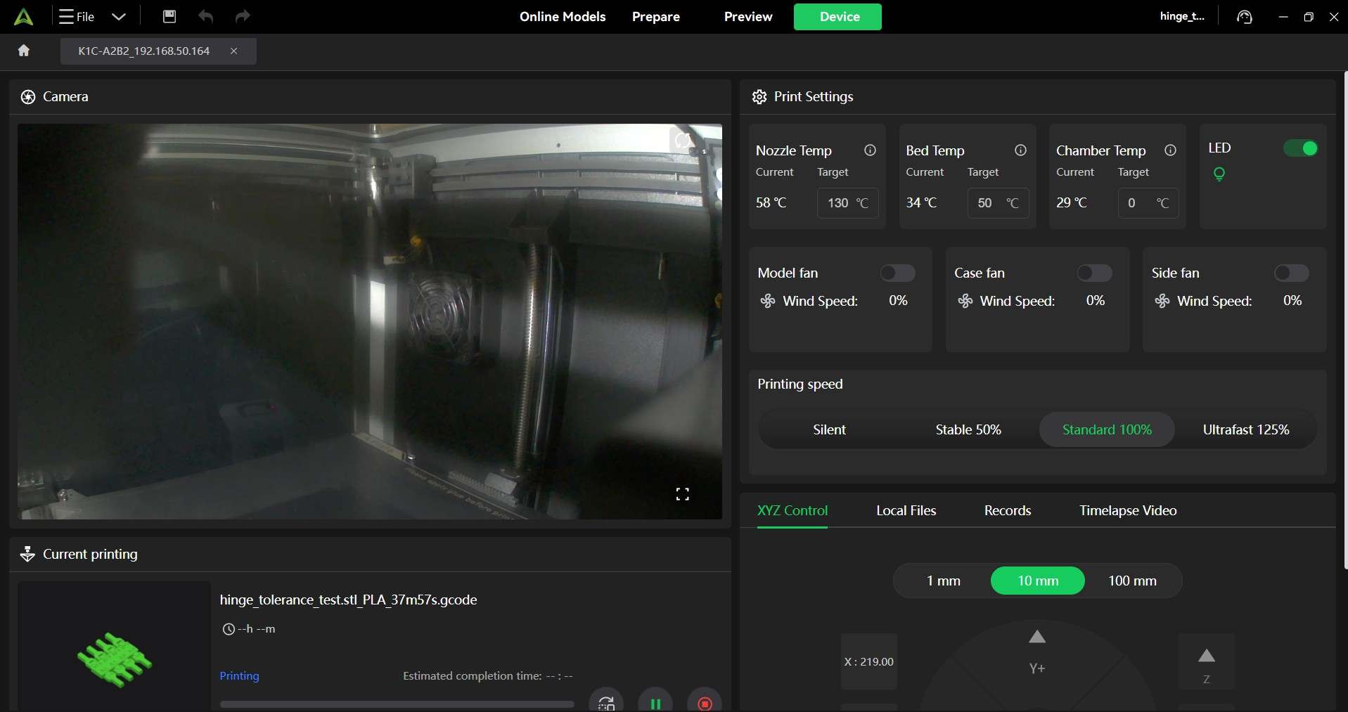
Clicking the "Start print" button will prompt the slicer interface to show the "Device Window," which shows a panel for real-time monitoring and control. When using a K1C, this panel also shows video footage from the camera housed within the printer.
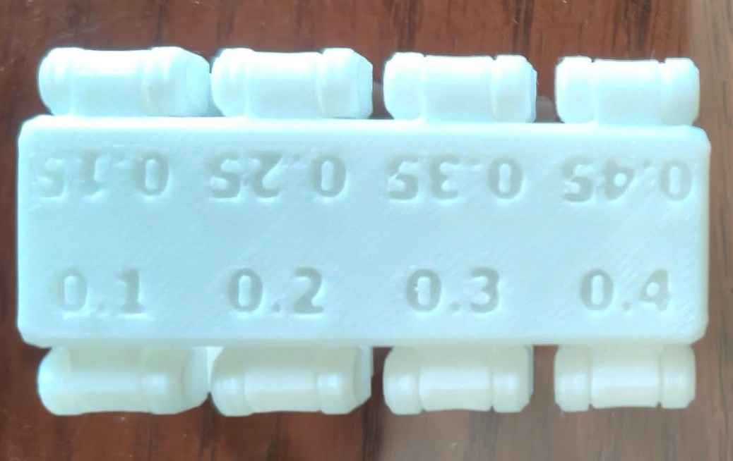
After completing the print, I removed the object from the printing bed and began rotating each hinge to assess how closely I could design print-in-place rotating elements.
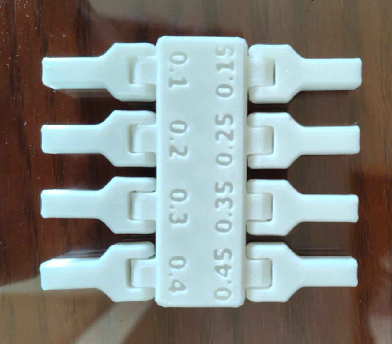
Each one of the eight hinges from the test rotated; the 0.1 hinge proved to be the most difficult to loosen and rotate; however, this may make it suitable for prints that require reliable poseability.
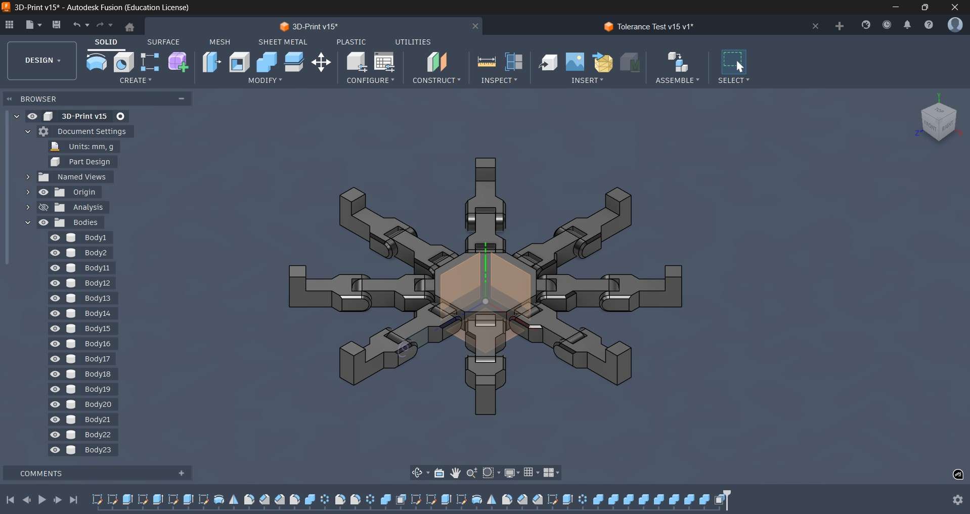
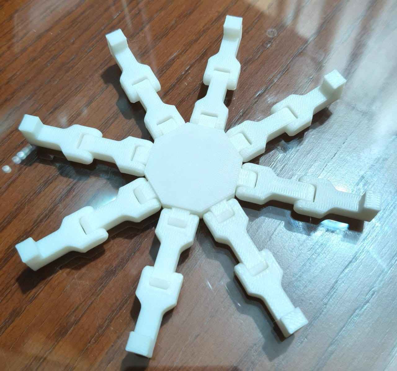
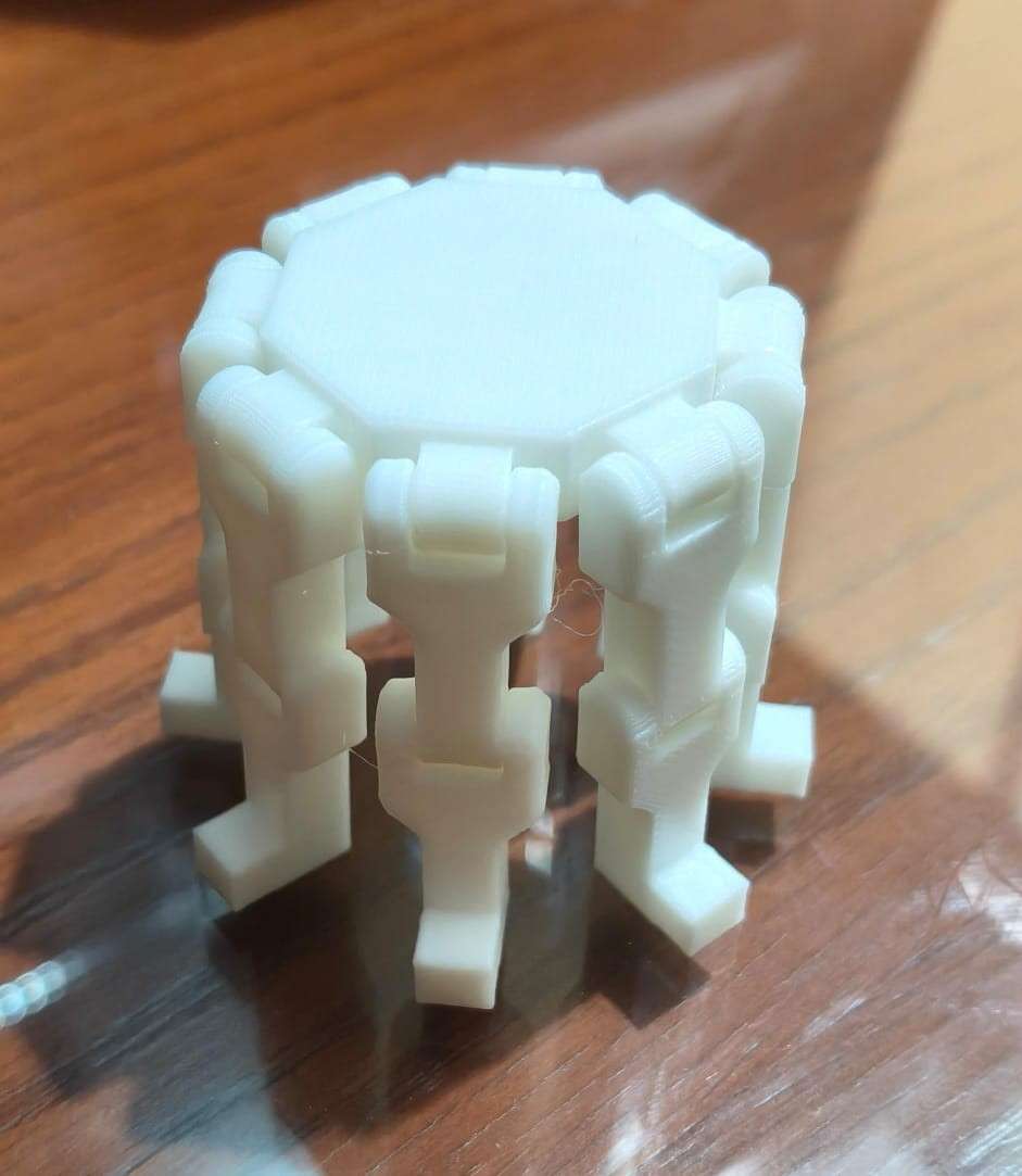
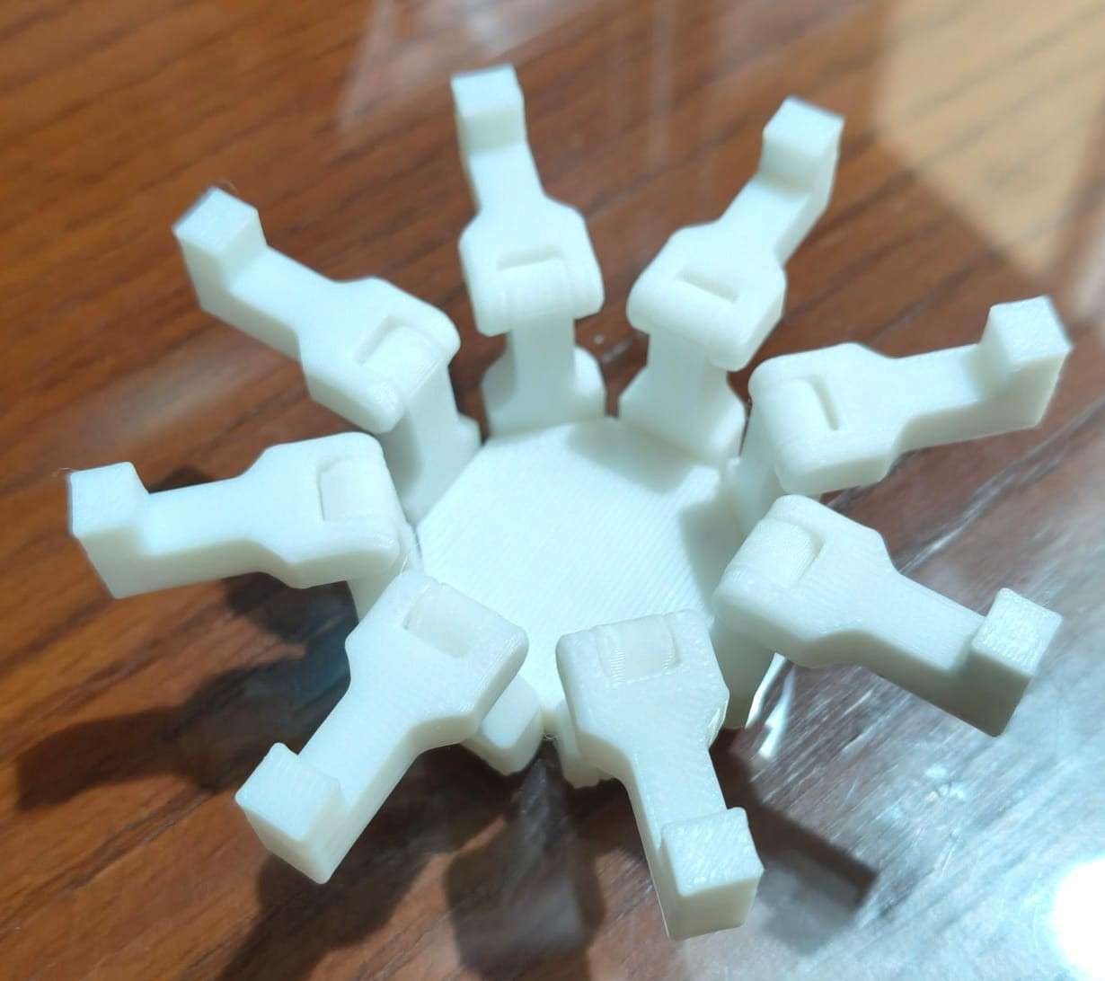
4.My design
This was my first experience designing a print-in-place mechanism, even though I had previously printed one for the print tolerance test. I don’t view myself as an imaginative person, so I chose to concentrate on my thought process while completing this week's assignment. I plan to present a new version of my robot as my final project; the last iteration of my robot was often likened to a spider rather than a six-legged insect. Therefore, I decided to print an eight-spoke structure with rolling hinges. I hope this activity will help me learn how to design and 3D print rolling hinges, as I plan to use them for the opening mechanism of my robot's wheels.
I decided to create a 3D model of my structure using Fusion 360. As the first step, I established key parameters, including the tolerance for the rolling hinges, the length of the polygon sides, and the dimensions of the anchors. I chose a 0.1 mm tolerance, as I wanted the joints to be as tight as possible.
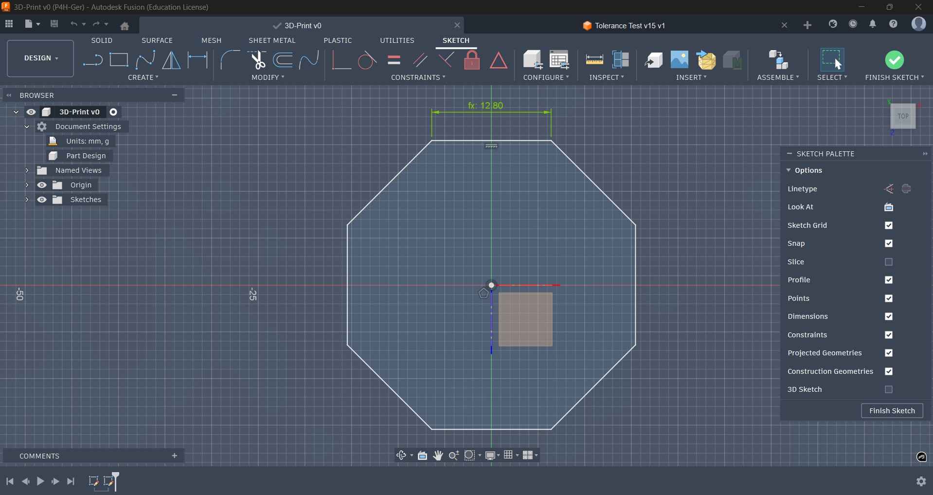
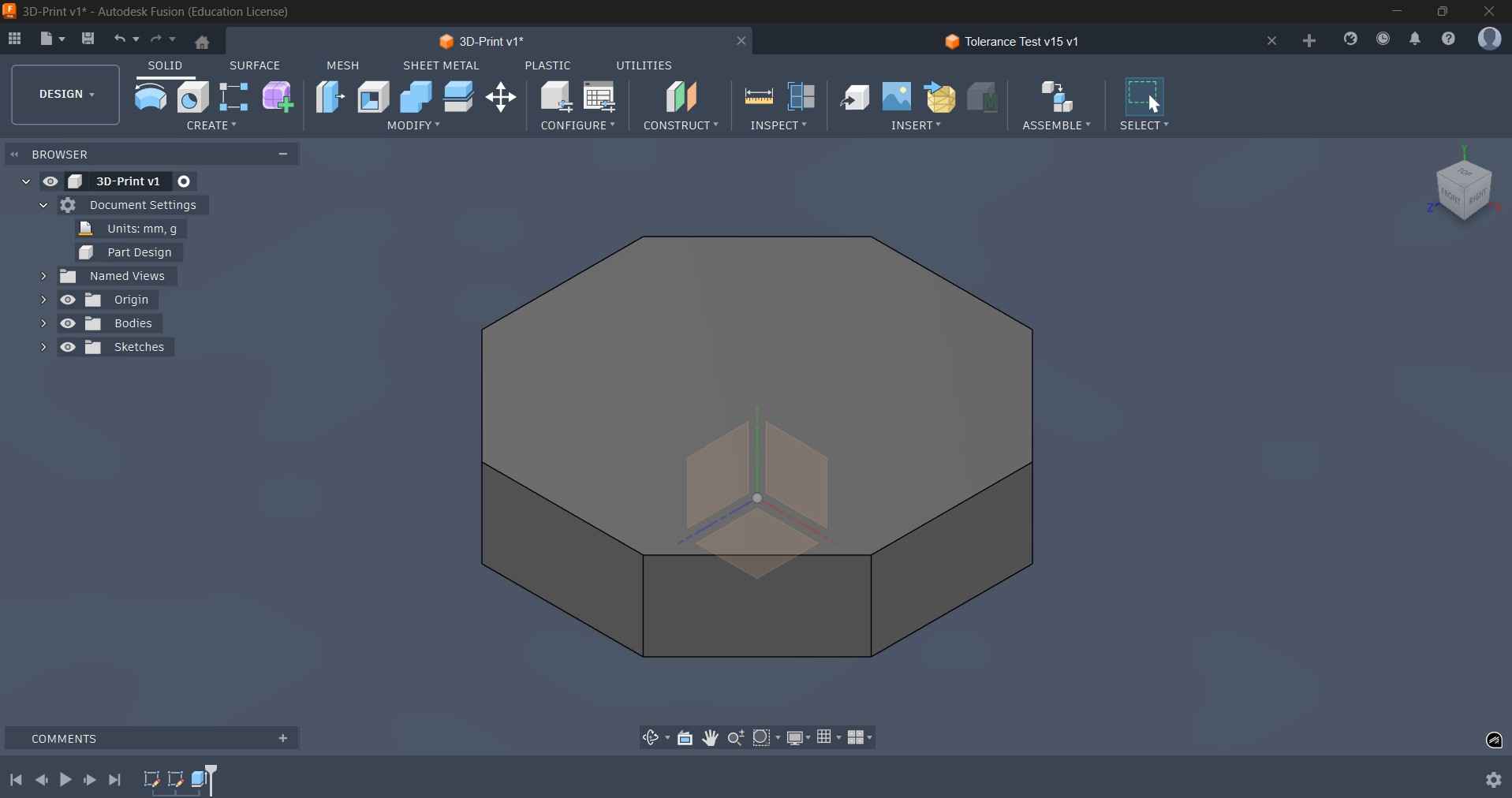
I began my design by sketching an octagon, with the length of its sides determined by the length of the polygon sides parameter. After finishing the sketch, I extruded the octagon to create the base structure.
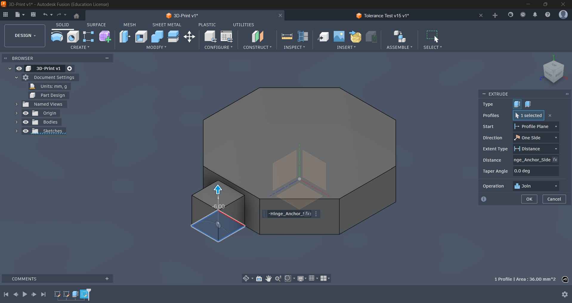
With the base polygon finished, I moved on to sketching the anchor that would allow a link to roll, thereby completing the hinge mechanism. I used the corresponding parameter to size this sketch; this same parameter was used to extrude the sketch of the anchor.

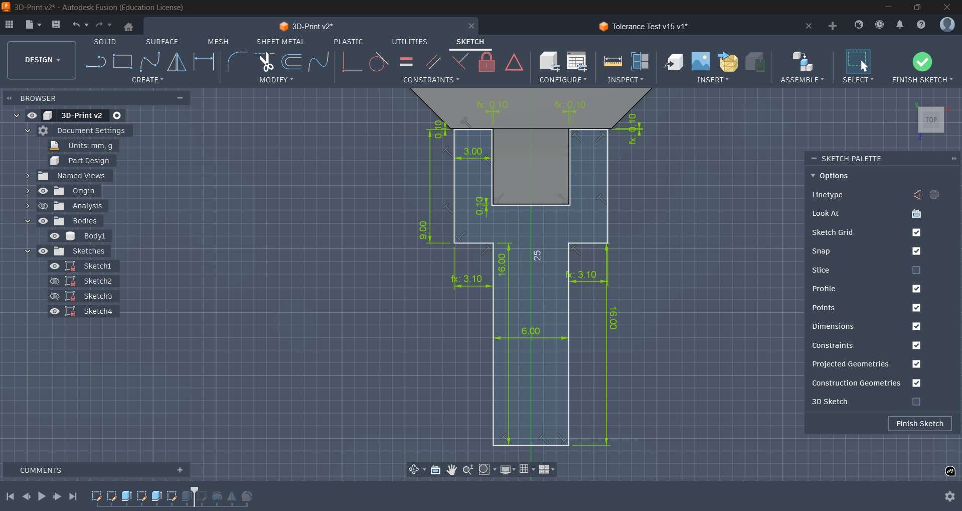
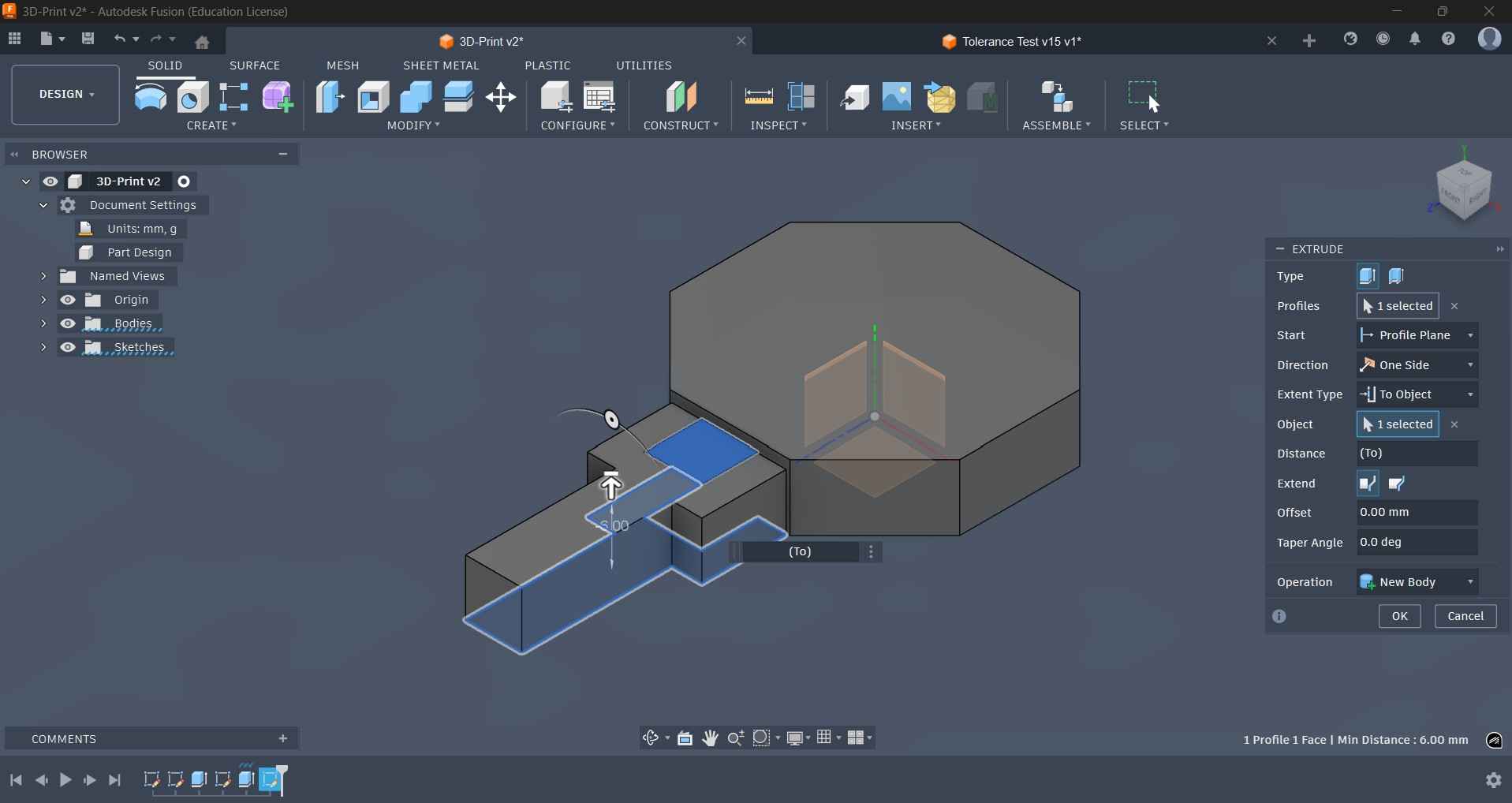
After extruding the anchor, I proceeded to create the sketch for the link that completes the mechanism. I used the tolerance parameter to ensure the sketch was appropriately spaced from the anchor, which allows for rotation. I then extruded this sketch using the same length that was applied to the anchor.
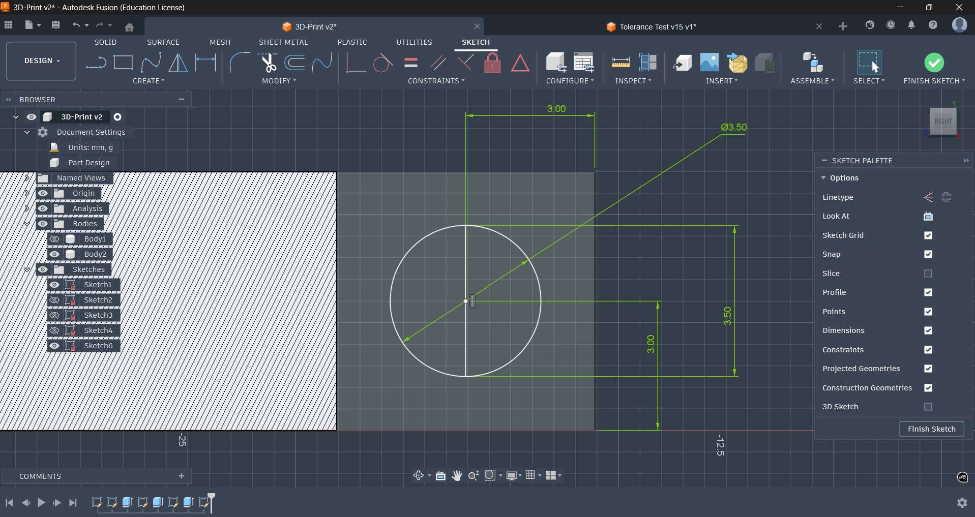
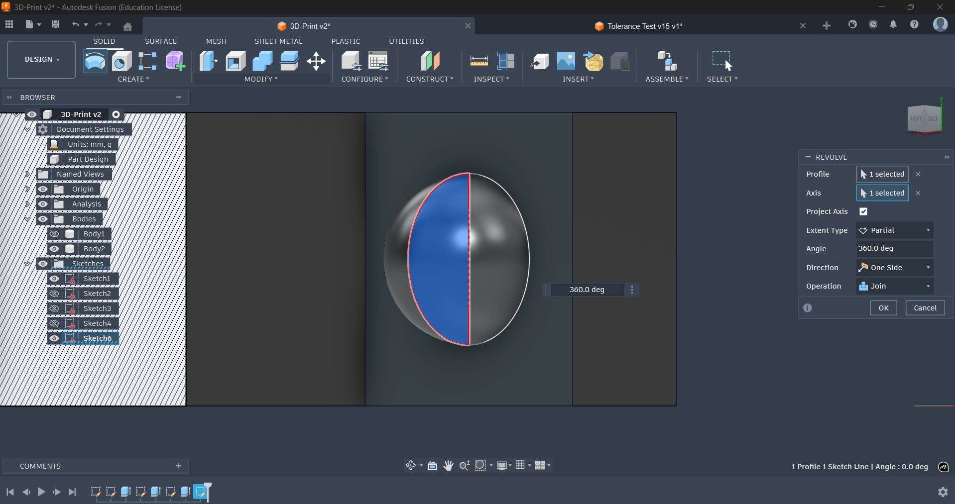
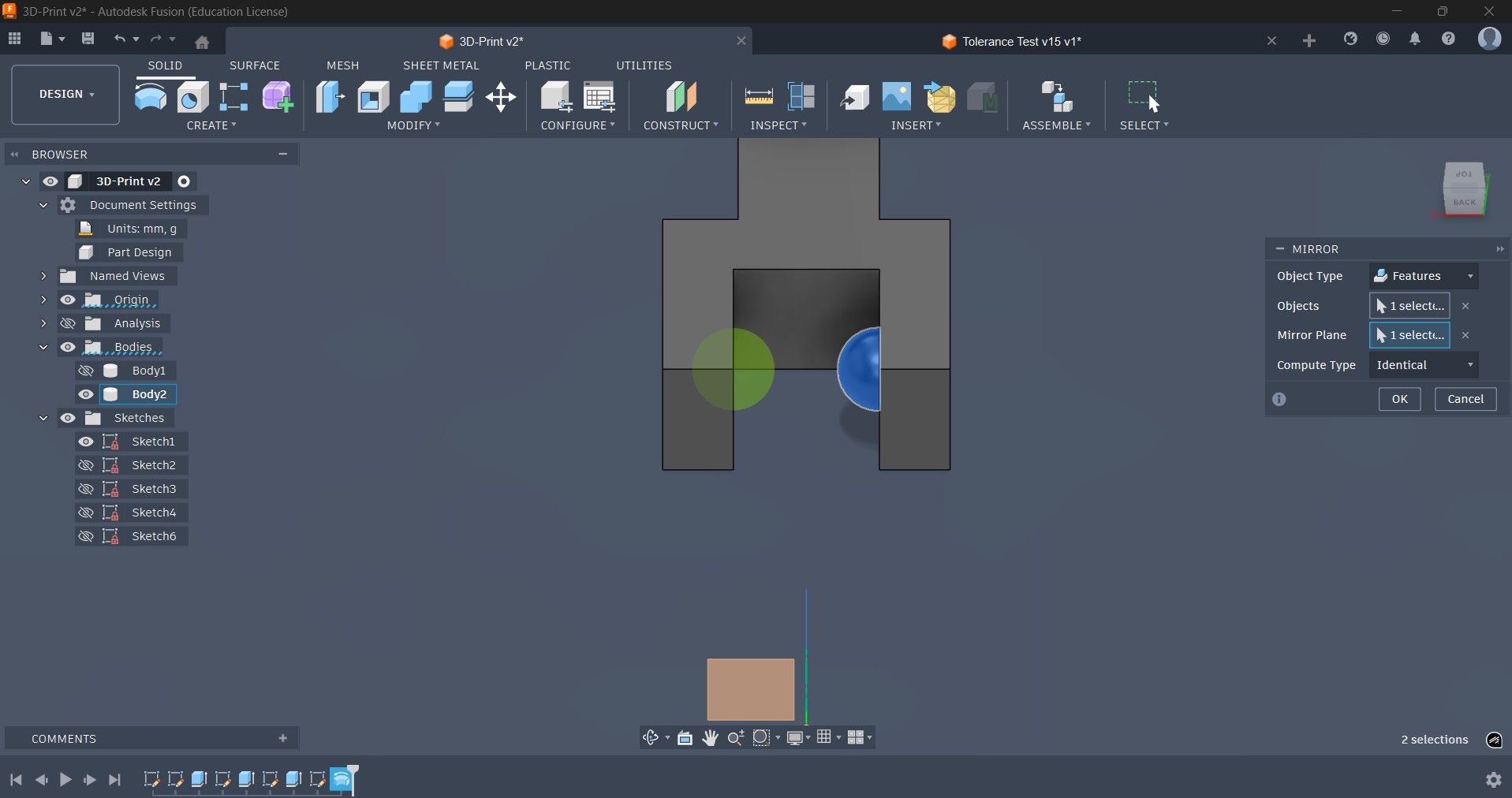
After the link was extruded, I hid the main body to access its inner faces. Using an analysis section, I was able to access the surface I desired to use for sketching the round peg that would rotate around the anchor. With the sketch finalized, I proceeded to use a revolve operation to materialize the round peg. After that operation, I used a symmetry operation to replicate that round peg on the opposite side of the link.
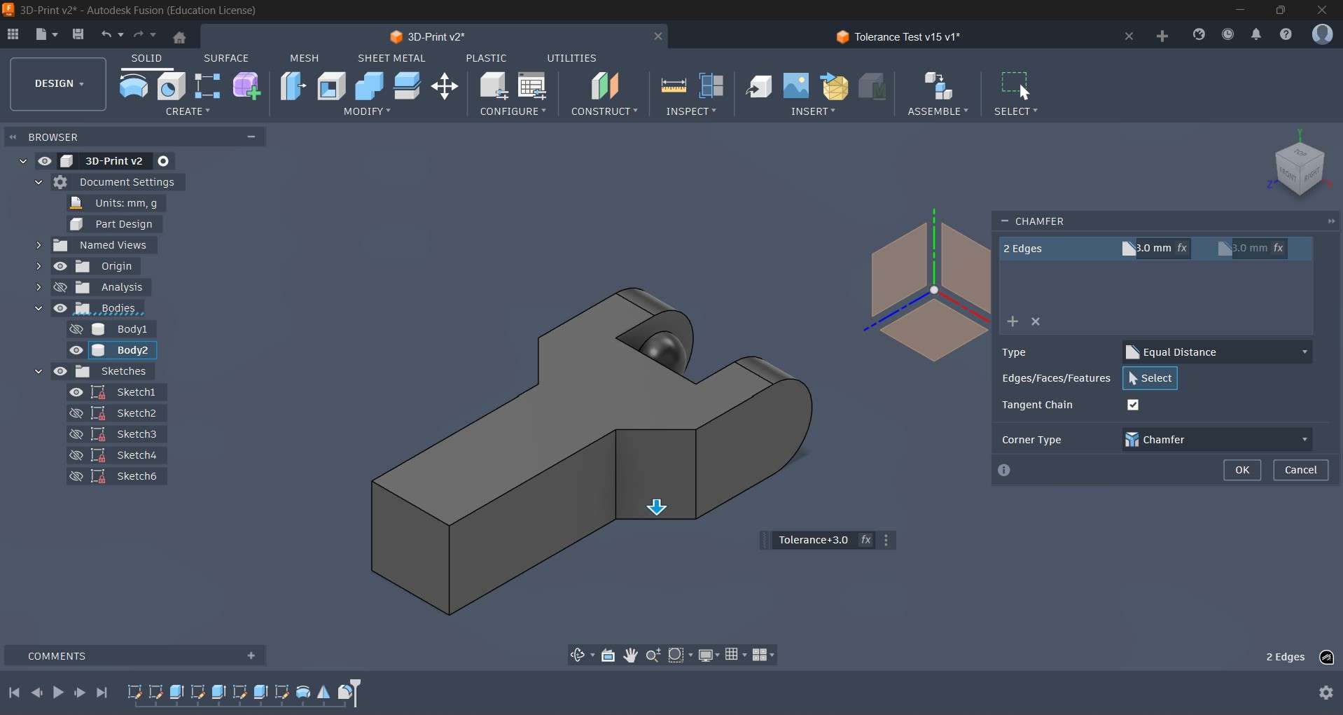
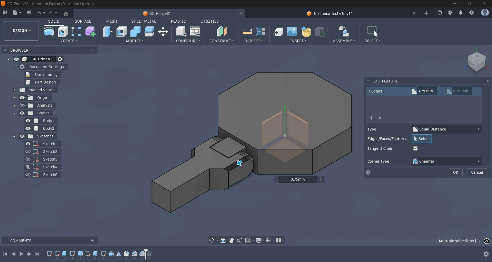
I applied a fillet operation to round the edges closer to the main body of the structure to facilitate rotation.

Chanfers were also applied to the edges of the link to reinforce some areas and to create a smooth geometry.
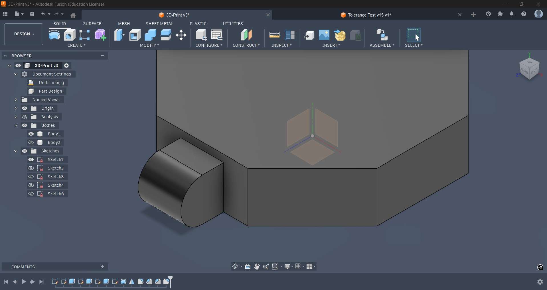
Rounding operations were also applied on the edges of the anchor structure to facilitate smooth rotation. To access this section, the link was temporarily hidden.

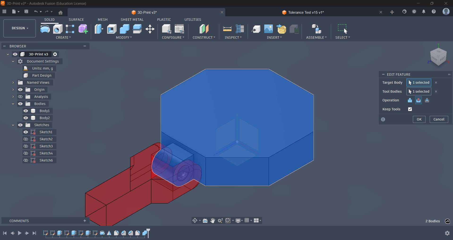
Cavities for rotation around the anchor were created using a cut operation. The round pegs from the link were used as tools to create cavities with the same dimensions.
After creating the cavities, I proceeded to apply a fillet to the flat end of the link. I performed a circular pattern operation to replicate the anchor around each side of the octagon; each of these new anchors also received a fillet operation to round their flat ends. Additional links were also replicated using a circular pattern operation. Circular pegs for each new link were also created using the same procedure for the original.
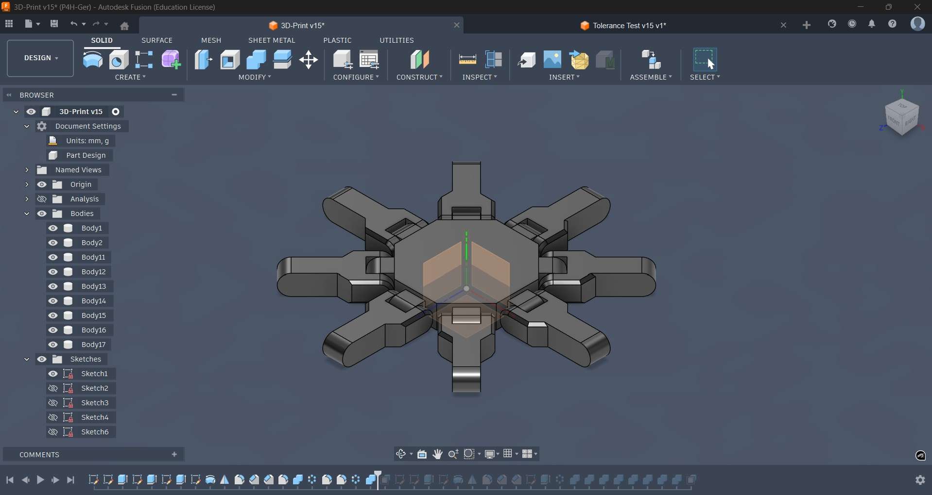
Each of the first eight links received an additional link at its rounded end. This second set of links was similar to the initial batch, except that it now included an extruded surface for added support.
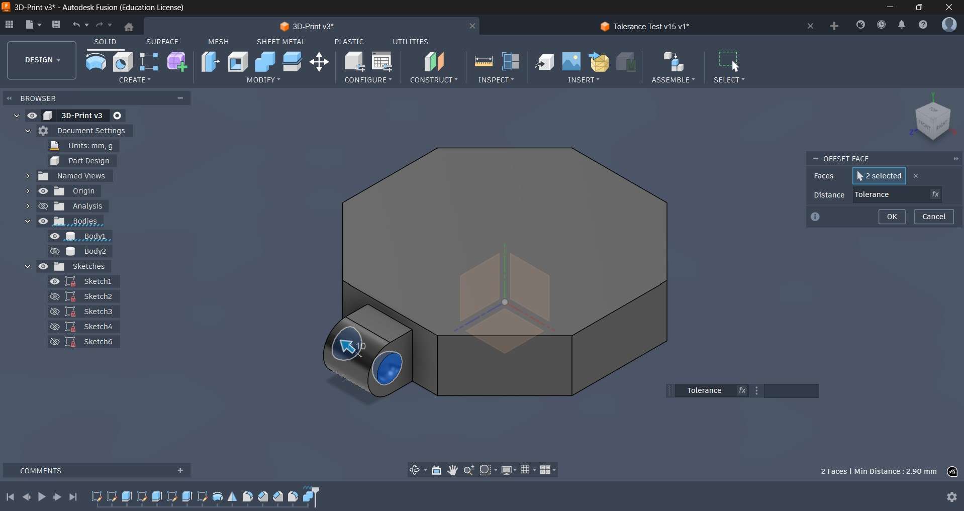
To ensure rotation, each cavity received an offset face operation using the tolerance parameter; the result ensured the appropriate spacing for rotation and posing.
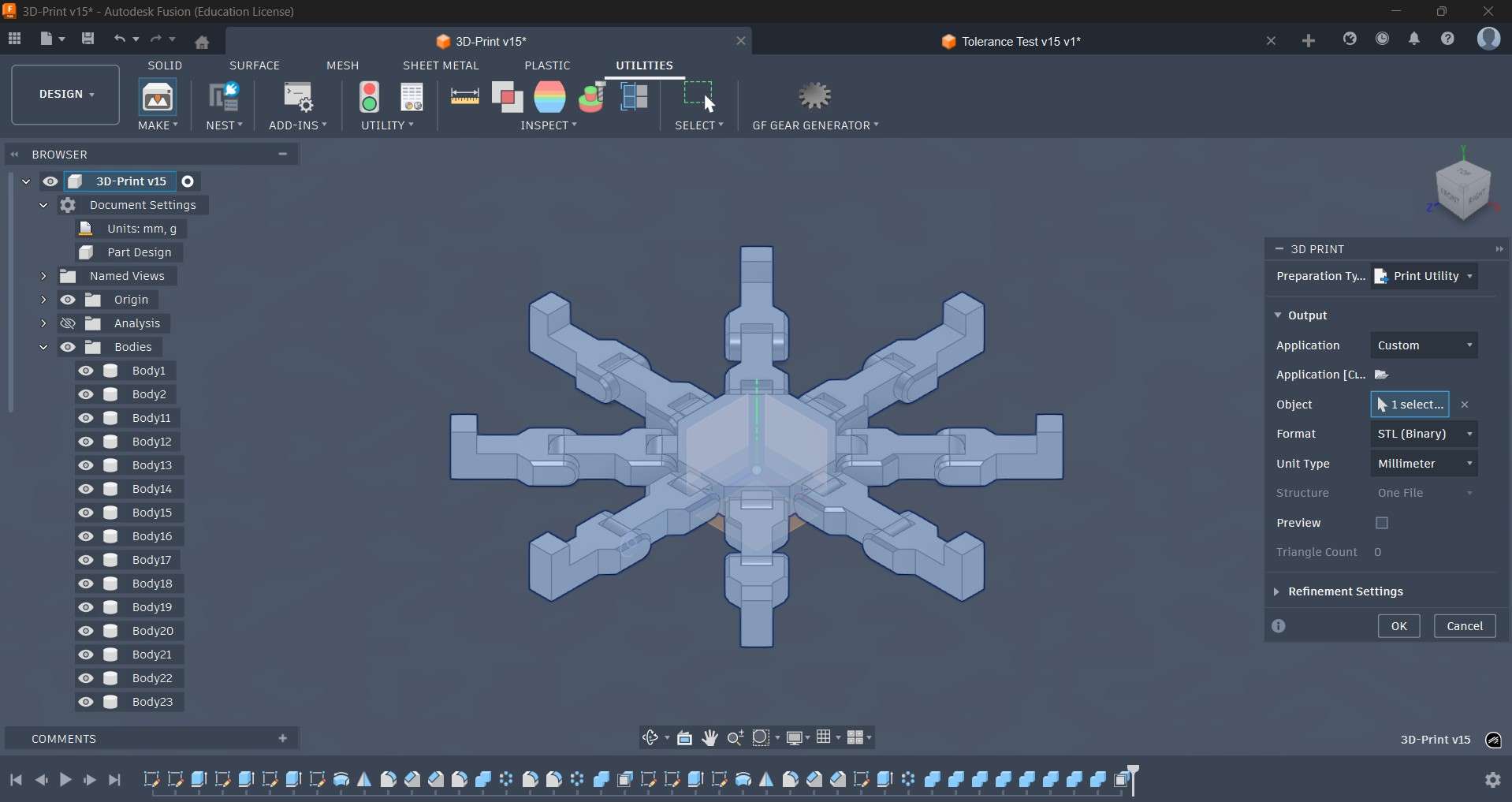
With the design finalized, I proceeded to export it as an STL file using the Utilities menu from Fusion 360. The 3D print option under the "Make" menu opens a window to choose how to output the newly created file. In my case, I chose to directly open it on Creality Print 7.0.
I used the same parameters as the tolerance test to print my design. The K1C printer was also prepared using the same method.
Time-lapse from the K1C camera
Results of the 3D printing process
5.What is 3D scanning?
3D scanning is the process of analyzing a real-world object to capture data about its shape, geometry, and sometimes color. Instead of drawing a model from scratch using CAD, 3D scanning measures the surface of an object to collect points in space. These points can later be converted into a mesh, like an STL or OBJ file.
Common 3D scanning techniques include:
- Laser scanning: This technique uses a laser beam to measure the surface of an object by capturing points in space. The laser is typically projected onto the object and reflected back to a sensor, which measures the distance and angle of each point.
- Structured light scanning: This technique projects a known pattern of light onto an object and captures how that pattern is distorted by the object's surface. The distortion is analyzed to reconstruct the 3D shape of the object.
- Photogrammetry: This technique uses multiple photographs of an object taken from different angles to reconstruct a 3D model. The process involves matching features in the images and triangulating their positions in 3D space.
- Time-of-flight scanning: This technique measures the time it takes for light to travel from a source to an object and back. By measuring this time-of-flight, it calculates the distance to each point on the surface of the object.
6.My scan
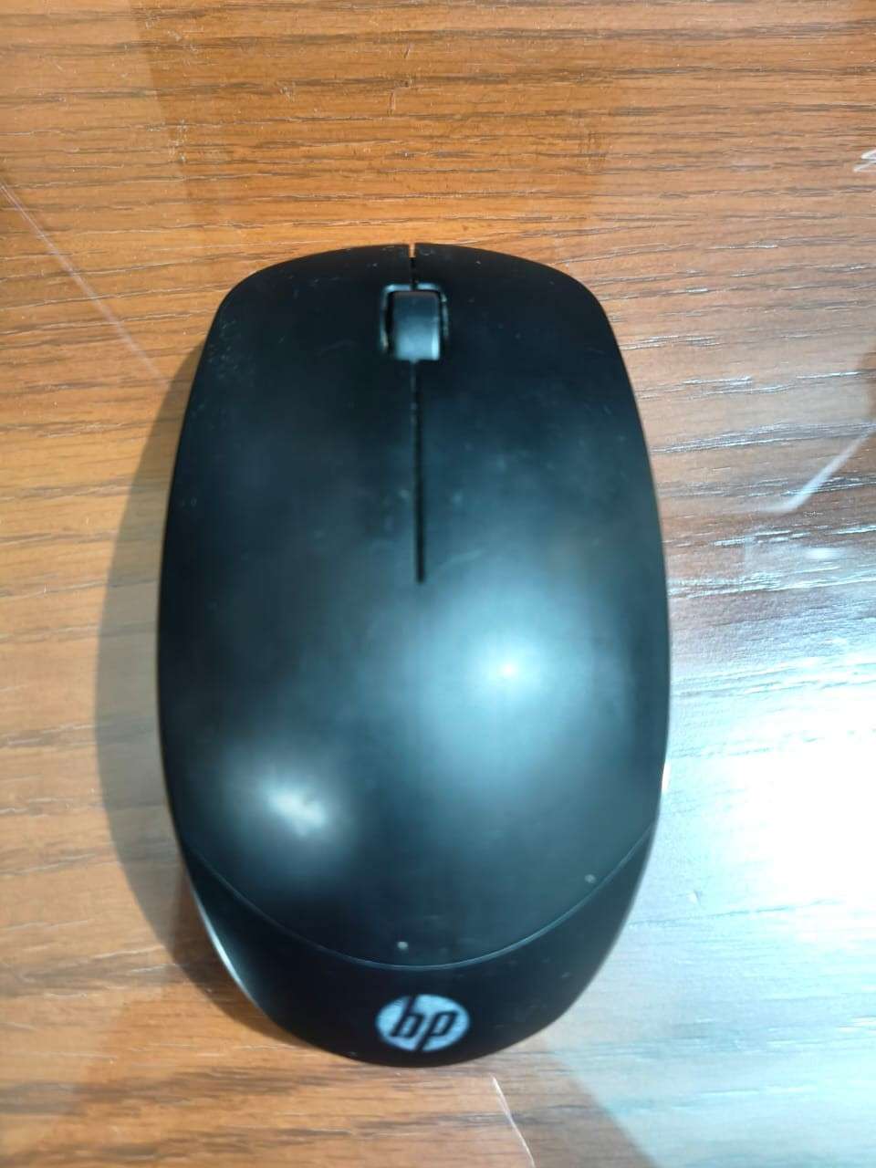
I didn't have access to a 3D scanner at the time of this entry; however, I attempted to use a mobile phone app as an alternative. The app chosen was Kiri Engine. KIRI Engine is a 3D scanning app for Android, iPhone, and web that turns photos into 3D models. Its core focus is photogrammetry, but it also offers other capture methods like LiDAR, 3D Gaussian splatting, and a “featureless object” mode for harder subjects like shiny or low-texture objects. To test the app, I decided to scan my PC mouse. I used 20 pictures to scan it due to processing and time constraints.
6.1. My second scan
I could not get a good scan using the Kiri Engine app. However, when I finally arrived at FabLab Ibero Puebla, I decided it was time to test the scanners available on site.
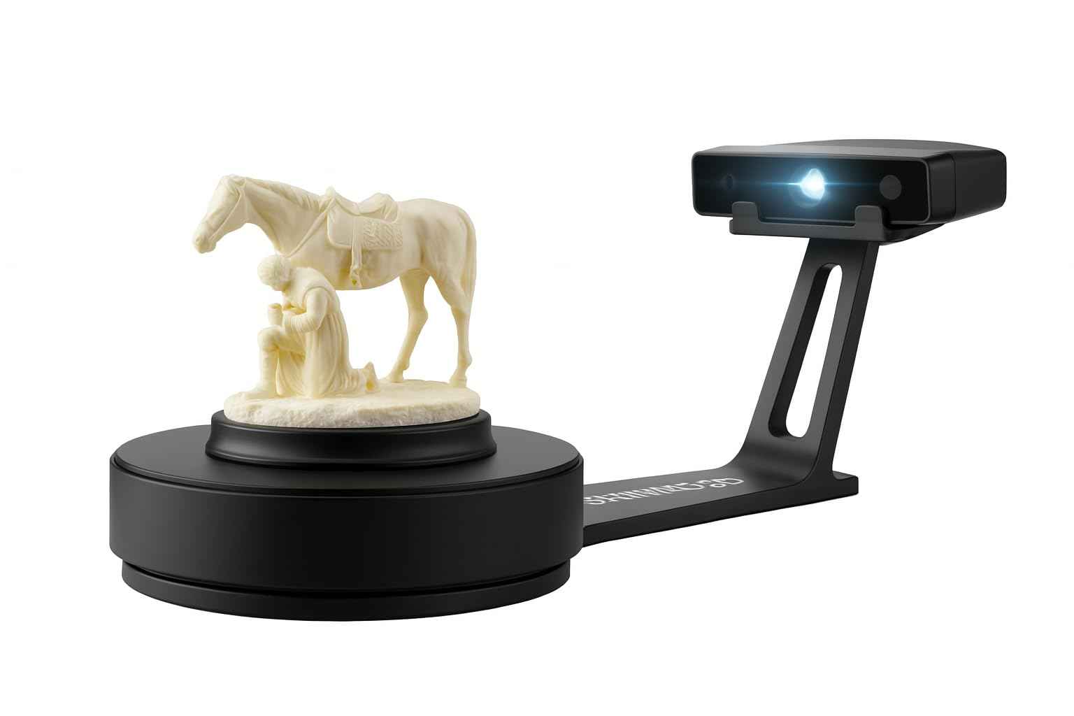
The first scanner I tested was the EinScan SE, a desktop structured-light 3D scanner from SHINING 3D. It is designed for scanning objects that are in a fixed position, after which it exports a 3D mesh suitable for 3D printing, visualization, or reverse engineering. The EinScan SE utilizes a visible white LED structure rather than a laser; this technology projects light patterns onto the object, employs cameras to observe the deformation of those patterns, and reconstructs the 3D shape. One of the main advantages of the EinScan SE is its user-friendly workflow, in contrast to the more complex process of setting up a custom photogrammetry system, where photos must be taken and processed manually, with the hope that the model will align correctly.
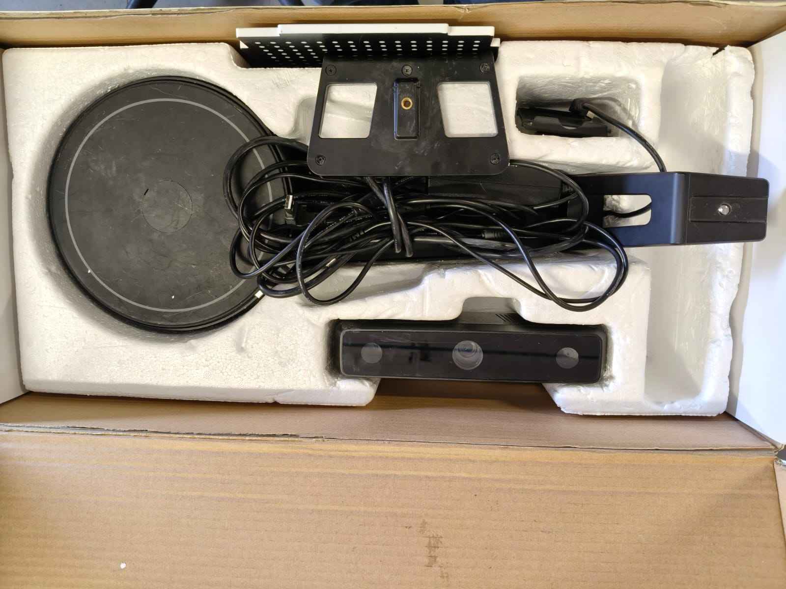
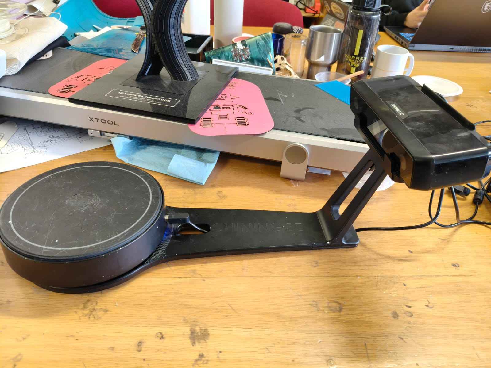
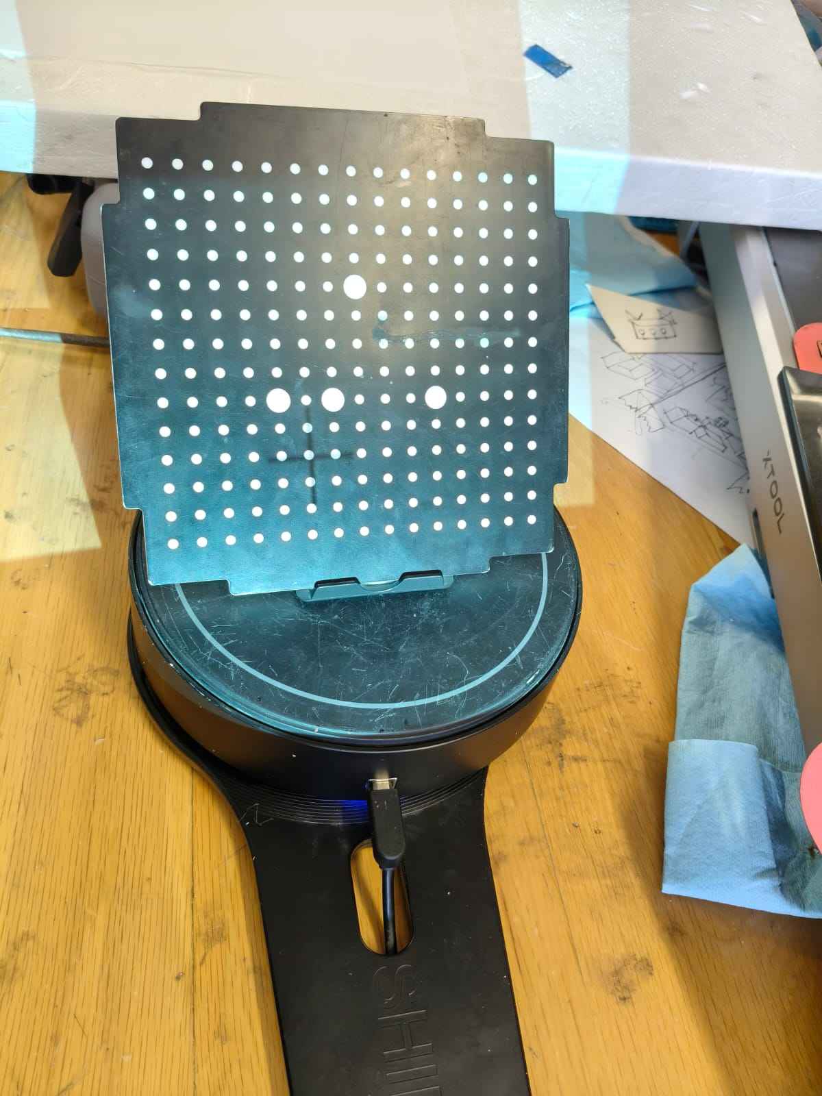
The EinnSCAN is usually stored disassembled at FabLab Ibero Puebla, so the workflow starts by unpacking and assembling its components.
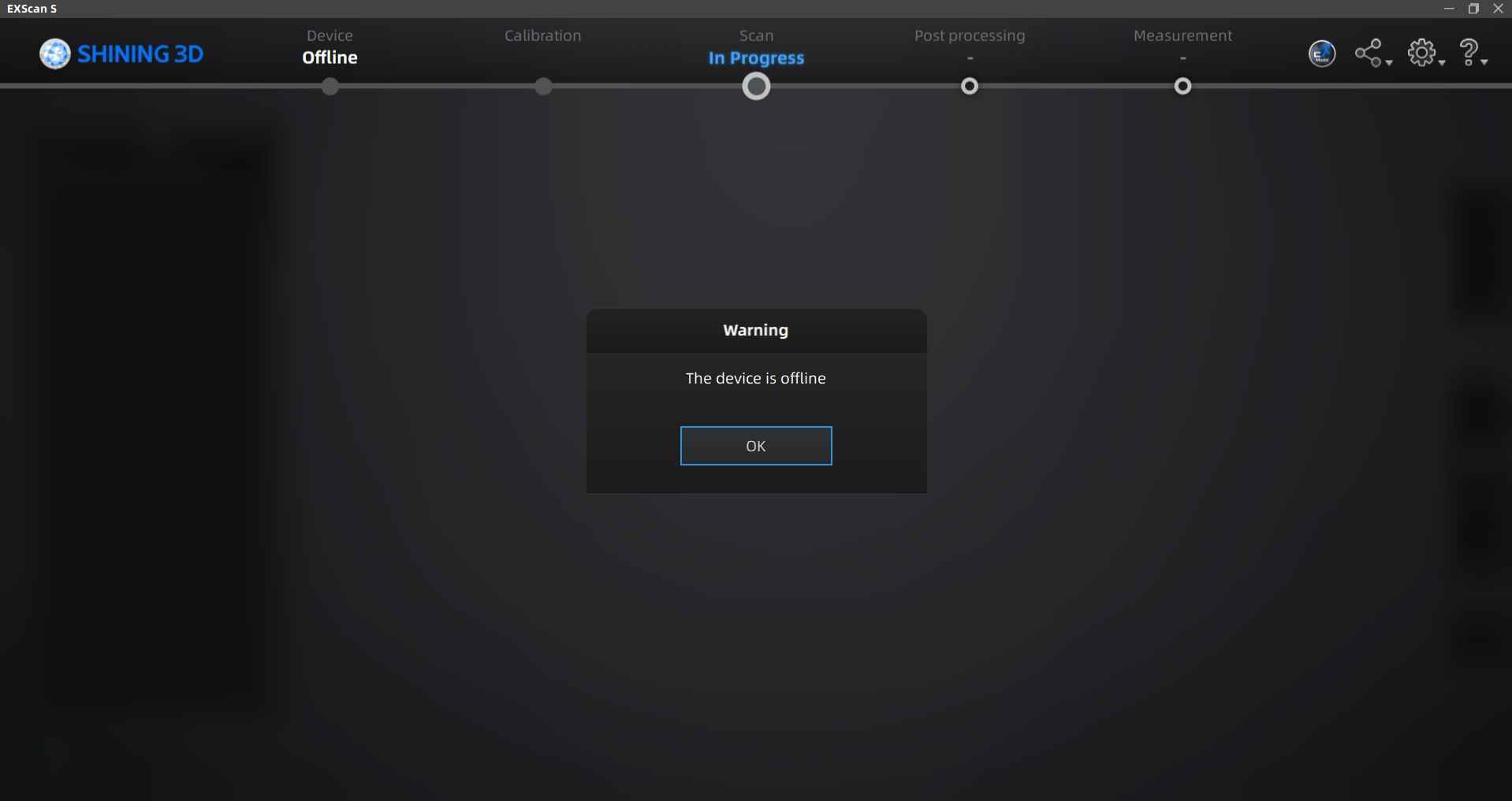
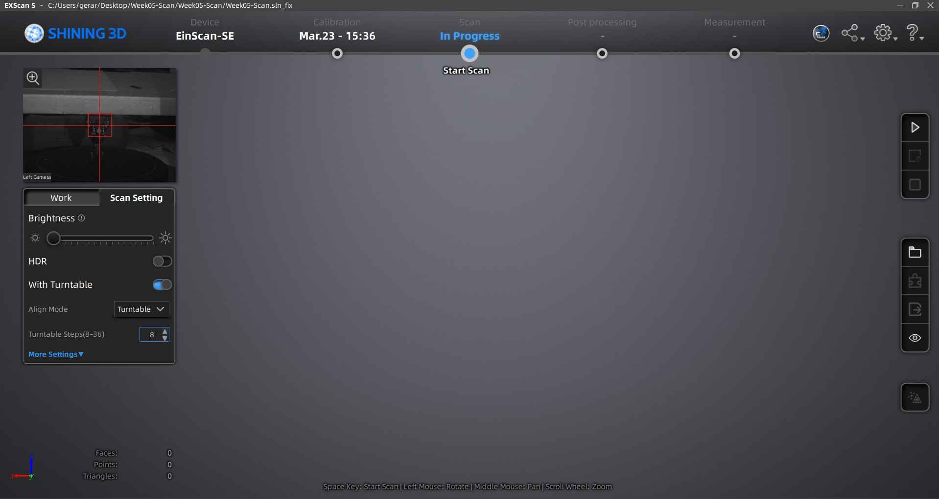
With the scanner assembled, it is now time to connect the device to the computer to start the calibration process. Please note that the EXScan 5 software requires a login; guest mode does not allow for calibration or scanning. Creating an account is free, requiring only that you provide an e-mail. If the scanner is not connected when booting the software, a screen with a message will pop up to inform the user that a scanner is not connected. After connecting the scanner, its sensor will light up and the software will show a different screen.
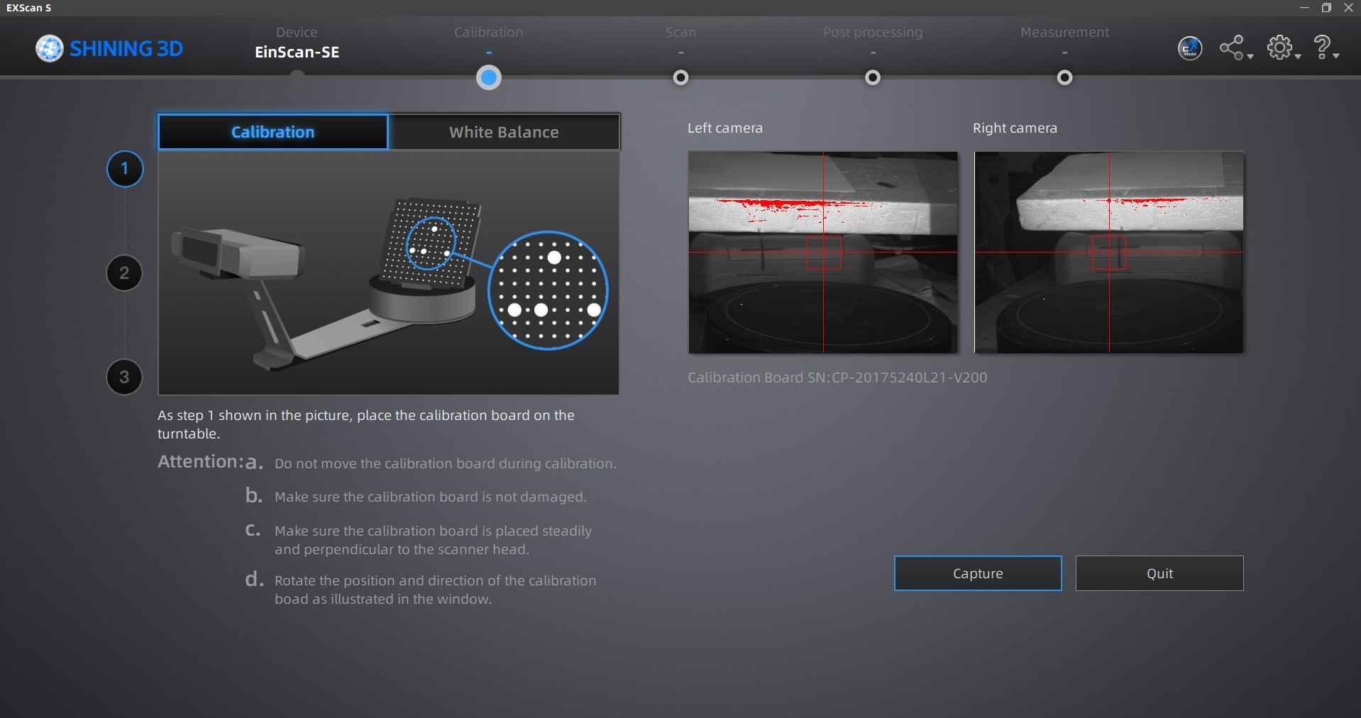
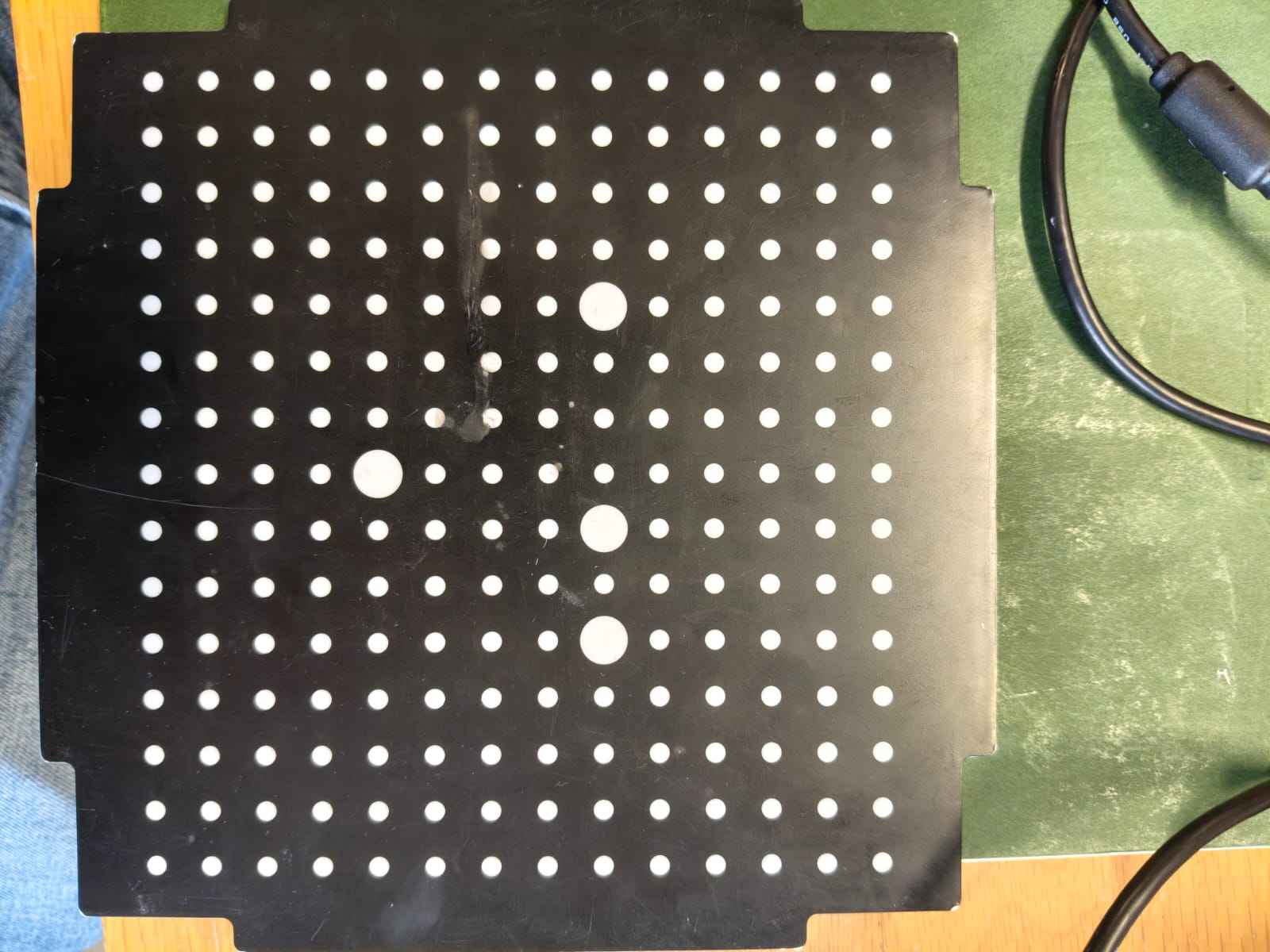
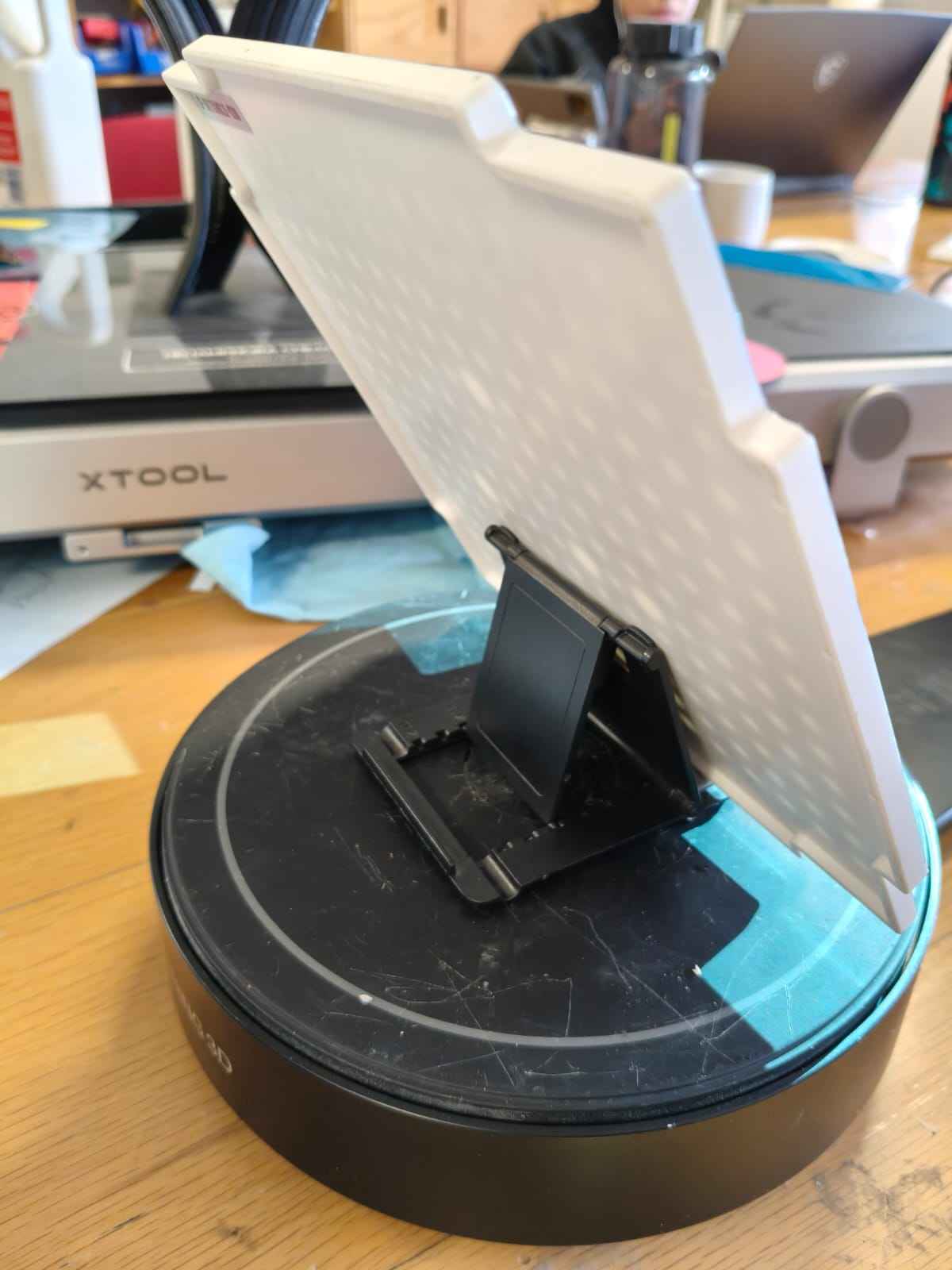
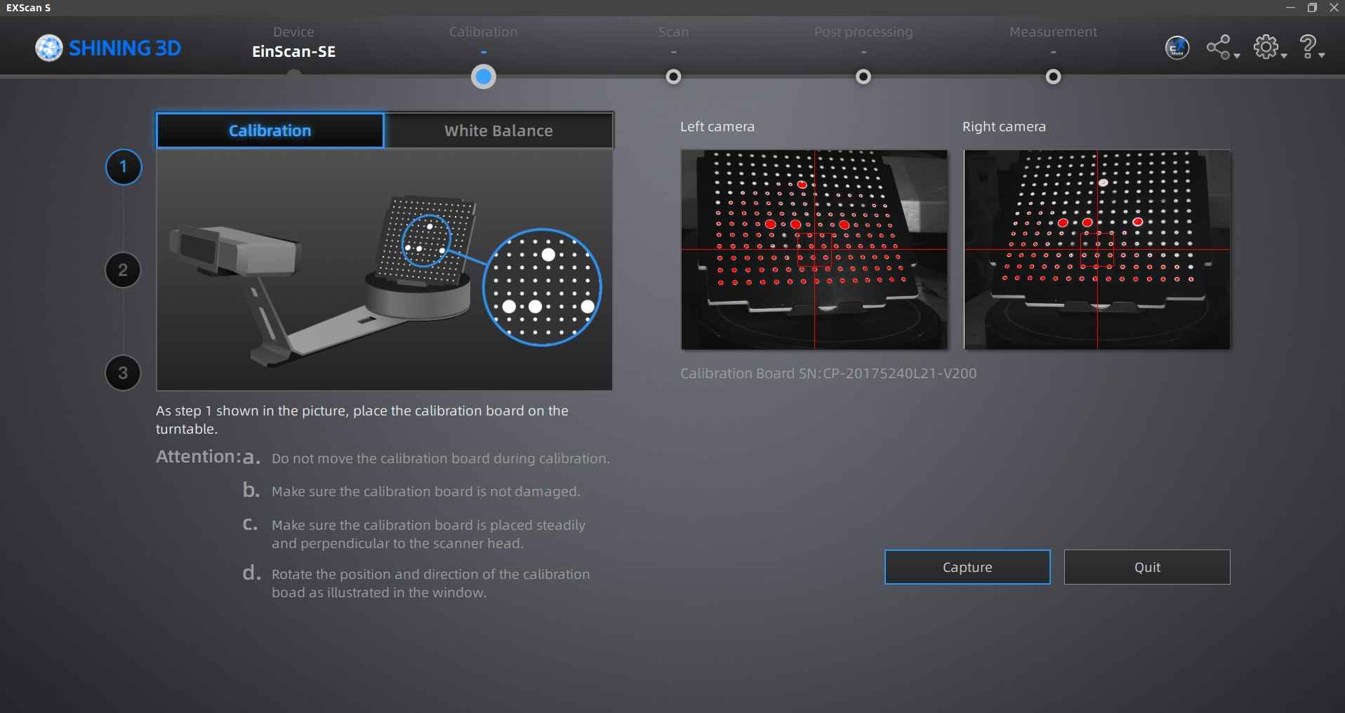
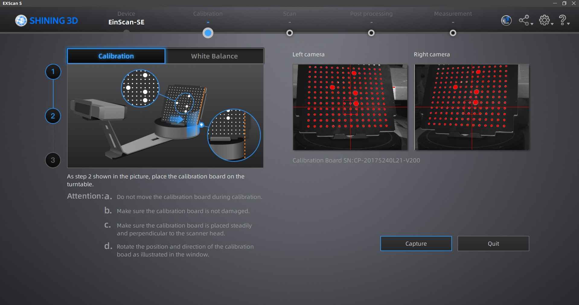
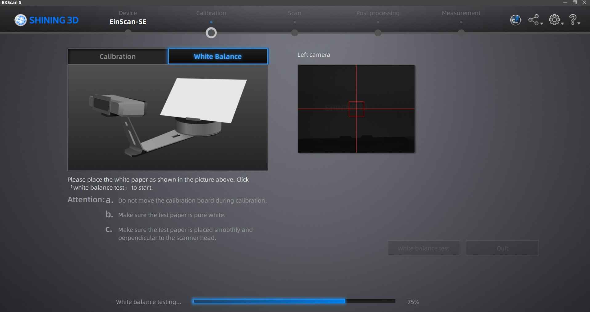
The EinSCan scanner needs calibration every time after booting; as such, its software prompts a set of instructions for calibration, which involves a special board, its stand, and a white sheet of paper. The instructions indicate that the board has to be analyzed by the scanner in three positions before proceeding with the white sheet of paper. The board's position can be adjusted by using the stand that comes included with the scanner.

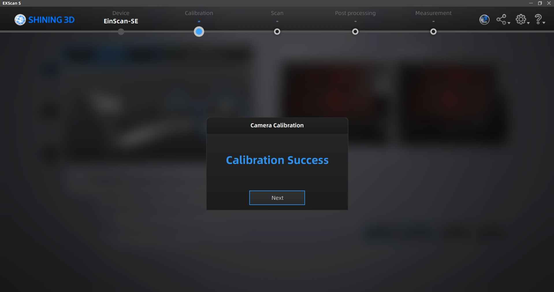
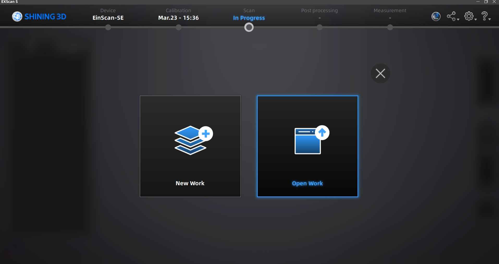
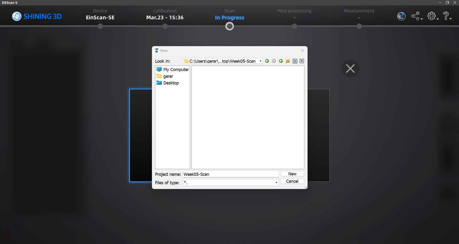
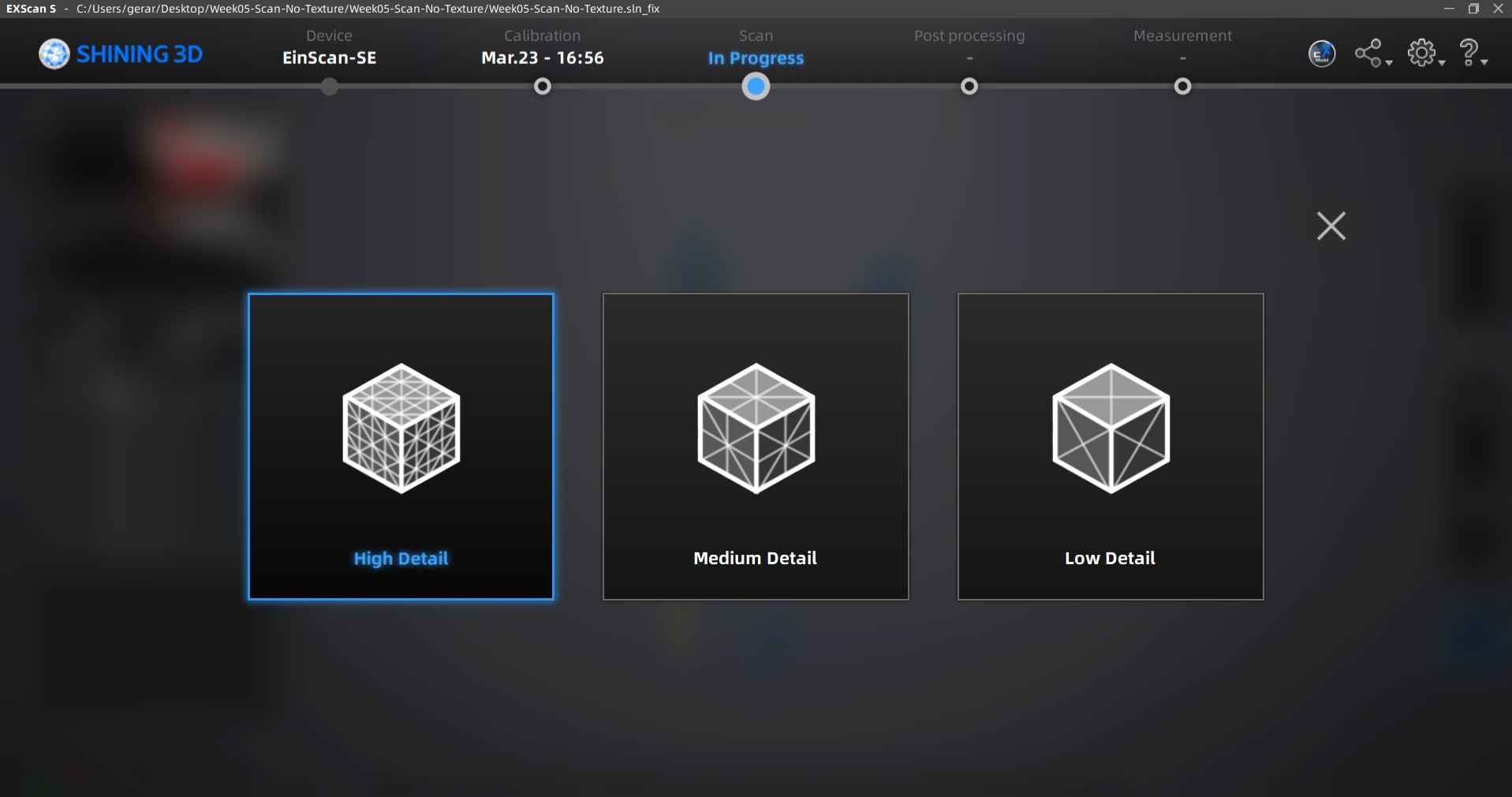
After calibrating the scanner, the software provides options to open a previous scan or initiate a new scanning project. In my situation, I opted to start a new scan.
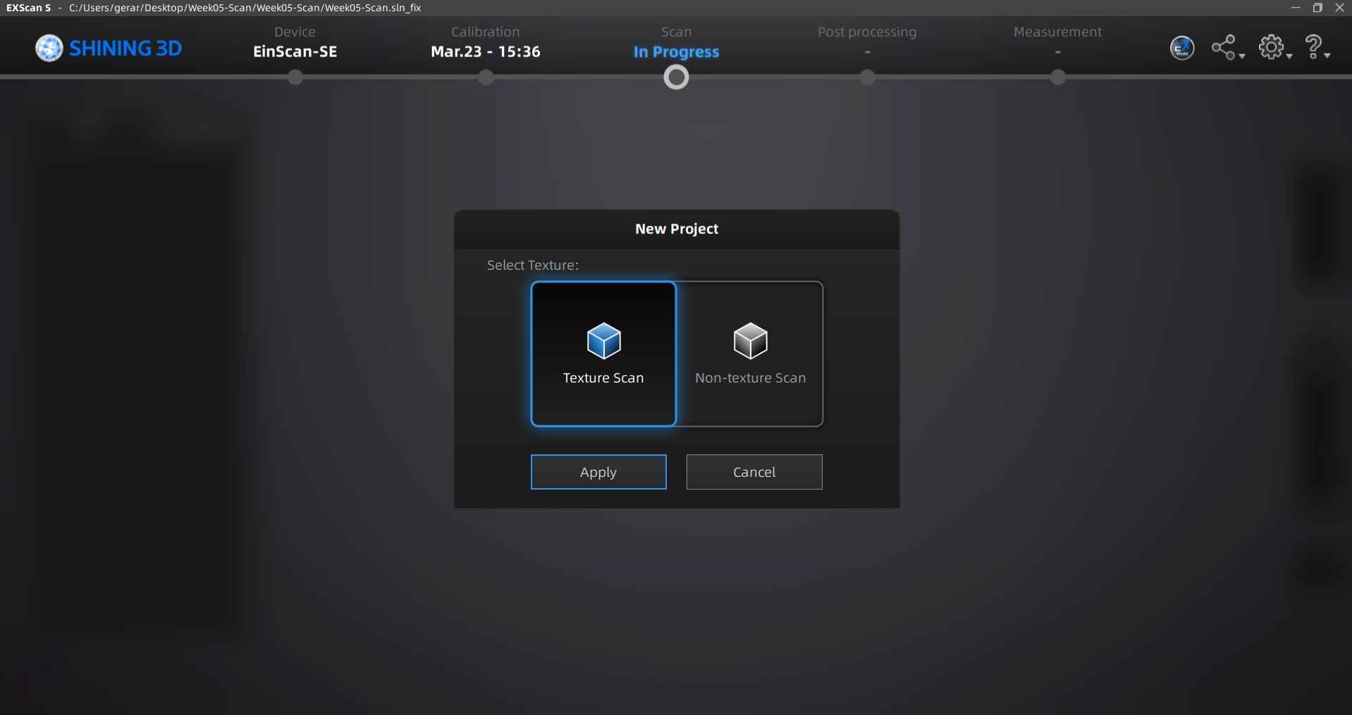
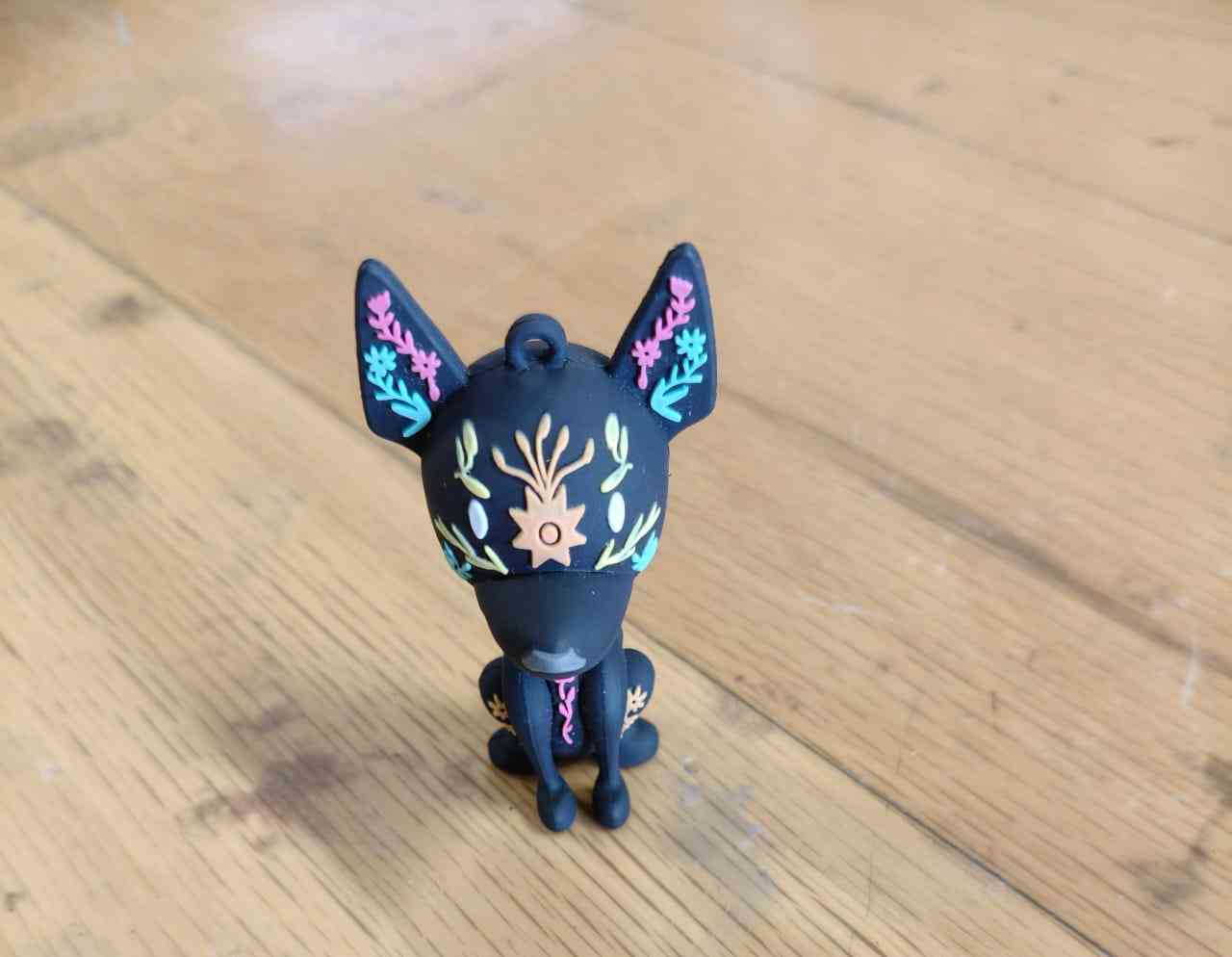
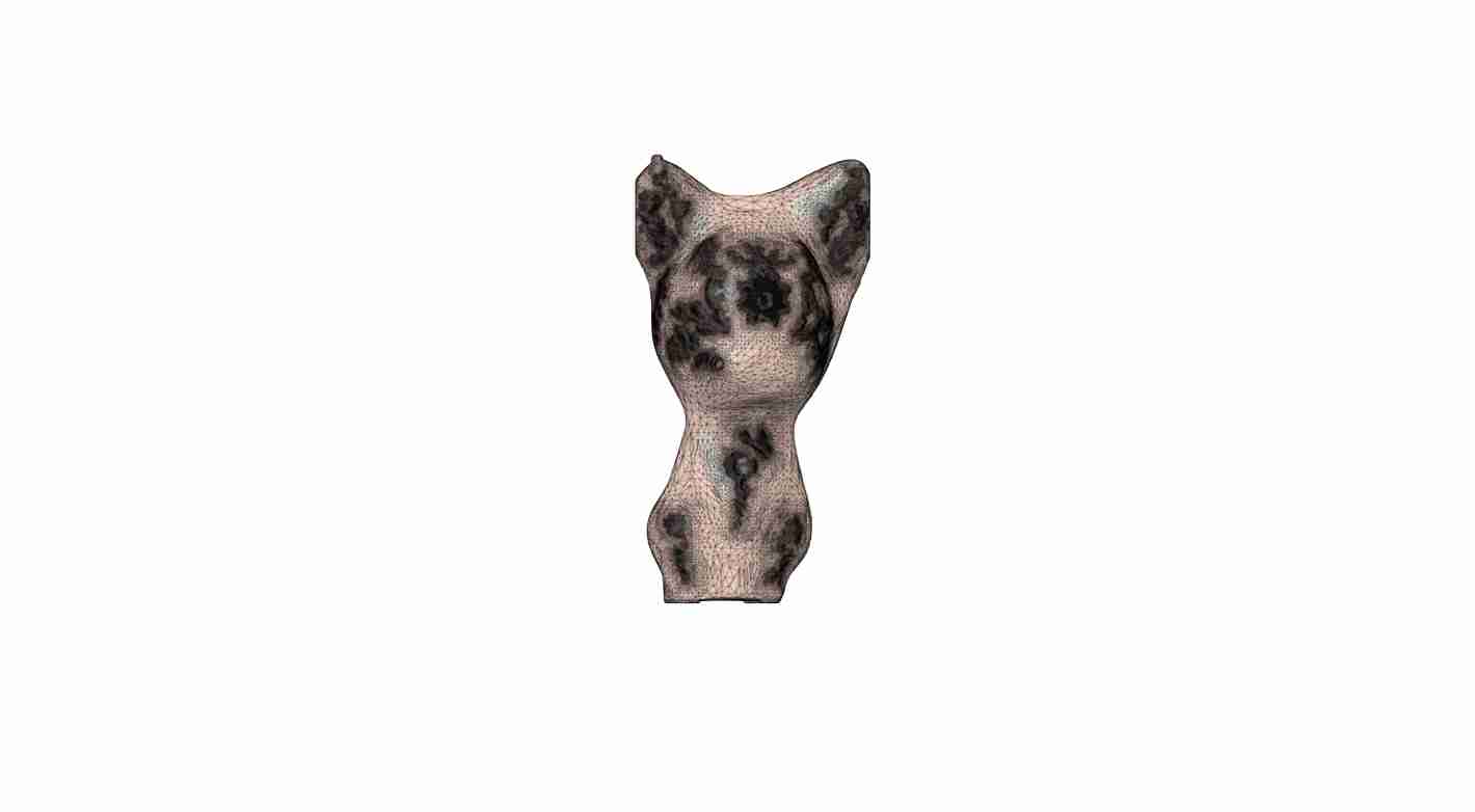
Before beginning the scanning process, the user is presented with two types of scans: one for capturing texture features etched into the object's surface and a non-texture scan for capturing only the shape of an object. I tried both scanning options. I attempted to scan a keychain shaped like a mystical xoloitzcuintli with an etched pattern. I recognized that this was a complex shape, and combined with its small size and dark color, it would give the EinScan a run for its money.
The selected object for this scan, a keychain shaped like a mystical xoloitzcuintli with an etched pattern.
After placing the keychain on top of the spinning base, I started the scanning process by pressing the play button on the right sidebar of the window.
Texture Scan
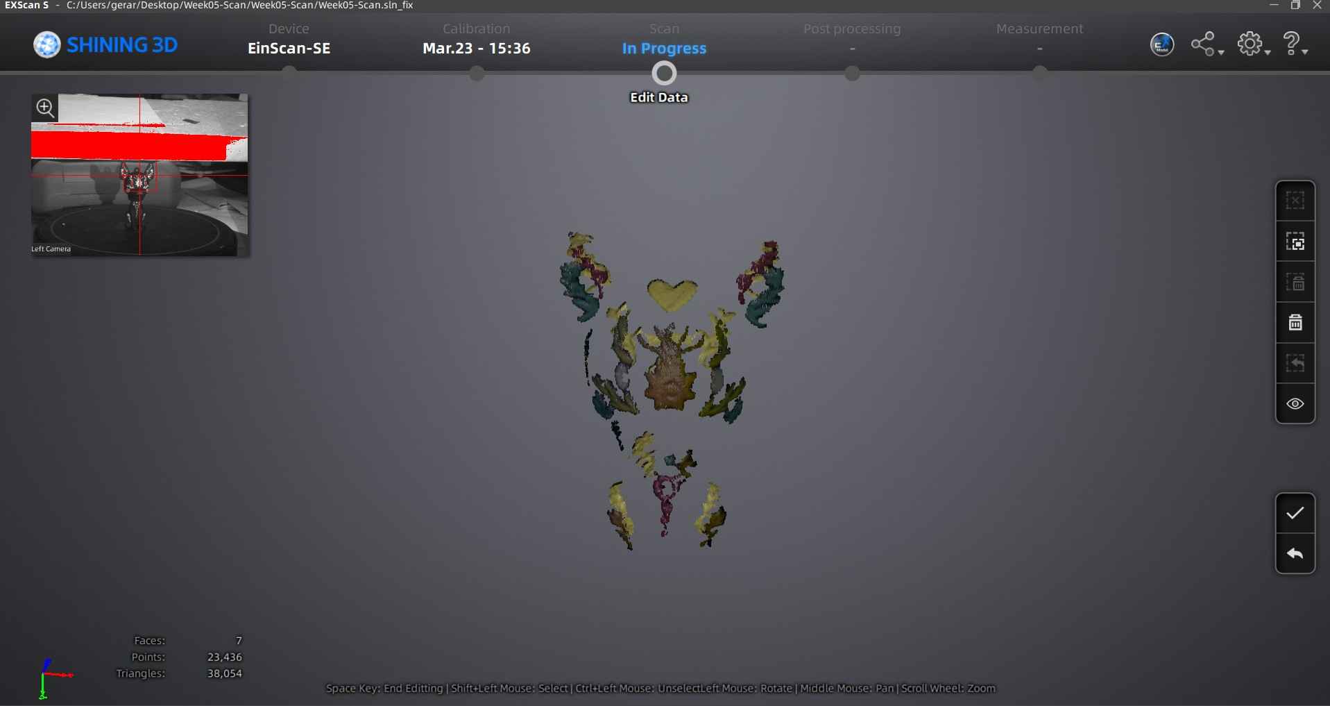
Non-texture Scan
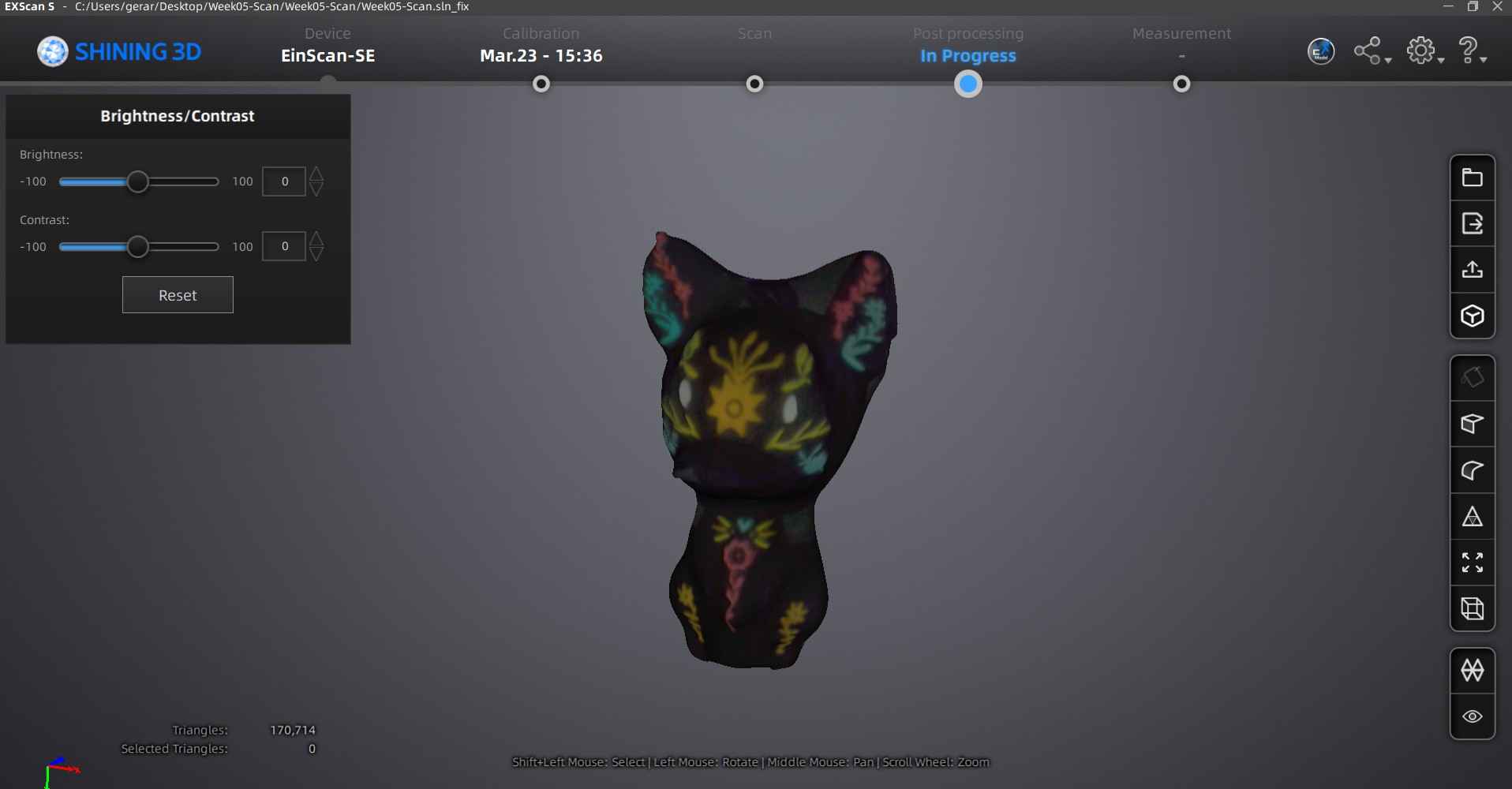
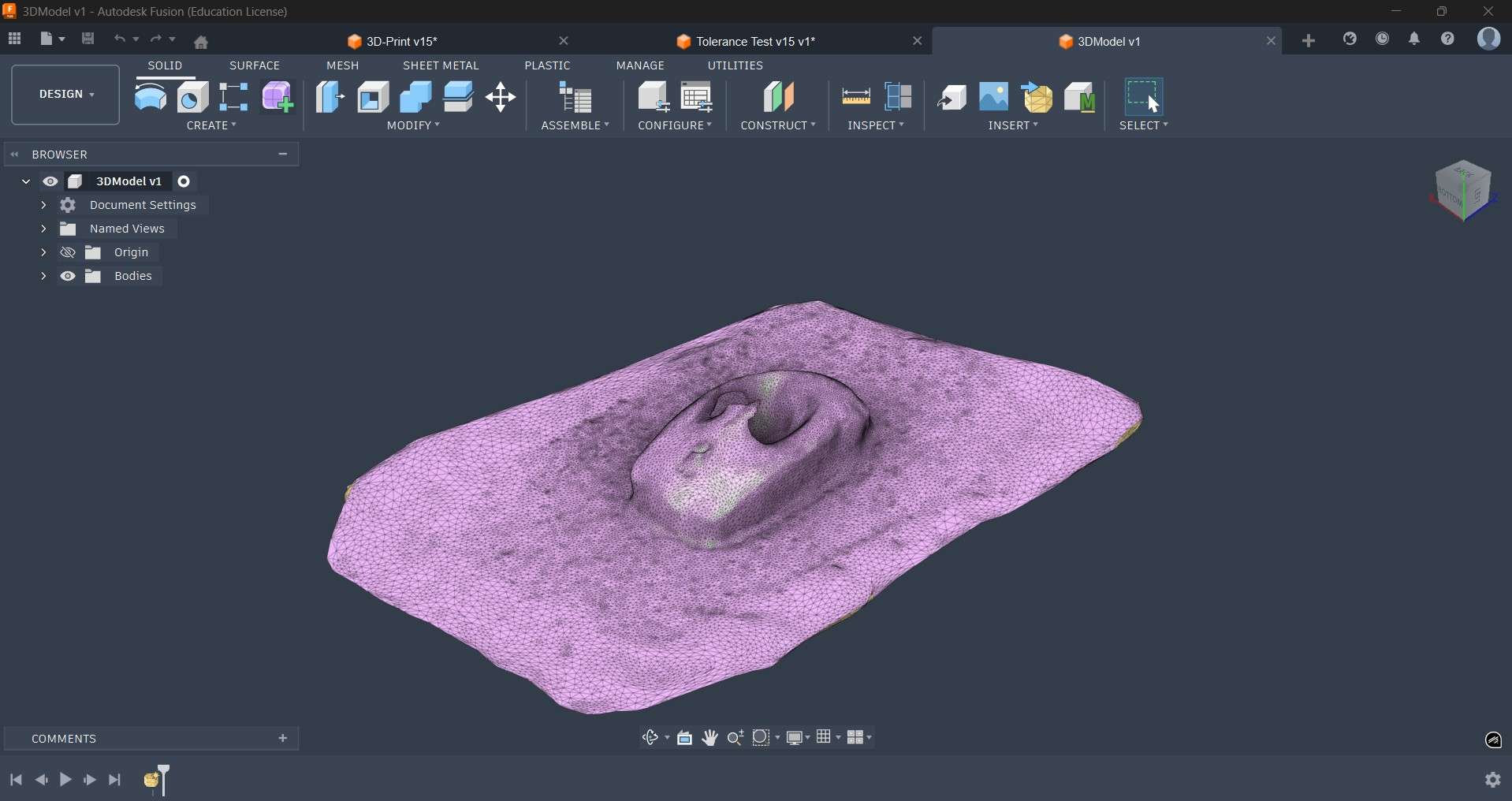
After completing the scanning process, the software provides the user with the option for exporting the generated mesh. I chose to export only the non-texture scan, which was done by pressing the second top button from the right side bar of the window.
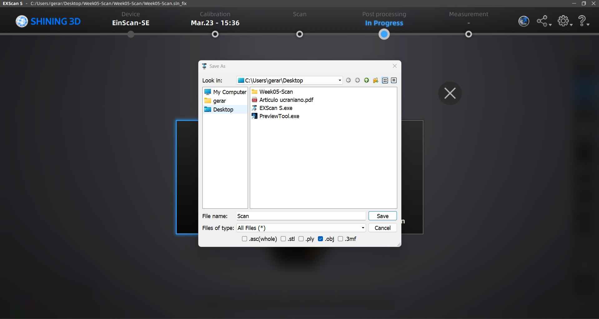
After exporting the non-texture scan, we can now further refine the resulting mesh in software like meshmixer or Fusion 360.
Creality Scan
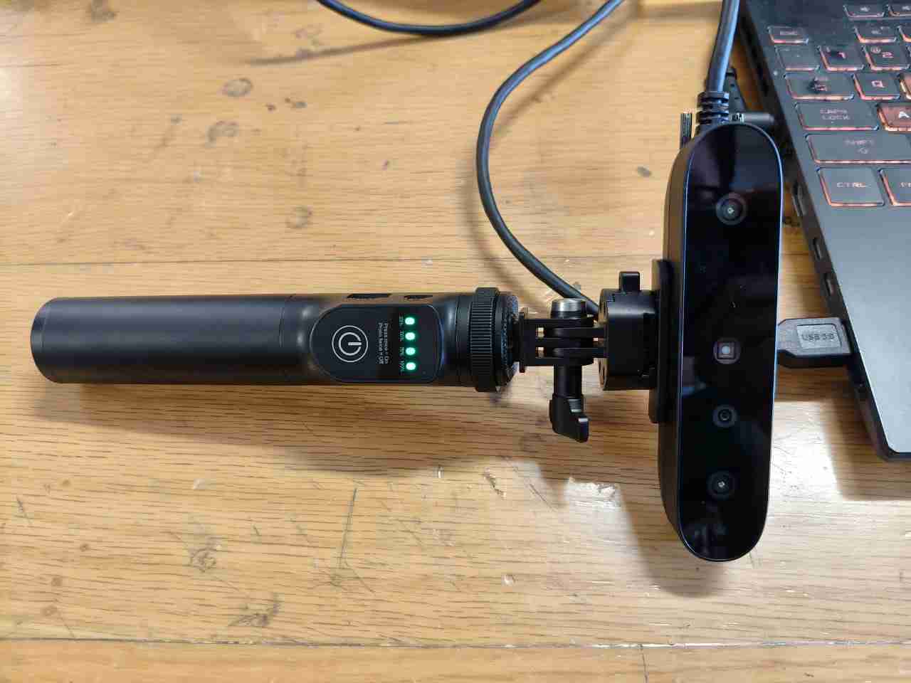
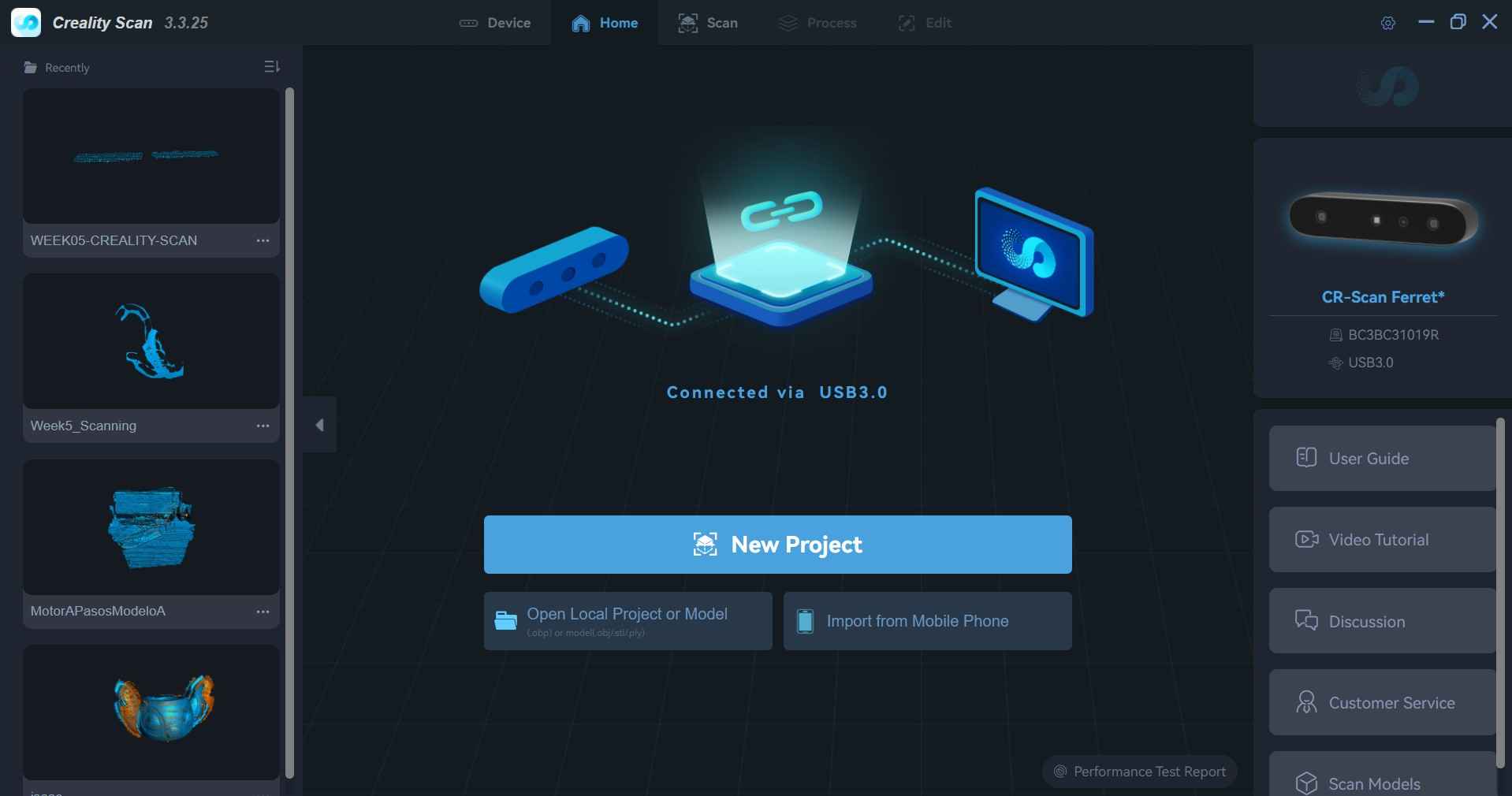
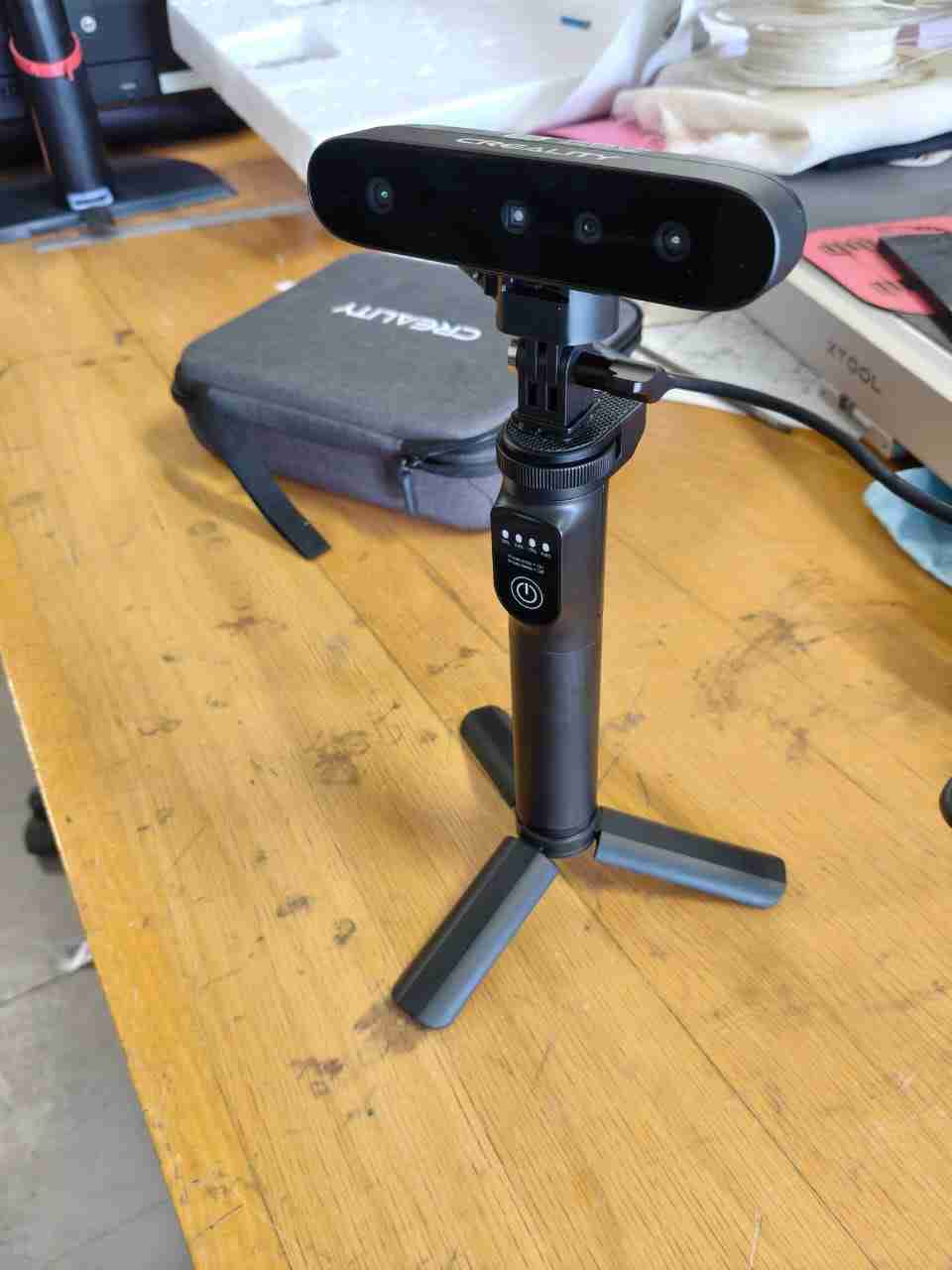
I tested another scanner for the assignment, the Creality CR-Scan Ferret Pro. This portable consumer 3D scanner is designed to capture real-world objects and convert them into data that can be processed into printable or editable 3D models. The scanner offers an accuracy of up to 0.1 mm, which is reasonable for an affordable handheld device meant for scanning geometries and subsequently refining them for 3D printing. Creality promotes features such as Wi-Fi wireless scanning, anti-shake 3D imaging, 24-bit color capture, support for scanning black and metallic objects, and compatibility with Windows, macOS, iOS, and Android. Additionally, I tested its capabilities by scanning my keychain.
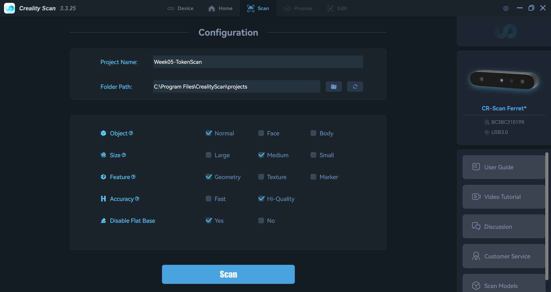
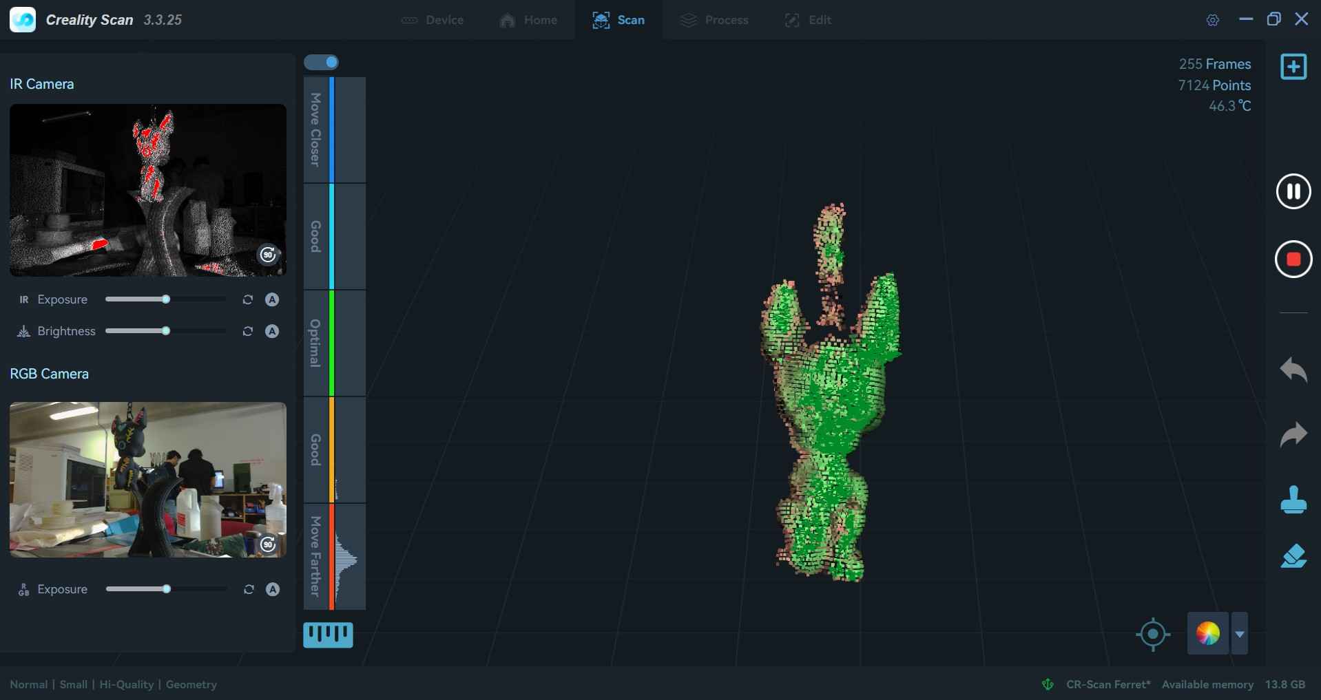
Any Creality scanner is compatible with the Creality Scan software, enabling users to access all features without the need for registration. The software requires users to provide specific information about the object they intend to scan, such as dimensions and characteristics. Once the scanner is connected to the computer, the software automatically recognizes it and presents a display showing perspectives from both the IR and RGB cameras.
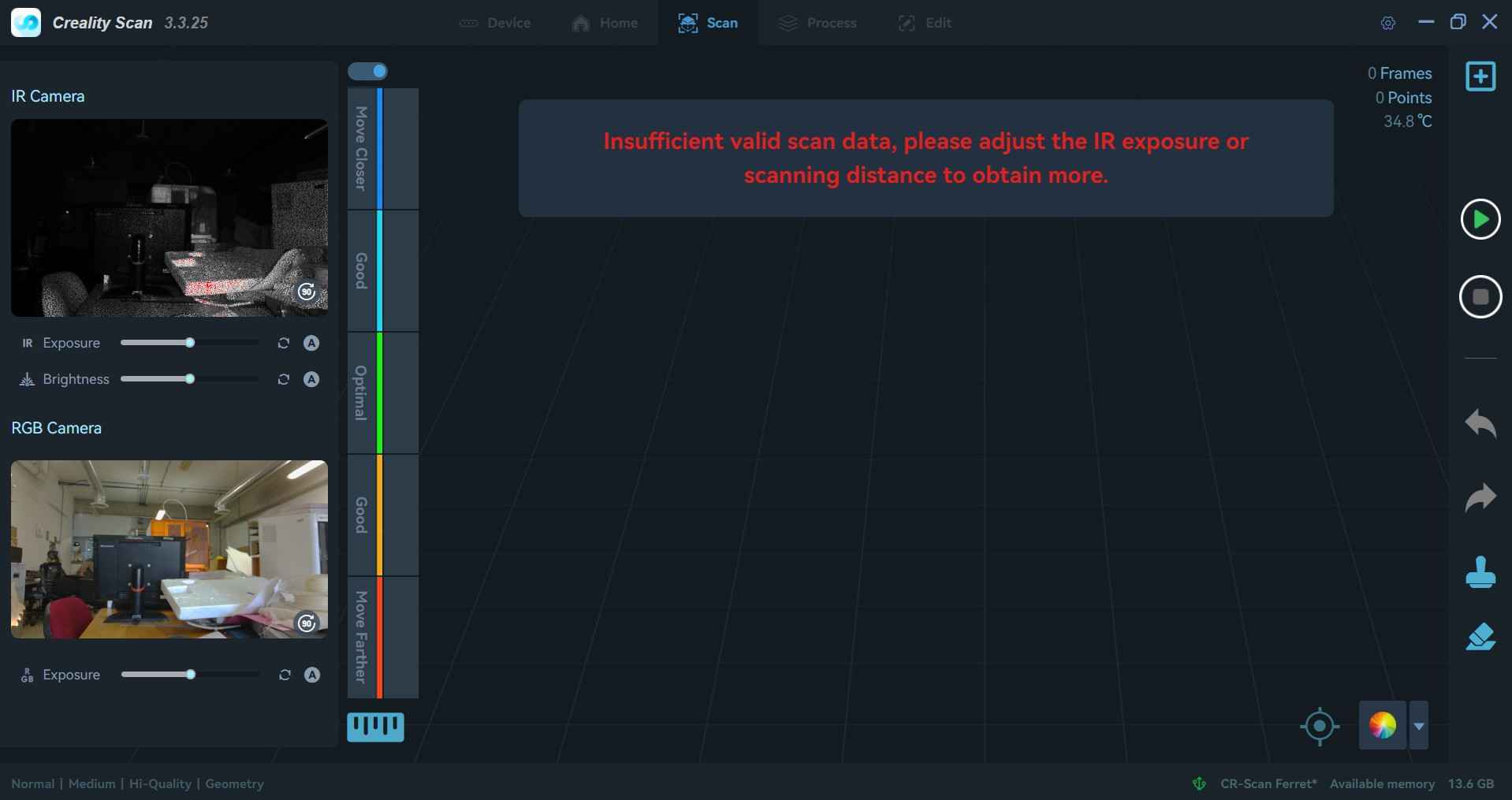
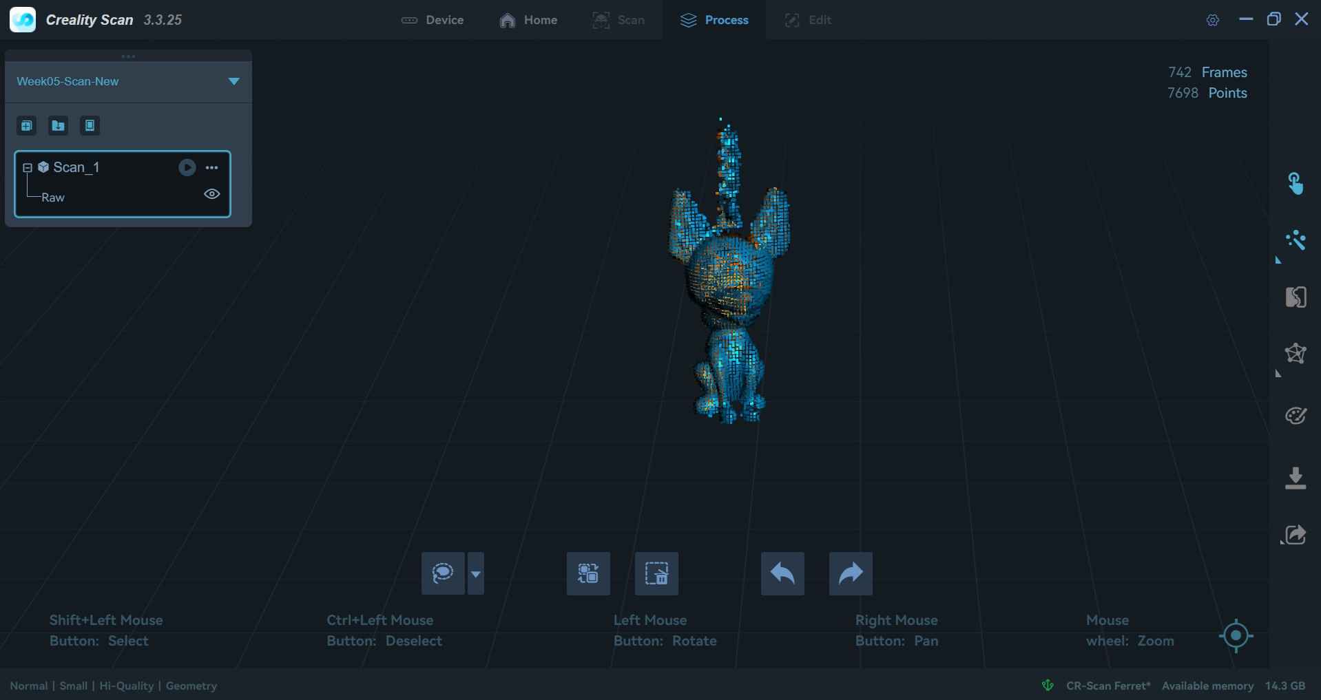
Scanning operations are started by pressing the play button located at the top of the right sidebar of the window. A status bar on the left side of the window indicates the quality of the scanned data, informing the user whether it is low or high quality. Typically, data quality can be enhanced by moving closer to or further away from the scanner or by adjusting the illumination.
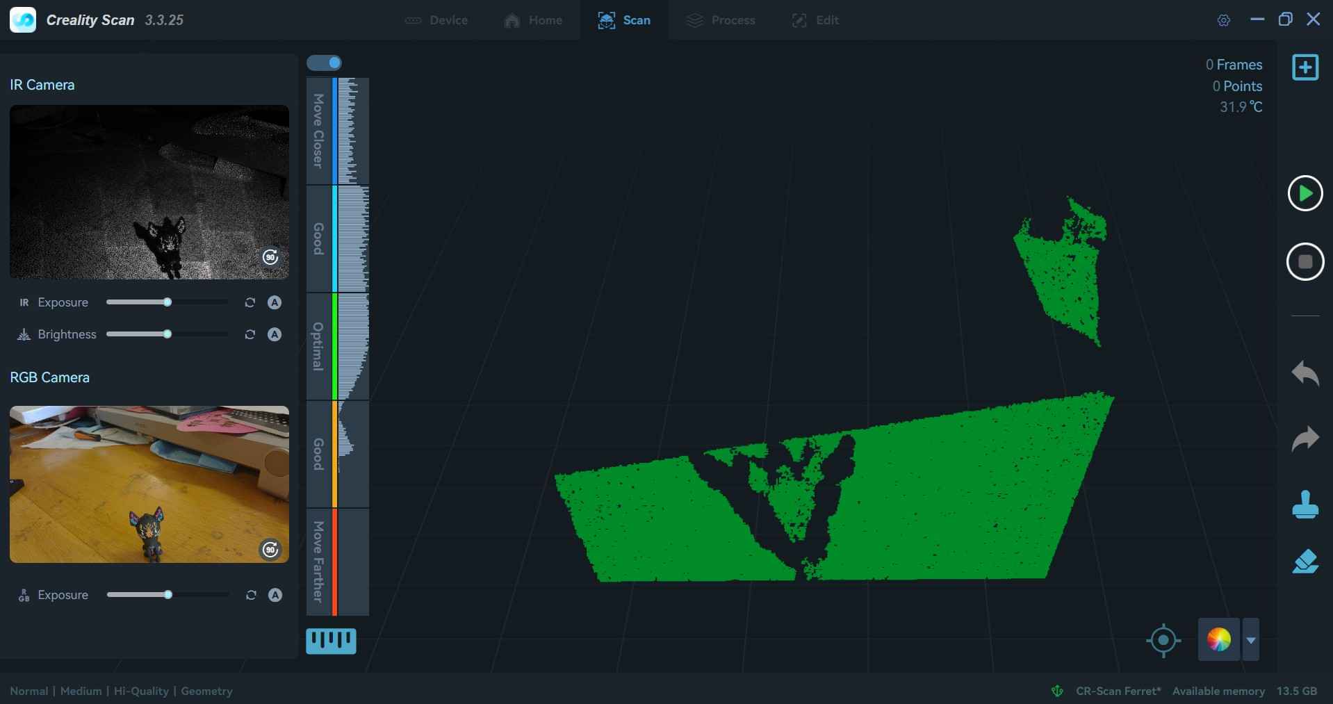
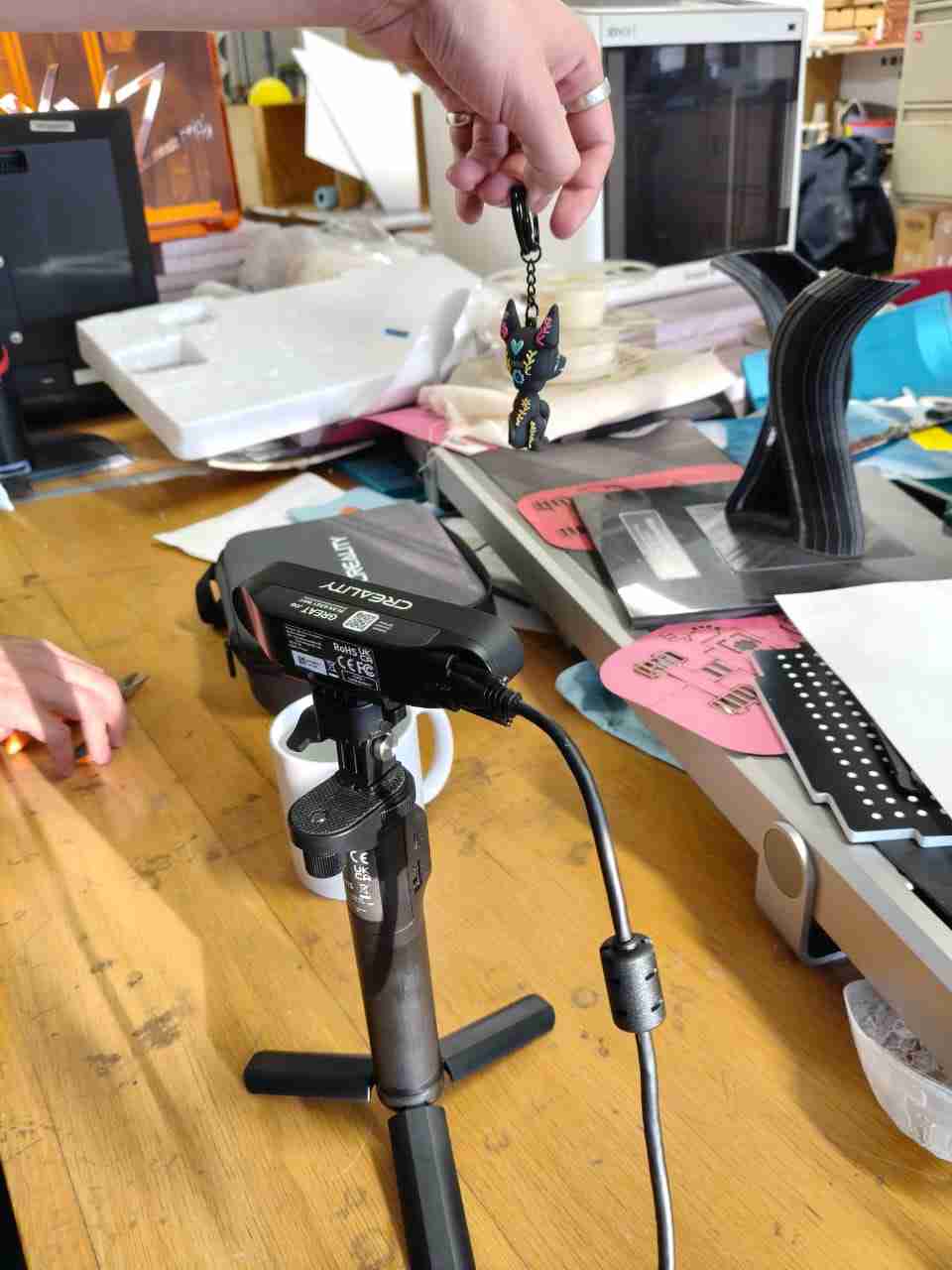
I noticed that the scanner had difficulty capturing the shape of my keychain, so I decided to mount it on a tripod. Using the tripod allowed me to better position my keychain for scanning.
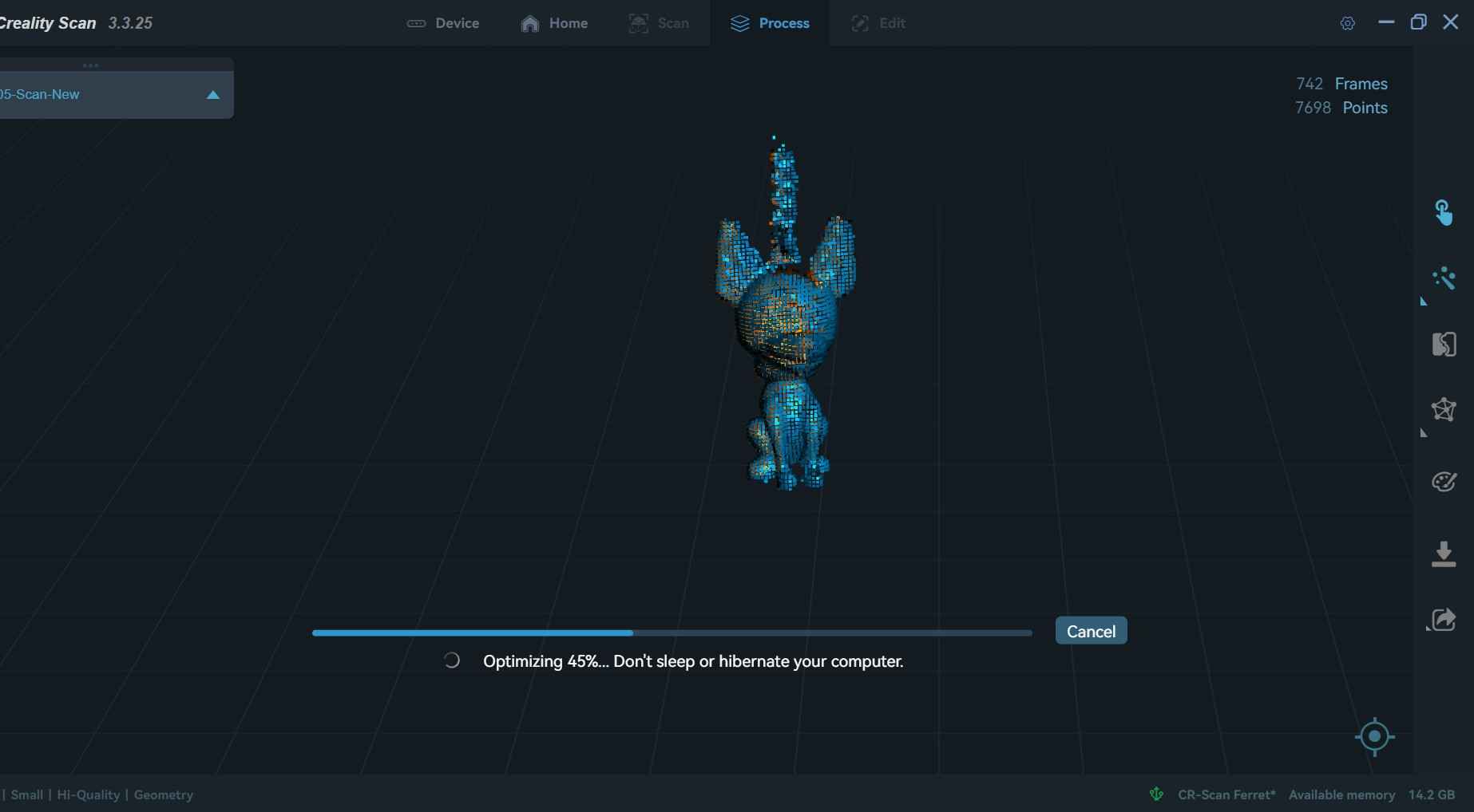
Scanning operations can be concluded by pressing the stop button, which temporarily replaces the play button during the process. Once a scanning procedure is finished, Creality Scan offers options for optimizing the mesh. Scans that capture a significant amount of data typically yield higher-fidelity replicas of an object, though they require more computational resources, which can lead to longer processing times and the need for more powerful hardware to handle the data effectively.

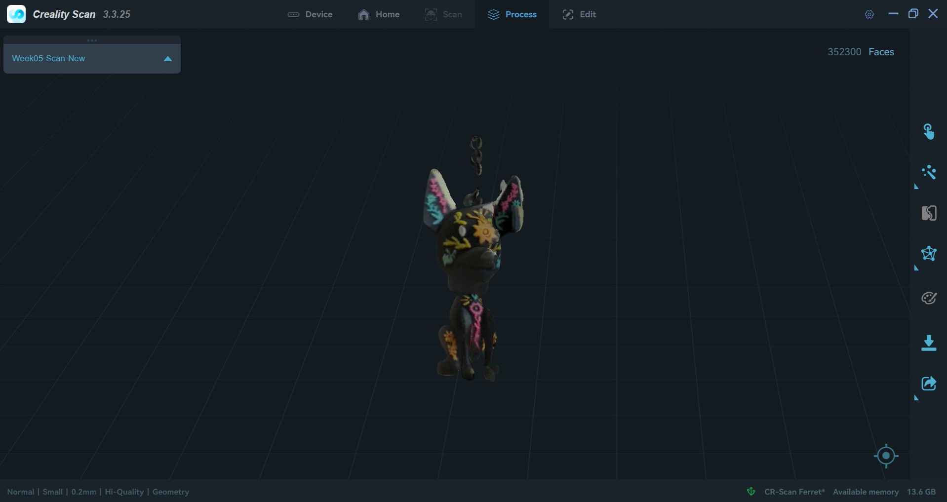
As with the EinScan software, Creality Print allows users to export meshes to other software, like Meshmixer or Fusion 360.

7. Files
Here are the downloadable files for this week:
3D model and meshReflection
Despite the stiff joints and the need to apply extra force to free the links for rotation, my 3D design worked as intended. However, I am not convinced that print-in-place joints are suitable for replacing nuts and bolts in my transforming wheel-leg design. Nevertheless, this assignment prompted me to begin evaluating how to design print-in-place mechanisms. The mesh generated from my first 3D scan could be improved by using more than 20 pictures or by utilizing a proper 3D scanner. Fortunately, I could try two scanners once I arrived at FabLab Ibero Puebla. I must admit that my expectations with both scanners may have been misplaced, as I thought they could capture shapes with pinpoint accuracy. I believe the scanners available at the FabLab could achieve that resolution when properly calibrated and handled.