Week 04 - Embedded Programming
This week, we were introduced to embedded systems programming and online simulation for code validation on specific microcontroller development boards. I chose to focus on a single microcontroller for this week's assignment. I browsed through its datasheet, wrote a code, and tested it on both an online simulator and a physical circuit. Different microcontroller architectures and development workflows of various chips were evaluated for this week's group assignment.
Work log
Completed tasks
- Browsed through the datasheet for a microcontroller.
- Wrote and tested code on an online simulator.
- Tested code on a physical circuit.
1. What is a microcontroller?
A microcontroller is an integrated circuit (IC) that includes a processor core (or cores), random-access memory (RAM), and electrically erasable programmable read-only memory (EEPROM). Because microcontrollers are lightweight and can be powered by batteries, they are well-suited for use in consumer electronics applications that require real-time signal processing, such as controlling wearables or RC vehicles. The main components of a microcontroller include:
- Central Processing Unit (CPU): Often referred to as the "brains," it serves as the core component for executing instructions and controlling operations.
- Memory: Microcontrollers contain volatile (RAM) and non-volatile (EEPROM) storage. RAM, or Random Access Memory, stores temporary data used for executing instructions. On the other hand, the EEPROM, or Erasable Programmable Read-Only Memory, stores custom programs comprised of instruction sets.
- Peripherals: The microcontroller's single-chip package combines processing capabilities, memory, input/output peripherals, timers, counters, analog-to-digital converters (ADCs), digital-to-analog converters (DACs), and communication protocols such as UART, SPI, and I2C.
While the terms "microcontroller" and "microprocessor" are often used interchangeably, they are not synonymous. A microcontroller is a complete small computer integrated onto a single chip, capable of precise operations. timing and quick responses. On the other hand, a microprocessor is mainly a CPU that requires external RAM and storage to become a functional system. Microprocessors are often found in complex applications like AI workloads or multitasking.
2. What is an embedded system?
An embedded system is a dedicated computer system developed for a specific task within a larger mechanical or electronic system. Embedded systems are often based on microcontrollers or microprocessors and include all the necessary actuators, sensors, peripherals, and firmware to carry out their assigned task.
- Dedicated purpose: Unlike general-purpose computers, embedded systems are built to perform a few specific tasks. Embedded systems within the same device can interface with each other through communication protocols to synchronize their operations.
- Real-time operation: Many embedded systems operate in real-time, meaning they must respond to inputs or events within a specific time frame. This is crucial for applications like automotive safety systems or medical devices.
- Resource constraints: Embedded systems often have limited processing power, memory, and energy resources. This requires efficient programming and optimization to ensure they function effectively within these constraints.
- Firmware: Software stored on the "brains" of a device. This software includes a set of instructions that dictate how the embedded system operates, covering input reading, output control, communication, and ensuring reliability.
3. Which microcontroller was chosen for the assignment? The RP2350!
One of the goals of my final project is to minimize development costs. In the current iteration of the prototype robot, I use a Raspberry Pi Zero 2W to receive commands and telemetry. Motion commands are then sent to a Teensy 4.1 development board, which transmits control signals to the motor drivers. However, the Teensy 4.1 costs around 50 dollars at online retailers; that price tag, along with the cost of RTK equipment, will increase overall costs. To keep costs low, I decided to look for a more affordable alternative as the basis for the motion system of my final project robot. During Embedded Programming class, Professor Gershenfeld mentioned that the RP2350 microcontroller was designed with Programmable Inputs and Outputs (PIOs), which opened new possibilities for interfacing peripherals. I wanted to know more about the PIOs, so I decided to focus my weekly assignment on the RP2350 and its Raspberry Pi Pico 2W development board, which costs around 10 dollars.
The RP2350 is a 32-bit dual-core microcontroller unit (MCU) developed by Raspberry Pi as the successor of the RP2040. The RP2350 is usually found on Raspberry Pi Pico 2 development boards or XIAO RP2350 boards. Key features include:
- CPU: The RP2350 CPU can operate with either two Arm Cortex-M33 cores or two Hazard3 RISC-V cores, both running at a frequency of 150 MHz. It is possible to configure a mixed setup of Arm and RISC-V processors; however, doing so necessitates the use of two separate program images.
- Memory: Memory consists of 520 KB of on-chip SRAM organized into ten independent banks. It supports up to 16 MB of external QSPI flash or PSRAM through a dedicated QSPI bus. Additionally, an optional second chip select allows for access to another 16 MB of flash or PSRAM.
- Peripherals: Two UART interfaces, two SPI controllers, two I2C controllers, twenty-four PWM channels, and four or eight ADC channels depending on the variant. Additionally, there is one USB 1.1 controller and PHY, supporting both host and device modes.
- Security features: Optional boot signing is implemented through the on-chip mask ROM, utilizing a key fingerprint stored in the OTP. There is protected OTP storage available for an optional boot decryption key. Global bus filtering is applied based on Arm or RISC-V security and privilege levels. Peripherals, GPIOs, and DMA channels are assigned to specific security domains individually. Hardware mitigations are in place to protect against fault injection attacks. A hardware SHA-256 accelerator is included.
- Programmable Input/OutputThree high-performance Programmable I/O (PIO) co-processors, with a total of twelve independent state machines, support software-defined interfacing, with little or no CPU overhead. Each can independently execute sequential programs to manipulate GPIOs and transfer data. PIO state machines are specialized for I/O, with a focus on determinism, precise timing, and close integration with fixed-function hardware.
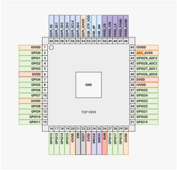
This is the RP2350 shown in the datasheet provided by Raspberry Pi.
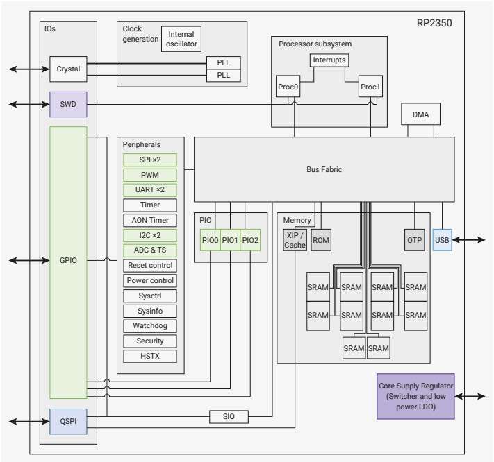
System overview of the RP2350 chip. Dual Cortex-M33 or Hazard3 processors access RP2350’s memory and peripherals via the AHB (Advanced High-performance Bus) and APB (Advanced Peripheral Bus) fabric.
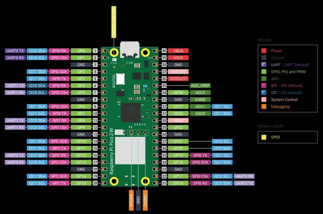
This diagram shows the pinout from the Raspberry Pi Pico 2W development board.
4. Programming languages
Before proceeding with programming, it is important to note that there are two types of programming languages, compiled and interpreted.
In a compiled language, source code is translated before execution into machine code or into a low-level binary format. This translation results in optimized code that runs faster at runtime because the CPU executes native instructions directly. Compiled code usually has more predictable timing and less overhead at runtime. These characteristics enable control systems to operate deterministically under real-time constraints. Additionally, compiled code is usually memory-efficient, which allows its deployment on small microcontrollers with limited RAM/flash. Compiled code usually runs faster. However, compiled languages have slower iteration cycles; the need for compilers also results in heavy toolchains and more responsibility for low-level details. Typical examples of compiled languages include C/C++, Rust (embedded), and TinyGo (embedded).
In an interpreted language, the code is executed by an interpreter or virtual machine firmware that runs on the hardware. Code is executed immediately, debugging is often simpler, and interactive workflows are common. This quick prototyping and development speed results in rapid validation of hardware connections and codes. However, interpreters add overhead per instruction and consume flash and RAM, leaving fewer resources available for coding. Memory is managed automatically; when objects are created (strings, lists, dicts, temporary variables, etc.), they occupy RAM. When those objects are no longer needed, the system frees that memory. Garbage collection, interpreter overhead, and runtime scheduling can introduce jitter. Nevertheless, an interpreted language is useful for prototyping, learning, or timing performance when needs are moderate. Examples of compiled languages include MicroPython and CircuitPython.
For this assignment, I chose to write code using MicroPython, as it includes a module that provides a ready-made, high-level way to write PIO programs.
5. Setting up the simulation
For this assignment, my initial goal was to use the Wokwi online platform to simulate a system based on a Raspberry Pi Pico 2W. This system would receive signals from three push buttons and a potentiometer to determine the direction and speed of a DC motor. Such a system could serve as the foundation for my final project. However, Wokwi does not support models for simulating DC motors and drivers controlled by a Raspberry Pi Pico 2W. Nevertheless, the platform contains other elements that could act as stand-ins for the simulation.
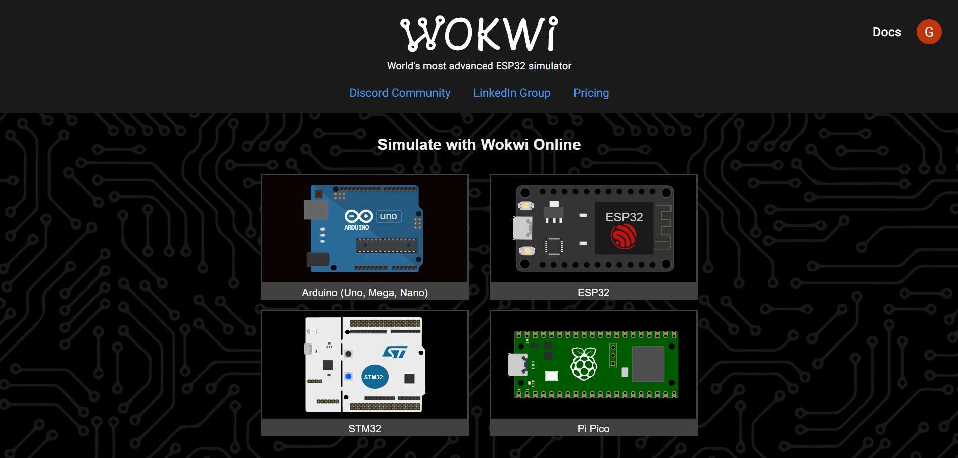
Wokwi is an online platform that allows simulating microcontroller-based projects. It provides a user-friendly interface for designing, testing, and debugging projects. You can access the platform through a web browser, and to save projects, you need to create an account. With an account already set up, the next step is to create a new project and select a development board. In my case, the choice is the Pi Pico.
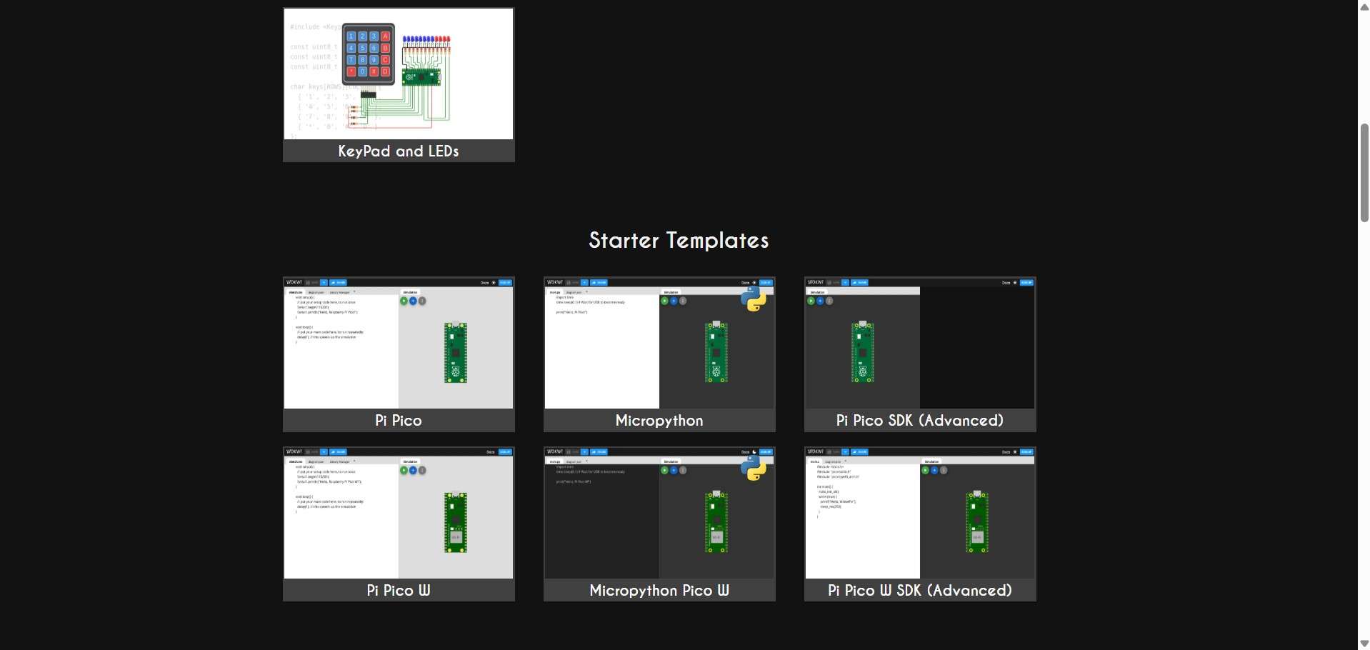
Once you select a development board, Wokwi presents a menu with customizable "Starter Templates" for project creation. I chose the Micropython Pico W.
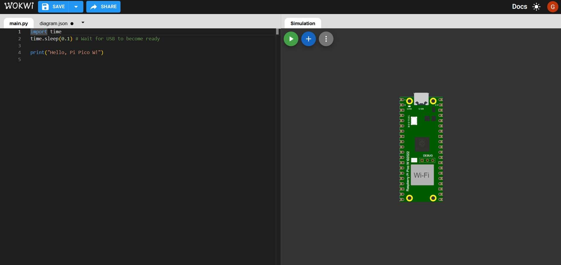
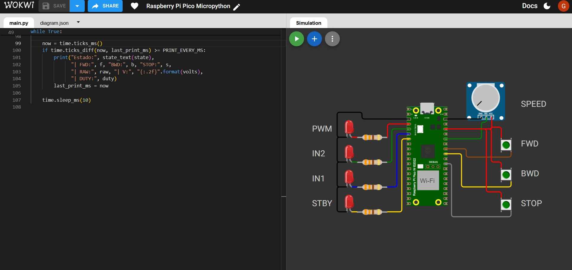
After choosing a template, the screen will show two main sections and an upper bar. The bar contains project management options for saving, naming, and sharing projects. The left section contains an interface similar to an IDE, which will be used to write code. The code will control the simulated electronic components on the right side.
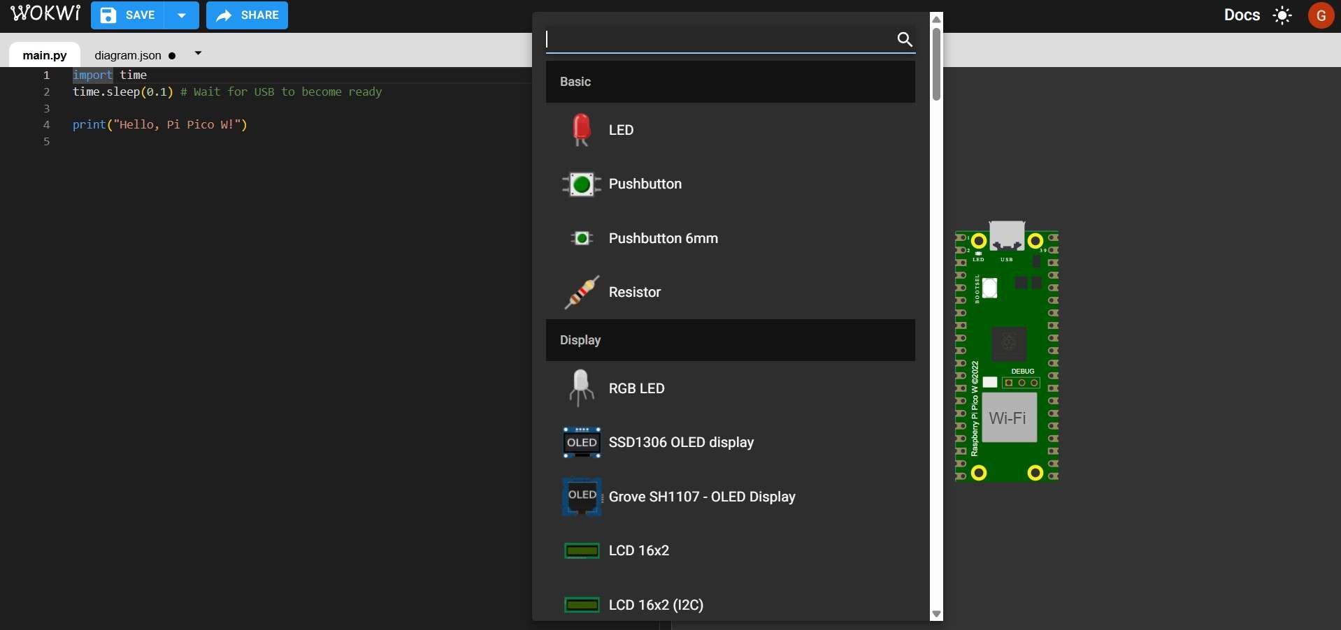
Additional electronic components can be added by clicking on the blue circle with a "+"; this will show a menu from which parts can be sorted out by typing their names in the search bar.
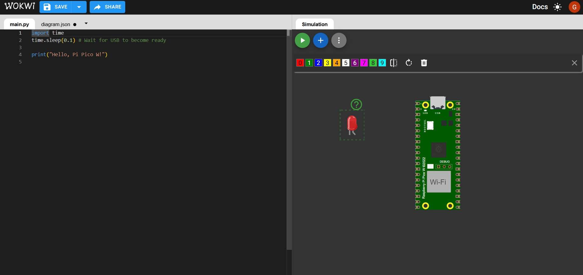
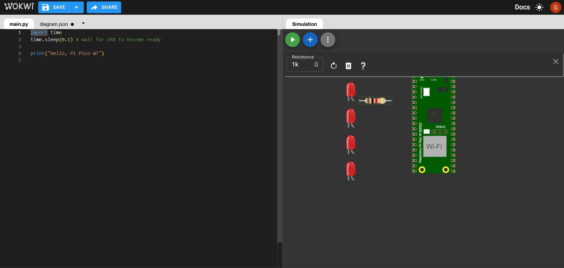
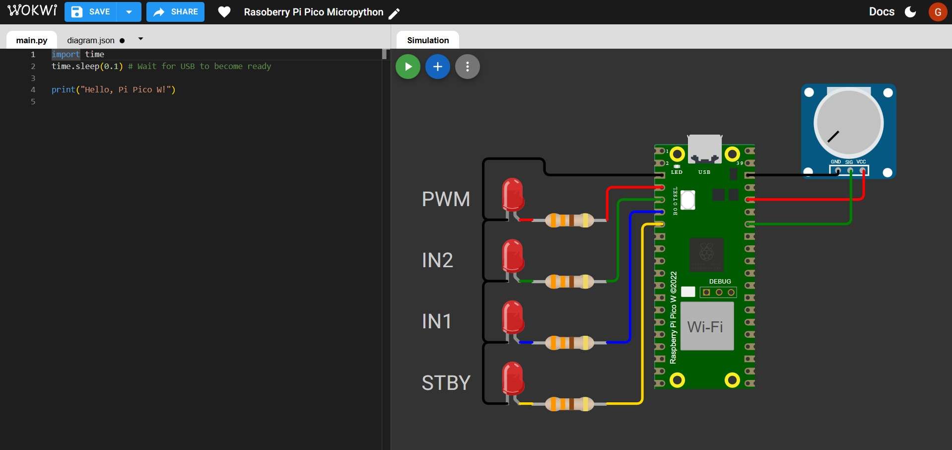
For this simulation, I will place 4 LEDs as stand-ins for the inputs of a TB6612FNG motor driver. To control one motor with this driver, the setup requires 2 digital inputs for direction, 1 PWM output for speed, and a single digital input to enable or disable the driver.Each component will show a green question mark when hovered over with the mouse cursor. Clicking this symbol will display a page with notes about that particular component, including some tutorials.
Even though Wokwi does not require resistors to protect LEDs as a physical circuit would, I chose to include them as part of my simulation. The value of each resistor can be changed by clicking on it and typing a different value on the "Resistance" bar. Band colors will change accordingly. I chose to use 330 ohms, which are common for red LEDs.
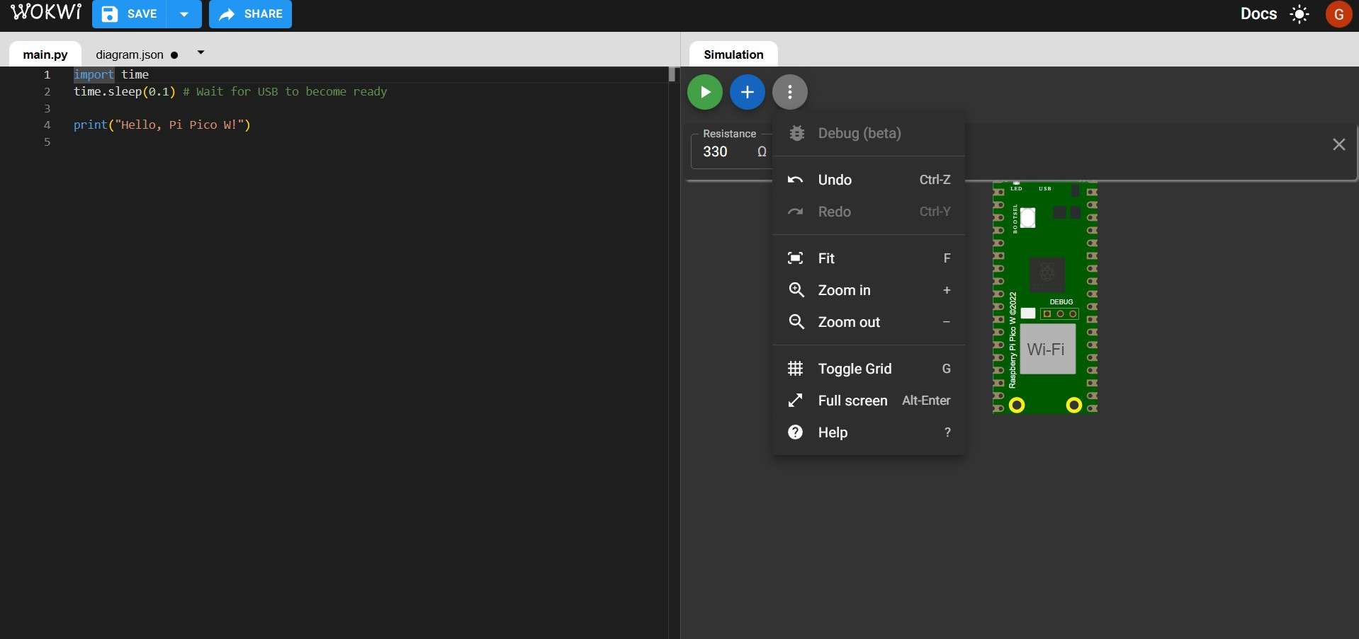
The simulation screen of the project can also show a grid by clicking on the gray button with a vertical dotted line. By selecting the "Toggle Grid" option, the grid can be hidden or shown for better component alignment.
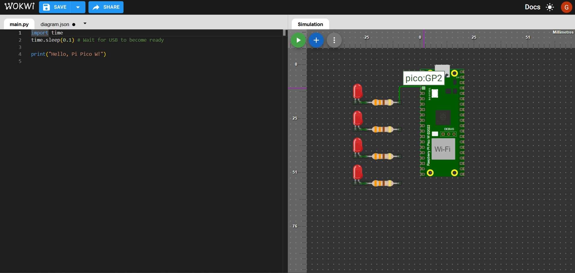
Components can be connected by clicking on one terminal and selecting another terminal as an endpoint for the connection. A textbox will show the name of the terminal over which the mouse is currently hovering while connecting components. The color of each connection can be managed individually; I highly recommend choosing different colors for signals, power, and ground.
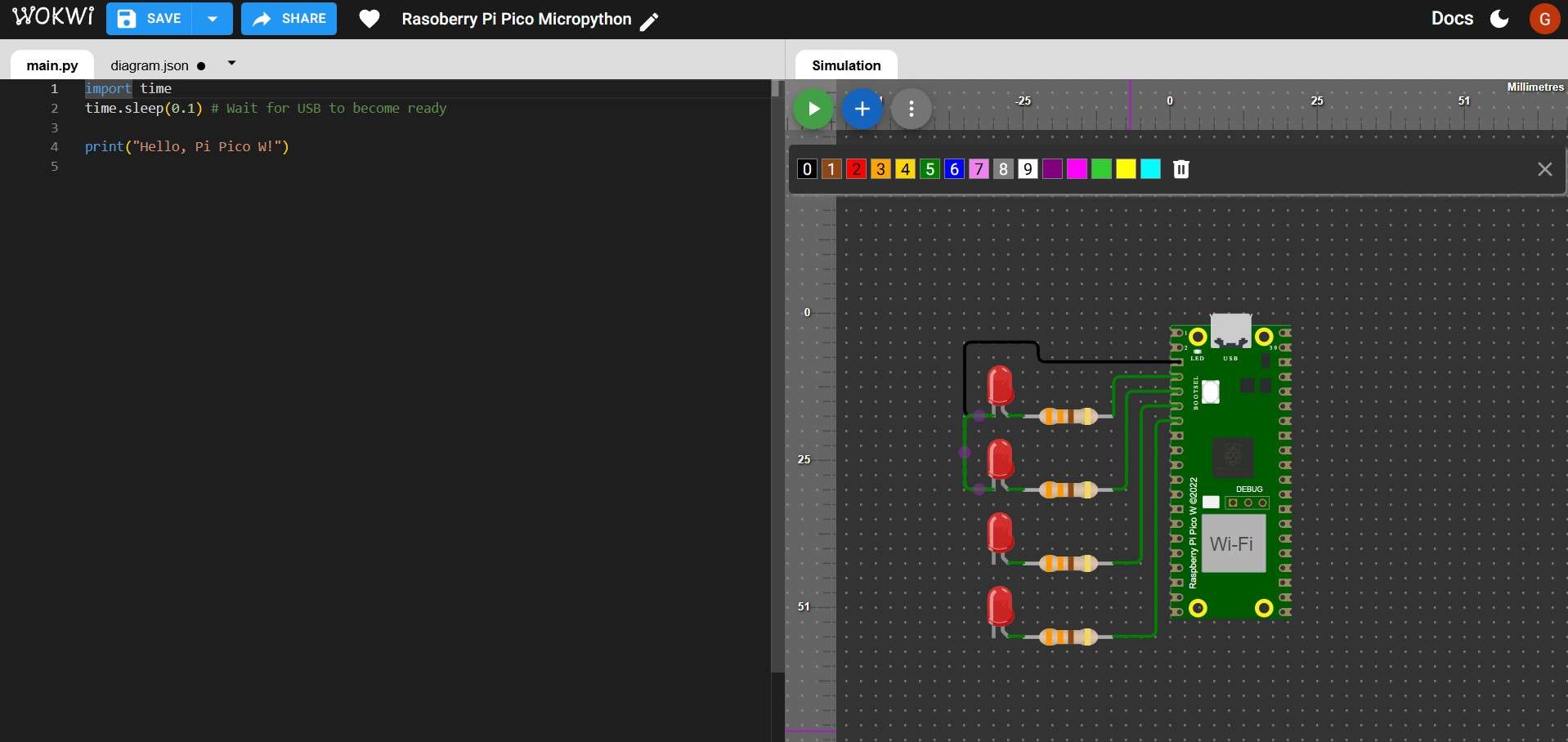
Color selection for connections.
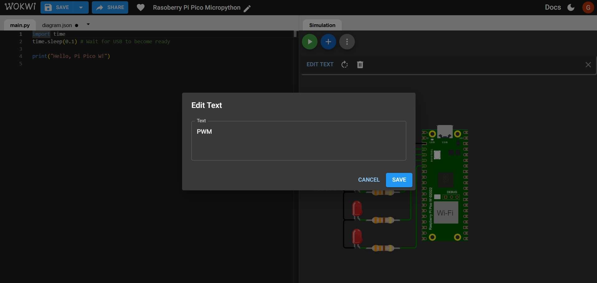
Wokwi lets users place labels next to components for better identification. In my case, this will be useful for identifying which LED corresponds to a pin on a TB6612FNG driver.
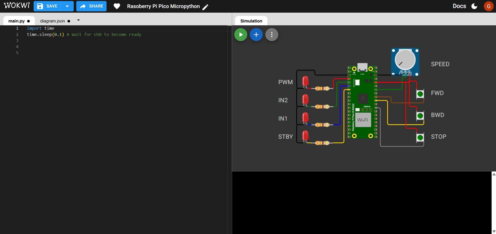
Wokwi offers the option to simulate an analog input using either a knob potentiometer or a slide potentiometer. I opted for the knob potentiometer. Although the current simulation model is not fully developed—since it does not require users to connect the GND and VCC terminals—I decided to include these connections. This choice is based on Wokwi’s plans to update its potentiometer models in the future.
To complete the circuit, 3 push buttons are included. These buttons do not require a pull-down resistor, as the Raspberry Pi Pico already has those resistors internally.
6. Programming
Given Wokwi's previously mentioned limitations, the simulated system will begin operating with all LEDs turned off. The knob adjusts the voltage that controls motor speed, indicated by the brightness of the PWM LED. If the potentiometer's value exceeds the deadband, pressing either the FWD or BWD button will activate the PWM LED, with brightness corresponding to the voltage provided by the potentiometer. Pressing one of these buttons will light up either the IN2 or IN1 LED, indicating the motor is moving backward or forward. The STBY LED will remain on as long as the "motor" is active, regardless of which button is pressed. The motor will stop when the STP button is pressed or when the potentiometer voltage drops to zero. The speed voltage can be adjusted in real-time during the simulation; however, to change direction, the motor must first be stopped before it can start spinning in the opposite direction.This passage will explain how to write a code that fulfills these requirements.
6.1 Libraries
The first lines of code are used to import the necessary libraries.
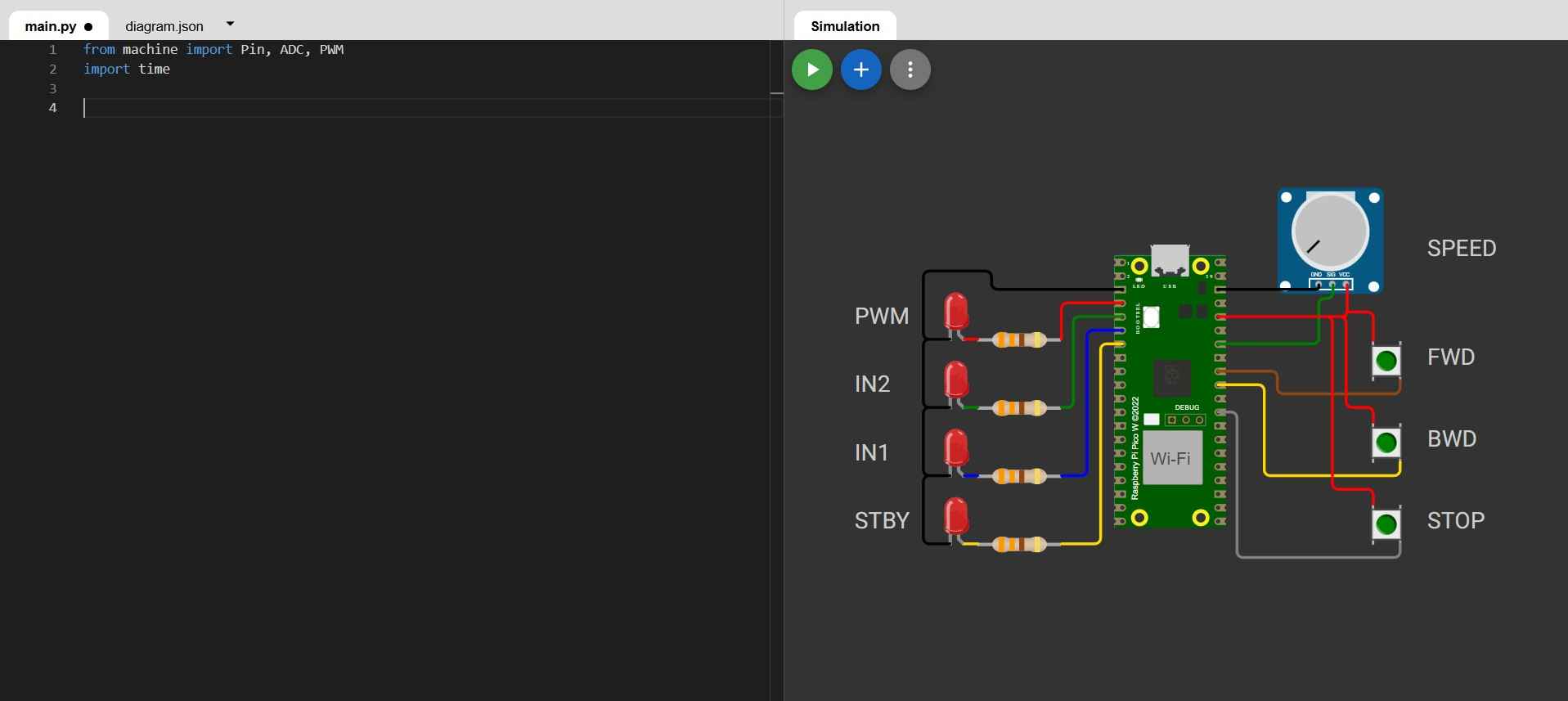
            from machine import Pin, ADC, PWM
            import time
The machine module is a built-in MicroPython component that provides access to hardware peripherals.Pin is needed to read digital inputs, like buttons, and drive digital outputs, like LEDs or direction pins.ADC is needed to read the potentiometer voltage. PWM is needed to generate the PWM output that represents motor speed. The time module is MicroPython's subset of utilities that allow print throttling and loop pacing.
6.2 Input and output pins
Next, the pins for the buttons, potentiometer, and LEDs are defined. The pin numbers correspond to the GPIO numbers on the Raspberry Pi Pico 2W development board.
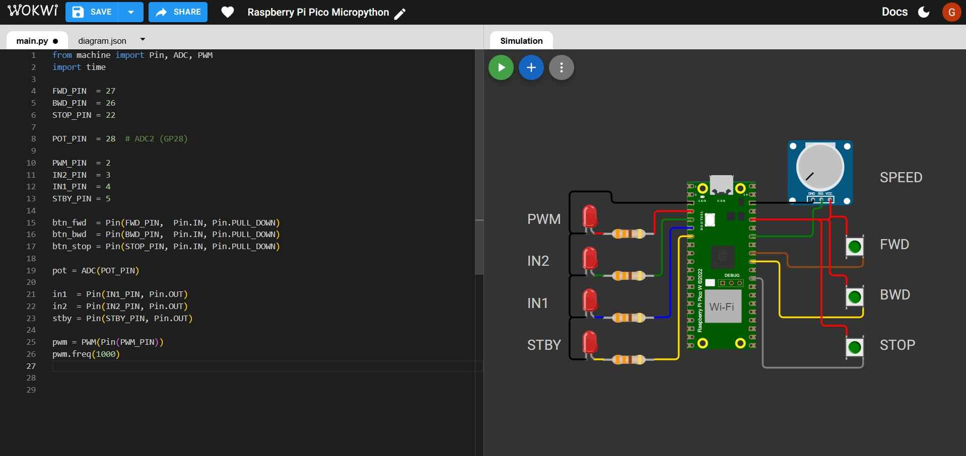
            FWD_PIN  = 27
            BWD_PIN  = 26
            STOP_PIN = 22
            POT_PIN  = 28  # ADC2 (GP28)
            PWM_PIN  = 2
            IN2_PIN  = 3
            IN1_PIN  = 4
            STBY_PIN = 5

            btn_fwd  = Pin(FWD_PIN,  Pin.IN, Pin.PULL_DOWN)
            btn_bwd  = Pin(BWD_PIN,  Pin.IN, Pin.PULL_DOWN)
            btn_stop = Pin(STOP_PIN, Pin.IN, Pin.PULL_DOWN)

            pot = ADC(POT_PIN)

            in1  = Pin(IN1_PIN, Pin.OUT)
            in2  = Pin(IN2_PIN, Pin.OUT)
            stby = Pin(STBY_PIN, Pin.OUT)

            pwm = PWM(Pin(PWM_PIN))
            pwm.freq(1000)
- btn_fwd = Pin(FWD_PIN, Pin.IN, Pin.PULL_DOWN), btn_bwd = Pin(BWD_PIN, Pin.IN, Pin.PULL_DOWN), and btn_stop = Pin(STOP_PIN, Pin.IN, Pin.PULL_DOWN) configure each button pin as an input in which an internal resistor pulls the pin to 0V when not pressed. Pin.IN= input mode, and Pin.PULL_DOWN activates the internal resistor. This prevents random 0/1 readings.
- An ADC object tied to GP28 is created by: pot = ADC(POT_PIN).
- FWD_PIN = 27, BWD_PIN = 26, and STOP_PIN = 22 are numeric GPIO identifiers for my button inputs. In case of rewiring, changing the number is all that is needed to reroute a signal.POT_PIN = 28 is used as an analog input (ADC2 channel on the Pico board).PWM_PIN = 2, IN2_PIN = 3, IN1_PIN = 4, and STBY_PIN = 5 are outputs that will light up LEDs as a stand-in for a motor driver.
- in1 = Pin(IN1_PIN, Pin.OUT), in2 = Pin(IN2_PIN, Pin.OUT) and stby = Pin(STBY_PIN, Pin.OUT) configure the specified pins as digital outputs that output HIGH/LOW signals.
- pwm = PWM(Pin(PWM_PIN)) creates a PWM controller attached to the PWM pin.
- pwm.freq(1000) sets PWM frequency to 1000Hz.
6.3 State variables and deadband

            state = 0

            last_fwd  = 0
            last_bwd  = 0
            last_stop = 0

            DEADBAND = 2000
- The variable state is set to 0 and determines the system's mode (0 = stopped, 1 = forward, 2 = backward). This helps enforce the rule against changing direction while the system is running.
- last_fwd, last_bwd, and last_stop are previous readings of the buttons; they allow edge detection in the event of the press of a button.
- Deadband is a threshold so tiny ADC readings are treated as zero.
6.4 Helper function
This function matches numeric states with readable strings; it is not required for control logic but for clean, understandable serial output.
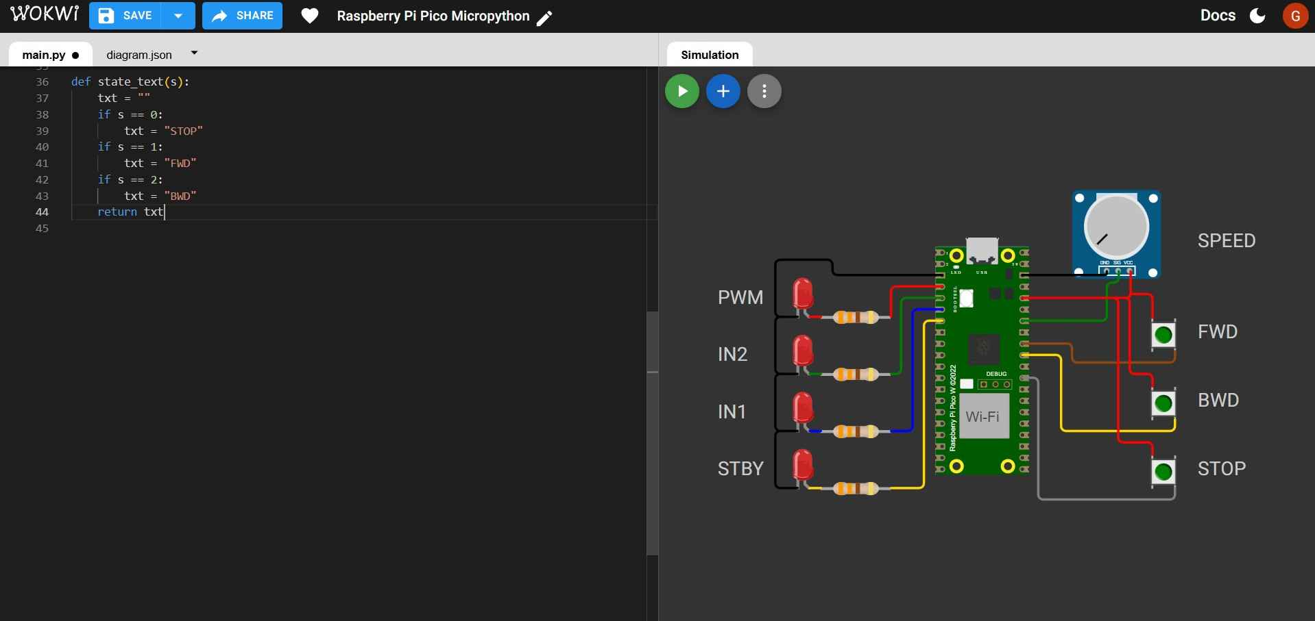
              def state_text(s):
                  txt = ""
                  if s == 0:
                      txt = "STOP"
                  if s == 1:
                      txt = "FWD"
                  if s == 2:
                      txt = "BWD"
              return txt
6.5 Print timing set up
- last_print_ms = time.ticks_ms() records the start time in milliseconds; this will be used to decide when it's time to print again without interrupting the rest of the code.
- PRINT_EVERY_MS = 200 is the time interval in milliseconds between prints. This allows for throttling print statements to avoid overwhelming the serial output and to maintain readability.

              last_print_ms = time.ticks_ms()
              PRINT_EVERY_MS = 200
6.6 Main loop, potentiometer and button values
The main loop of the program continuously checks the state of the buttons and the potentiometer, updating the system's state and outputs accordingly.

             while True:

                 raw = pot.read_u16()
                 volts = raw * 3.3 / 65535
                 duty = raw
                 if duty < DEADBAND:
                    duty = 0

                 f = btn_fwd.value()
                 b = btn_bwd.value()
                 s = btn_stop.value()
- raw = pot.read_u16() reads ADC as a 16-bit number (0-65535).
- volts = raw * 3.3 / 65535 converts the raw ADC reading to voltage (0-3.3V).
- duty = raw uses ADC reading directly for PWM duty.
- if duty < DEADBAND: duty = 0 eliminates small noise and ensures reliable auto-stop logic and a clean "zero speed."
- f = btn_fwd.value(), b = btn_bwd.value(), s = btn_stop.value() read the current state of each button (0 or 1).
6.7 Edge detection
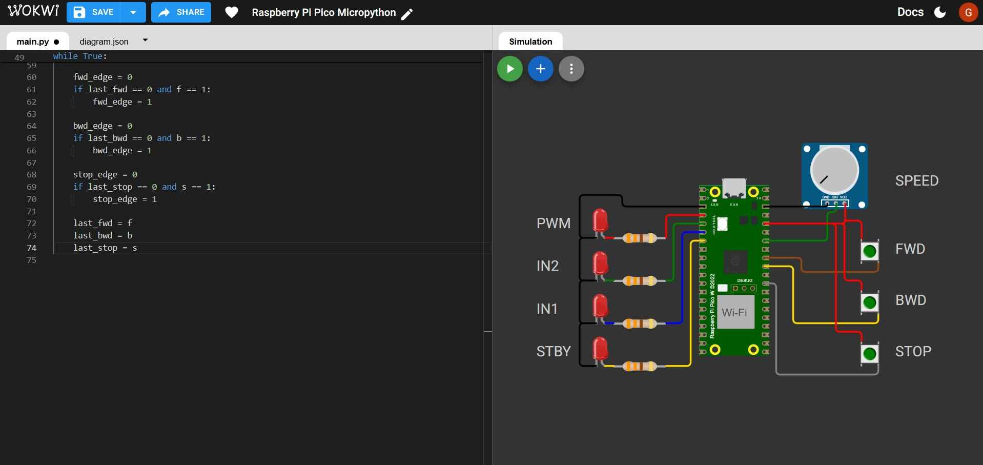
              fwd_edge = 0
              if last_fwd == 0 and f == 1:
                fwd_edge = 1

              bwd_edge = 0
              if last_bwd == 0 and b == 1:
                  bwd_edge = 1

              stop_edge = 0
              if last_stop == 0 and s == 1:
                  stop_edge = 1

              last_fwd = f
              last_bwd = b
              last_stop = s
- The line if last_fwd == 0 and f == 1: fwd_edge = 1 ensures that fwd_edge is set to 1 only when the button transitions from not pressed (0) to pressed (1). This prevents repeated triggering while holding the button down. The same logic applies for bwd_edge and stop_edge.
- The lines last_fwd = f, last_bwd = b and last_stop = s ensure that edge detection does not break.
6.8 Logic for state changes

            if state != 0 and duty == 0:
                state = 0

            if stop_edge == 1:
                state = 0

            if fwd_edge == 1:
                if duty > 0:
                    if state == 0:
                        state = 1

            if bwd_edge == 1:
                if duty > 0:
                    if state == 0:
                        state = 2
- The line if state != 0 and duty == 0: state = 0 forces STOP if the motor is running and speed becomes 0, this prevents a running state with no speed, matching a design requirement.
- The line if stop_edge == 1: state = 0 ensures that a STOP press overrides everything.
- The line if fwd_edge == 1: ensures that only one action occurs per press; if duty > 0, prevents the motor from starting with "zero" speed. The line if state == 0: enforces "no direction change while running" if state is already 1 or 2. The same logic applies to the condition involving bwd_edge.
6.9 Outputs
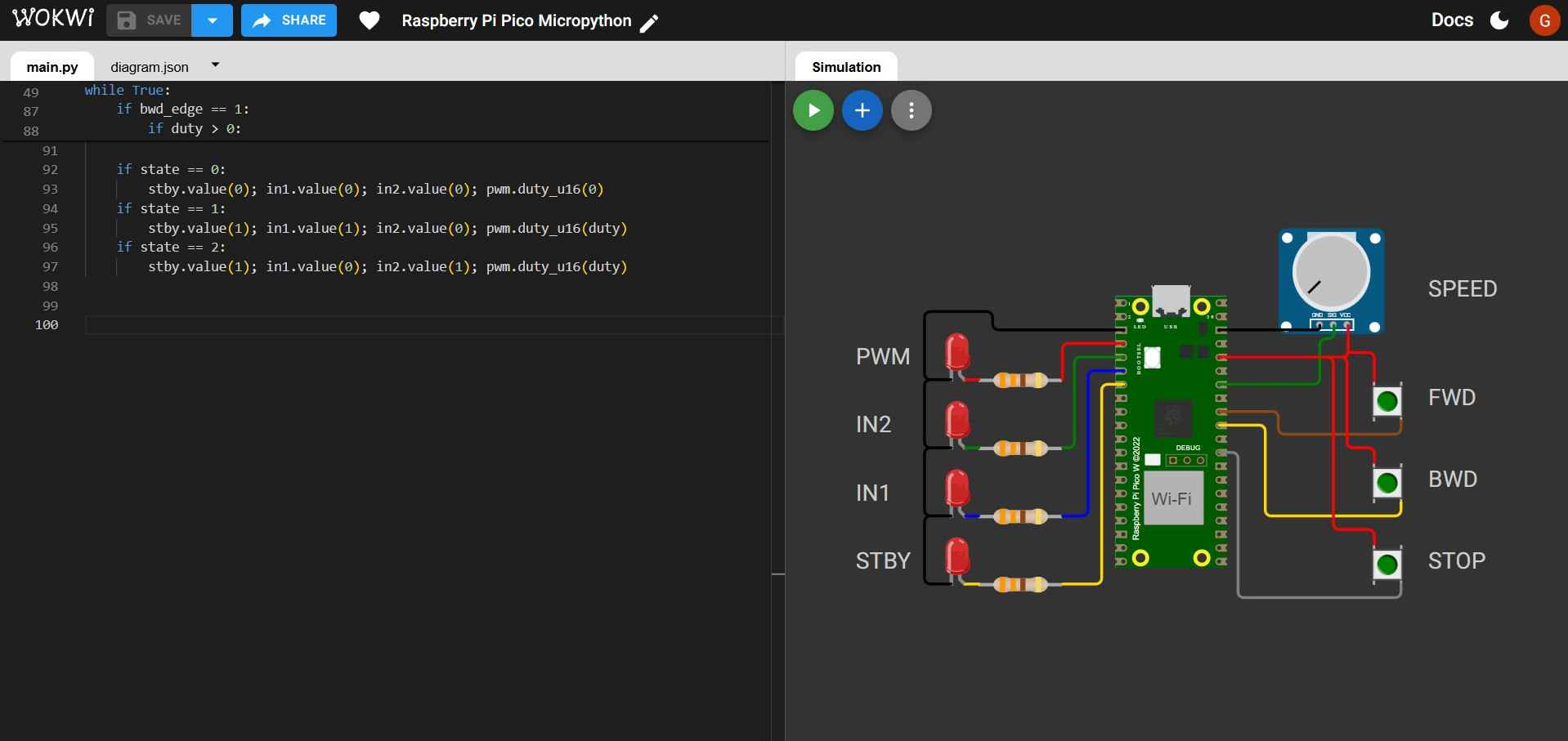
          if state == 0:
              stby.value(0); in1.value(0); in2.value(0); pwm.duty_u16(0)
          if state == 1:
              stby.value(1); in1.value(1); in2.value(0); pwm.duty_u16(duty)
          if state == 2:
              stby.value(1); in1.value(0); in2.value(1); pwm.duty_u16(duty)
- STOP state: if state == 0: stby.value(0); in1.value(0); in2.value(0); pwm.duty_u16(0) clears every digital output and sets PWM to 0 so the "motor" is off.
- FWD state: if state == 1: stby.value(1); in1.value(1); in2.value(0); pwm.duty_u16(duty) sets the motor to move forward at the specified duty cycle.
- BWD state: if state == 2: stby.value(1); in1.value(0); in2.value(1); pwm.duty_u16(duty) sets the motor to move backward at the specified duty cycle.
6.10 Serial print and timing
            now = time.ticks_ms()
            if time.ticks_diff(now, last_print_ms) >= PRINT_EVERY_MS:
                print("Estado:", state_text(state),
                      "| FWD:", f, "BWD:", b, "STOP:", s,
                      "| RAW:", raw, "| V:", "{:.2f}".format(volts),
                      "| DUTY:", duty)
                last_print_ms = now
            time.sleep_ms(10)
- The line now = time.ticks_ms() allows the code to keep looping normally; only when 200 ms have passed, state text, button values, raw ADC, voltage, and duty are printed. If any button is pressed before the next print time, the instruction still gets handled immediately.
- The line time.sleep_ms(10) prevents the loop from running thousands of times per second, wasting CPU; ticks and sleep work together, ticks makes periodic actions accurate, and sleep keeps the loop efficient and stable.
Here is a video showing the simulation running in Wokwi:
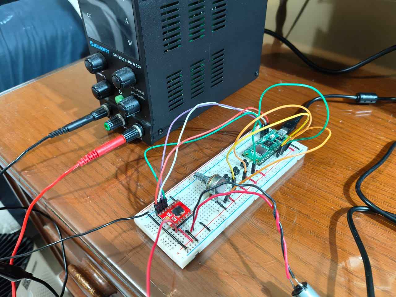
7. Testing the code on a physical board
After validating the code on the Wokwi simulator, I proceeded to test it on a physical circuit. The circuit was set up on a breadboard; instead of LEDs and resistors, I used a TB6612FNG driver and a 12-volt DC motor. The code was uploaded to the Pico using Thonny IDE, which provides a user-friendly interface for programming microcontrollers with MicroPython. During testing, I observed that the physical circuit did not behave as expected; after pressing a button, its variable values were not updating correctly in the serial monitor, and the motor did not respond accordingly. Nevertheless, the following pictures show how I flashed the firmware to the Pico.
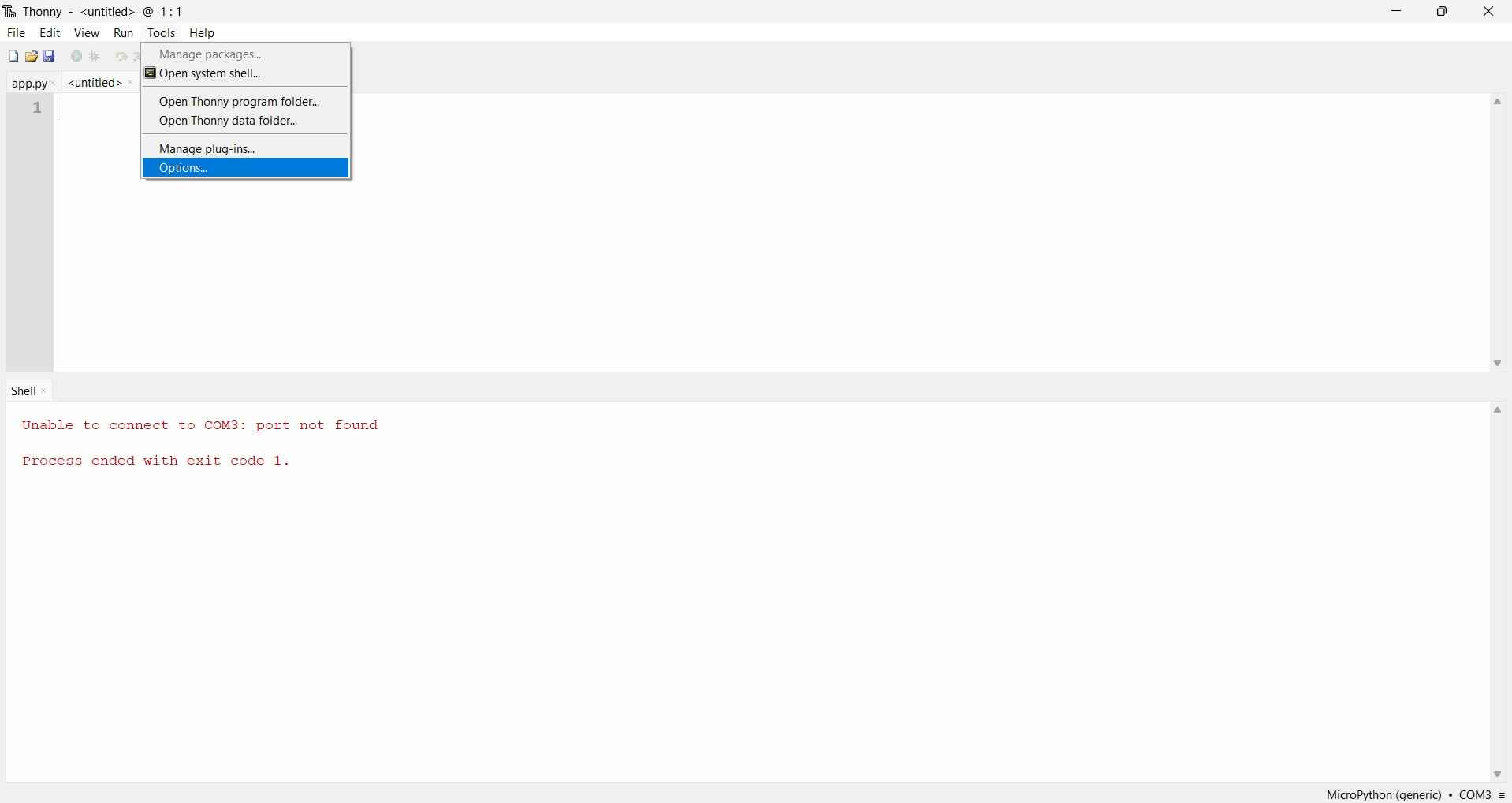
To flash firmware on a Raspberry Pi Pico 2W, the board must be connected to a computer while holding the BOOTSEL button at the same time so that it goes into bootloader mode. In the Thonny IDE, the first step for flashing a microcontroller is to select Options from the Tools menu.
The "Interpreter" tab in the Options menu lets users choose the microcontroller type and port. In this case, the Raspberry Pi Pico 2W was detected as "Raspberry Pi Pico (MicroPython)."
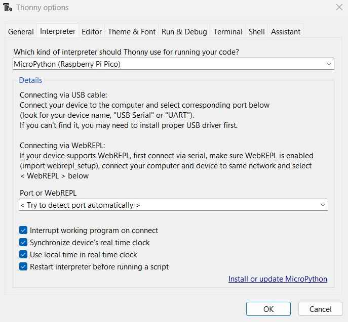
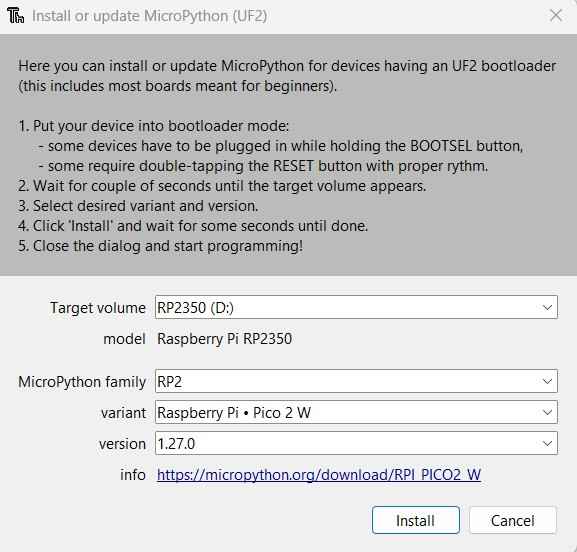
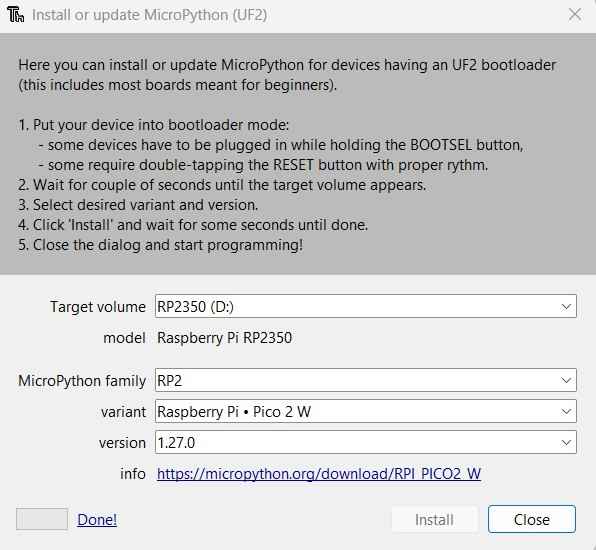
After clicking Install or Update MicroPython, the following window will open. I chose RP2350 (D:) as the target volume for my board, RP2 as the MicroPython family, and Raspberry Pi Pico 2 W as the variant.
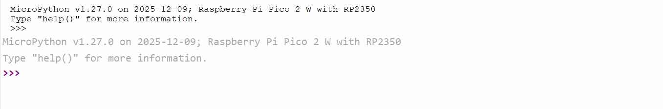
With the installation complete, a message on the Shell will show the interpreter used and the microcontroller plugged into the computer.
After flashing the firmware, I copied my Wokwi code to the Pico and executed it by pressing the "Run current script" button. However, the code did not execute properly; after pressing one button, its variables remained in a high logic state. This issue prevented the corresponding state from being activated for each button. After some debugging, I resolved the problem by changing my inputs from Pin.PULL_DOWN to Pin.PULLUP. This change required a simple change in the circuit, a terminal from each push button will now be connected to a common GND terminal instead to VCC.
              btn_fwd  = Pin(FWD_PIN,  Pin.IN, Pin.PULL_UP)
              btn_bwd  = Pin(BWD_PIN,  Pin.IN, Pin.PULL_UP)
              btn_stop = Pin(STOP_PIN, Pin.IN, Pin.PULL_UP)
With the pull-up configuration, the buttons read a high logic state when not pressed and a low logic state when pressed. This change required inverting the logic for edge detection and state changes. Additionally, I implemented a debounce function to ensure that only one action is triggered per button press, even if the button is pressed multiple times in quick succession.
            def pressed_edge(read_now, last_read, last_change_ms):
                edge = 0
                now_ms = time.ticks_ms()

                if read_now != last_read:
                    if time.ticks_diff(now_ms, last_change_ms) >= DEBOUNCE_MS:
                        last_change_ms = now_ms

                        if last_read == 1 and read_now == 0:
                            edge = 1

                        last_read = read_now

                return edge, last_read, last_change_ms
After implementing these changes, the code ran as expected on the physical circuit. The following video shows the final result.
8. Files
Here are the downloadable files for this week:
Code for the Wokwi simulation (MicroPython) Code for the physical circuit (MicroPython)Reflection
This week I learned more about a specific microcontroller I am considering as a component on my final project. Though I have used simulators like Proteus before, I found Wokwi to be a competent one. This assignment reinforced my belief that every simulator has limitations and that physical testing is essential for reliable results.