Week 02: Computer-Aided Design
This week, we were introduced to computer-aided design (CAD). The Fab Academy program focuses on teaching digital fabrication techniques, and CAD is the initial step in transforming an idea into digital data that can be realized using fabrication equipment. For this week's assignment, we evaluated various 2D and 3D software programs to select the ones we will use throughout the Fab Academy assignments and our final project. We also reviewed tools for image and video compression.
Work log
Completed tasks
- Selected and evaluated 2D and 3D CAD software (pending).
- Demonstrated and described processes used in modelling with 2D and 3D softwares (pending).
- Demonstrated image and video compression.
Evidence
1. What is CAD?
CAD stands for Computer-Aided Design, referring to the use of specialized software to create detailed technical drawings and models used in engineering, architecture, manufacturing, and other fields. CAD is not limited to 3D representations; it encompasses both 2D and 3D work, each suited to different applications and industry needs.
2D CADTwo-dimensional (2D) CAD is often used to create flat technical drawings, blueprints, and schematics. It is widely used for:
- Architectural floor plans.
- Electrical/electronic schematics.
- Mechanical detail drawings (with orthographic views).
- PCB layouts.
Three-dimensional (3D) CAD is suited for creating volumetric models that can be rotated, simulated, rendered, and exported for manufacturing by CNC, 3D printing or injection molding.
- Solid modeling: Defines fully enclosed volumes.
- Surface modeling: Defines complex curved shells, common in automotive/industrial design.
- Parametric modeling: Geometry driven by editable parameters/constraints, very powerful for iterative design.
2. Evaluating 3D CAD software
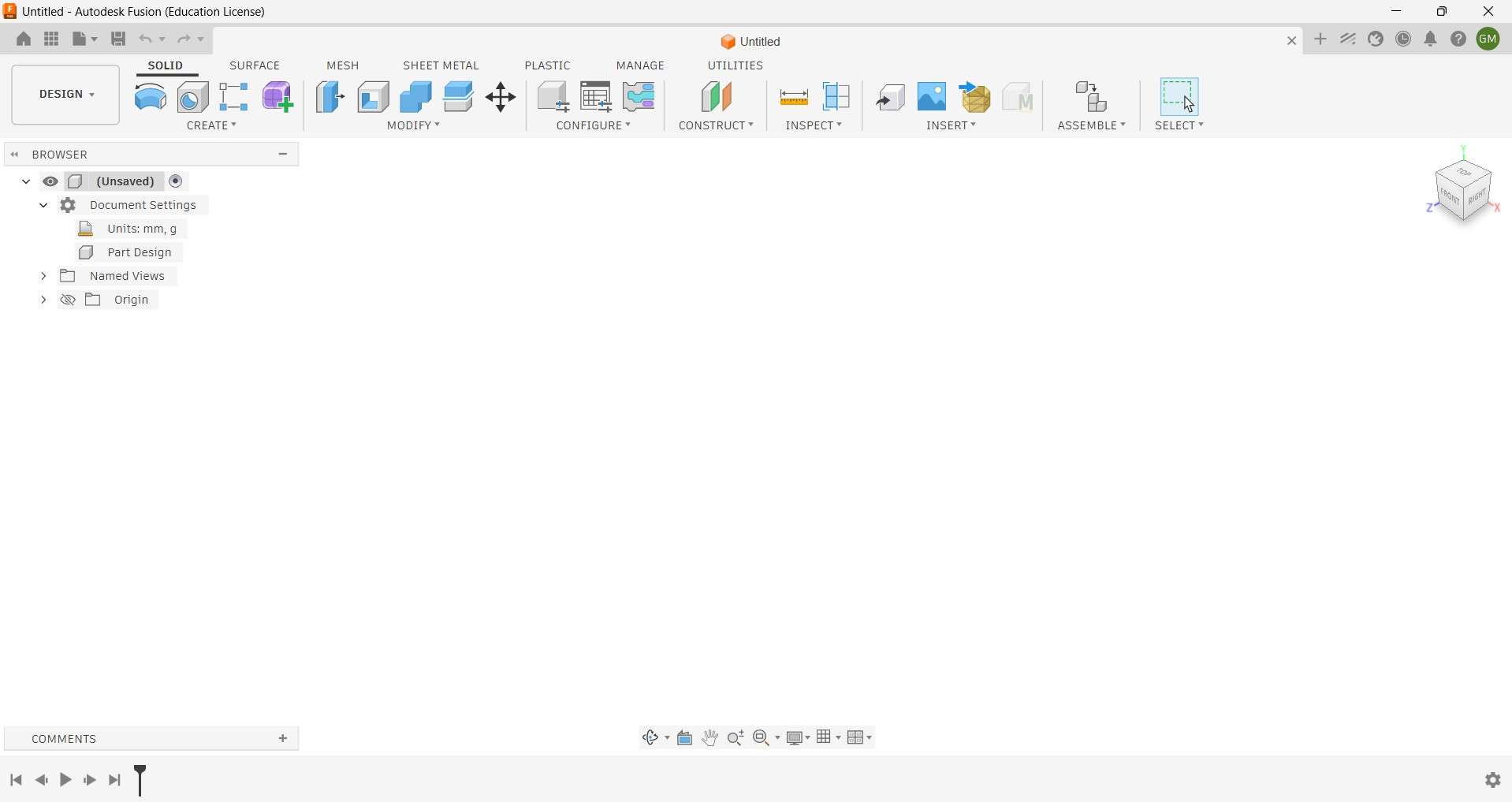
Fusion 360
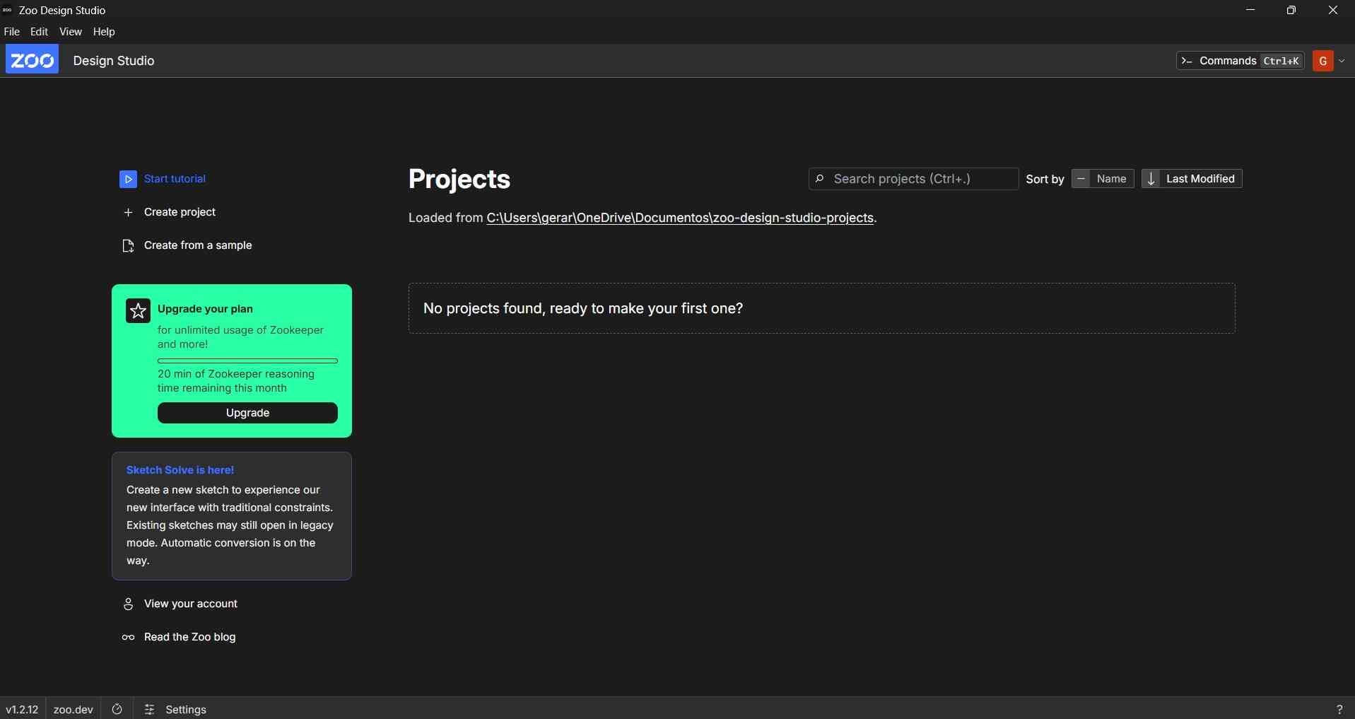
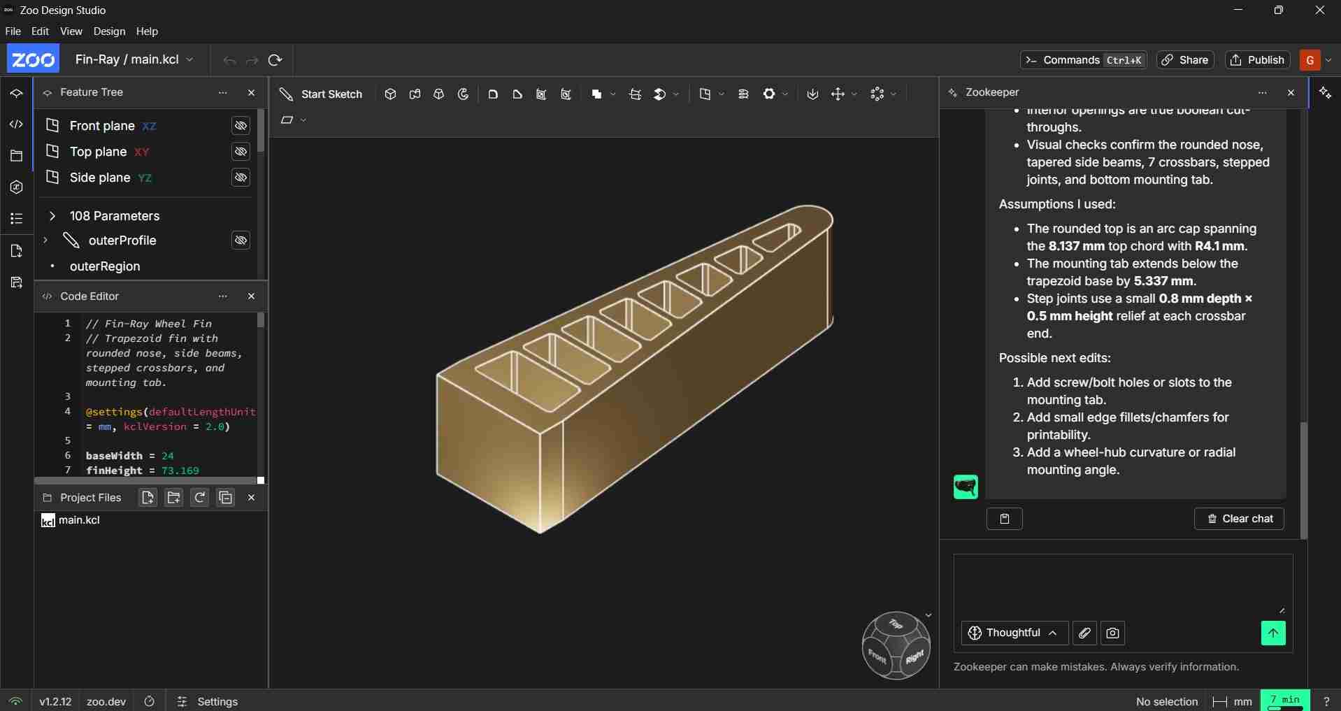
Zoo Design Studio
Accelerated by 100
3. Evaluating 2D CAD software
For the 2D section of this assignment, I initially considered several options: an isometric drawing of my robot, a top-down map marker, or a logo. Ultimately, I chose to design a logo that reflects both the bio-inspired aspects of my robot and its connection to satellites for world exploration, as described in my final project proposal.To represent this concept, I created a logo featuring an ant with satellites in place of its antennae. In nature, ants use their antennae to sense their environment—similarly, in my project, the satellites (through RTK technology) will help the robot navigate and monitor its surroundings. Additionally, I wanted the logo to include text that reflects the robot’s characteristics. I chose the name ANTSAR—short for ANT Search and Rescue—since my original goal was to develop the robot as a search and rescue platform. After deciding on the logo concept, I selected two different 2D design tools to compare their effectiveness by recreating the same logo in each. To begin, I sourced elements from Vecteezy, specifically an ant silhouette and a satellite graphic. Since I have a Pro Plan subscription with Vecteezy, I am not required to provide attribution for these downloaded elements.
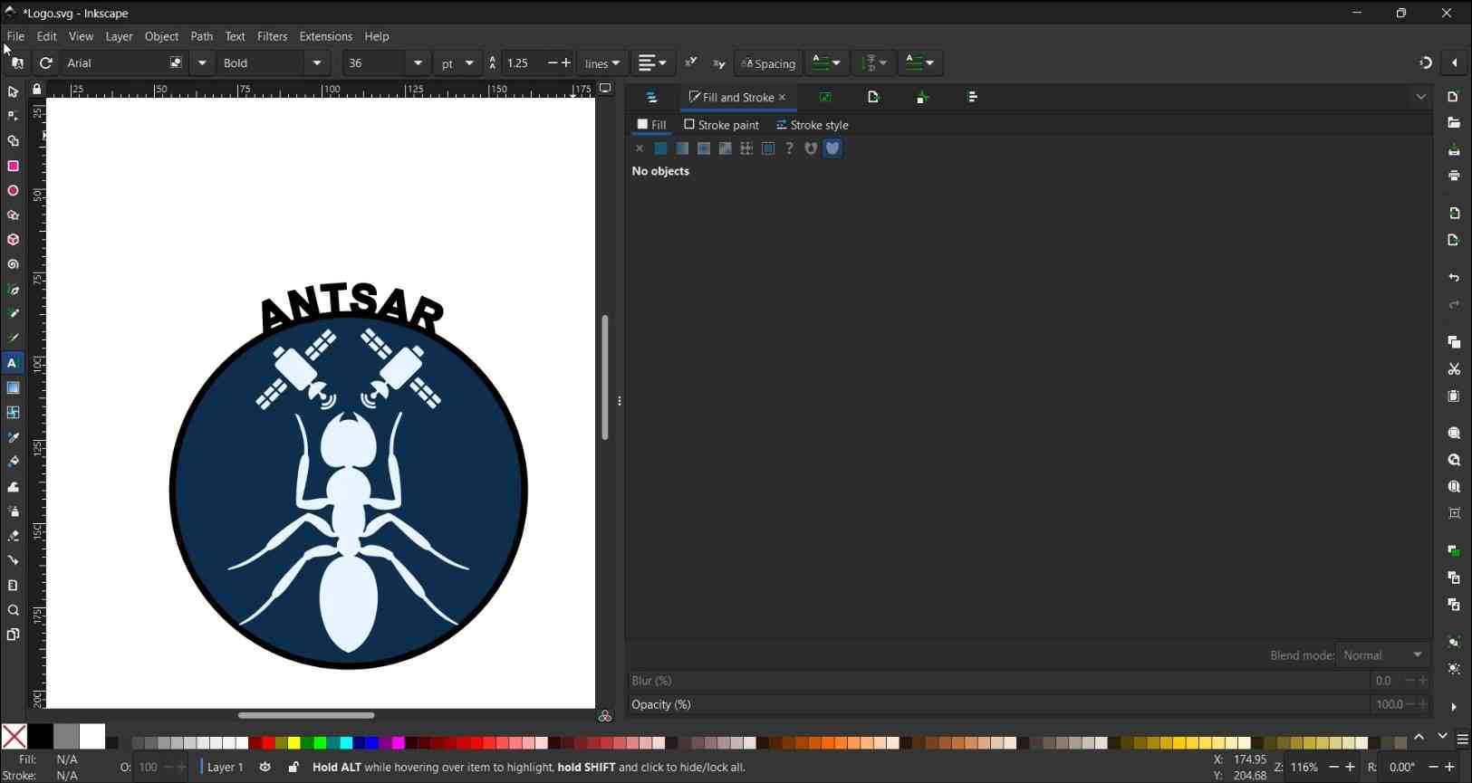
Inkscape
Inkscape is an open-source vector graphics editor that offers capabilities similar to those of Adobe Illustrator, CorelDraw, and Xara X. Unlike these alternatives, Inkscape is free to use and can be modified under the GNU General Public License. It utilizes the Scalable Vector Graphics (SVG) format, which is advantageous for web and laser-cut applications. Inkscape is widely used for creating and editing vector graphics, images defined by mathematical paths instead of pixels, allowing them to scale to any size without losing quality. You can download Inkscape for free by visiting the official website here.
After downloading and installing Inkscape, you can begin creating 2D designs by using the various elements and tools available within the interface.
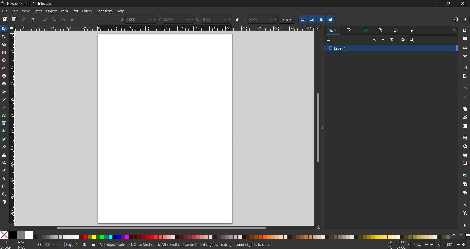
- Menu bar (top): Standard menus such as File, Edit, View, Object, Path, Text, Filters, Extensions, and Help.
- Commands bar: Quick-access icons for common actions like new, open, save, zoom, and snap controls.
- Tool controls bar: Context-sensitive options, such as X/Y coordinates, width/height dimensions, and units, that change depending on the active tool.
- Toolbox (left vertical bar): All drawing and editing tools, including selector, node editor, shapes, pen, text, and zoom.
- Rulers (top and left edges): Horizontal and vertical rulers for precise positioning and alignment.
- Canvas/Drawing Area (center): The main workspace; the white rectangle represents the document page where artwork is created.
- Layers Panel (right): Displays the layer stack for organizing objects.
- Color Palette (bottom strip): A row of color swatches for quickly applying fill or stroke colors.
- Status Bar (very bottom): Shows information about the curent fill/stroke, opacity, active layer, cursor coordinates, zoom level, and context-sensitive hints.
- Scroll Bars: Located along the bottom and right edges for navigating the canvas.
The creation process for this logo encompass the following steps:
1. Document Setup.
Opened Inkscape and created a new document (File > New).
2. Importing the ant image.
Imported the ant JPG (File > Import > Embed > Ok).
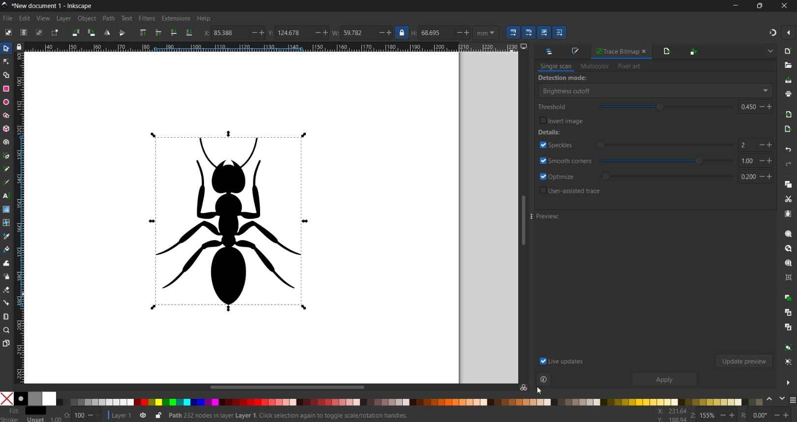
3. Vectorizing the ant.
- Selected the image and opened the trace tool (Path > Trace Bitmap).
- Settings: Mode: Single scan, Detection: Brightness cutoff, Threshold: 0.500
- Enabled "Smooth" and "Remove background".
- Clicked "Apply" and closed the panel.
- Deleted the original JPG, keeping only vector path.
4. Importing and vectorizing the satellite.
I repeated the same trace process as with the ant image, using identical settings.
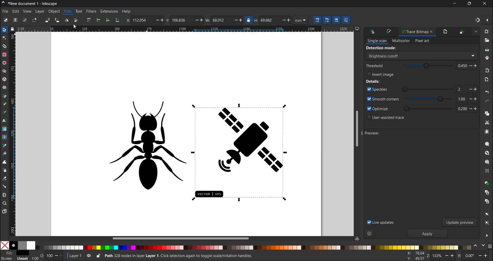
5. Cleaning the satellite
Removed unwanted elements (VECTOR | EPS text) using Path > Break Apart to separate paths, deleted the text shape, then rejoined with Path > Combine.
6. Scaling the elements
- Scaled the ant to approximately 300-400 px tall using the selection tool, holding Ctrl to scale proportionally.
- Scaled the satellite to approximately 1/4 size of the ant.
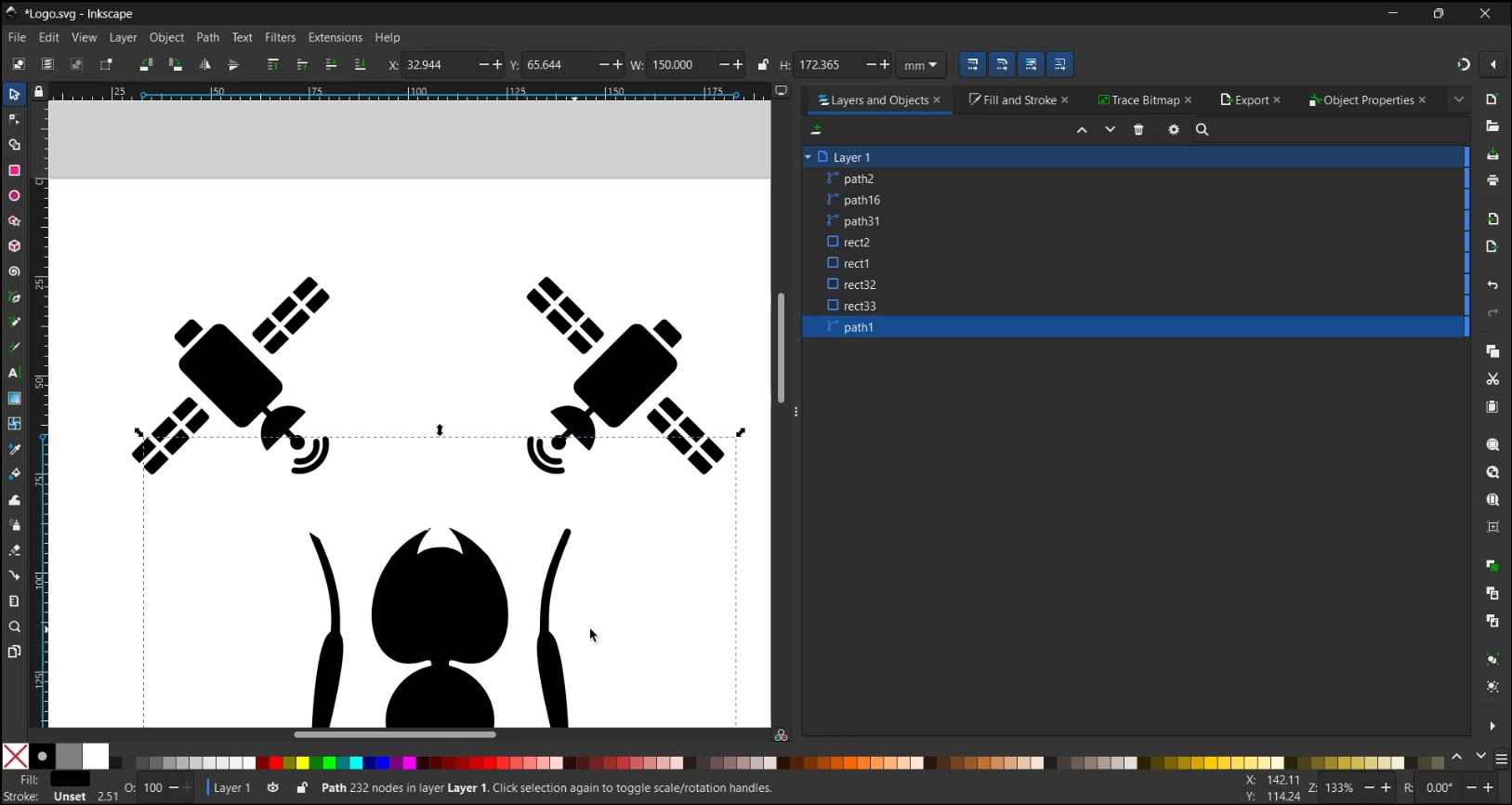
7. Duplicating and rotating the satellites.
- Duplicated the satellite (Edit > Duplicate/ Ctrl+D).
- Rotated each satellite using Object > Transform > Rotate tab, approximately ±45°.
- Positioned one satellite above each ant antenna.
- Applied an Object Flip Horizontal operation on the duplicated satellite.
8. Hiding the original ant antennae.
- Drew white rectangles over the original antennae using the Rectangle tool (R).
- Set Fill to white (FFFFFFFF) via Object > Fill and Stroke (Shift + Ctrl + F).
- Set stroke to none.
- Raised rectangles to top using Object > Raise to Top (Home Key)
9. Grouping the elements.
- Selected the ant and satellites together.
- Grouped them using Object > Group (Ctrl + G).
10. Drawing the circular badge.
- Used the Ellipse tool (E), held Ctrl to draw a perfect circle.
- Set Fill to none (X) and Stroke to black, width 2mm via Object > Fill and Stroke (Shift + Ctrl + F).
11. Centering elements.
- Opened Align and Distribute (Object > Align and Distribute / Shift + Ctrl + A).
- Set "Relative to" to "Biggest object".
- Applied "Center on vertical axis" and "Center on horizontal axis".
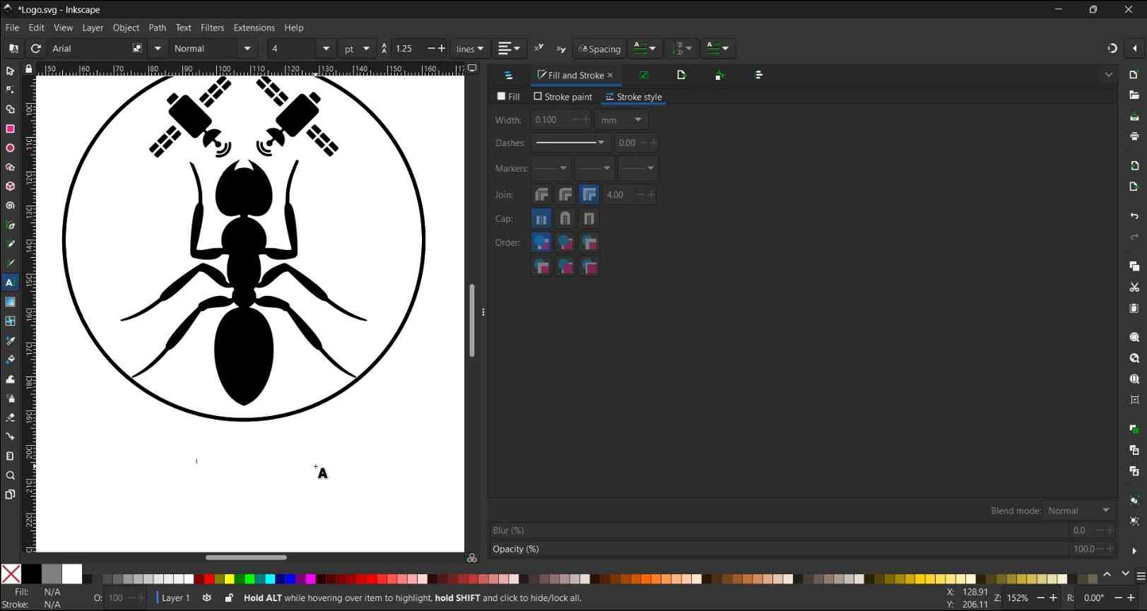
12. Adding text on path.
- Duplicated the circle (Edit > Duplicate / Ctrl + D).
- Used the Text tool (T) to write "ANTSAR", font Arial Bold, size 16 pt.
- Selected the text first, then shift+clicked the duplicate circle.
- Applied Text > Put on Path.
- Opened XML Editor (Edit > XML Editor / shift + Ctrl + X).
- Navigated to text > textpath and added attribute startoffset with value 67.1% to center the text at the top arc.
13. Applying colors.
- Selected the circle and set Fill to dark navy blue (0D2F4FFF) via Object > Fill and Stroke.
- Changed white rectangle fills to match the circle color (0D2F4FFF) and removed their strokes.
- Selected the ant and set Fill to light blue (E8F4FFFF).
- Selected both satellites and set Fill to the same light blue (E8F4FFFF).
14. Adjusting the document size.
- Opened Document Properties (File > Document Properties / Shift+Ctrl+D).
- Clicked "Resize page to drawing or selection" to fit the page to the logo.
15. Adding a white background.
- Drew a rectangle covering the full page with the Rectangle tool (R).
- Set Fill to white (FFFFFFFF) and Stroke to none.
- Moved it to the bottom of the layer stack (Object > Lower to Bottom / End key).
16. Exporting the final PNG.
- Opened Export panel (File > Export / Ctrl+Shift+E).
- Set Export area to "Page", DPI to 96.
- Clicked "Export As", named the file, and clicked "Export"
Affinity

The creation process for this logo encompass the following steps:
1. Document Setup.
Opened Inkscape and created a new document (File > New).
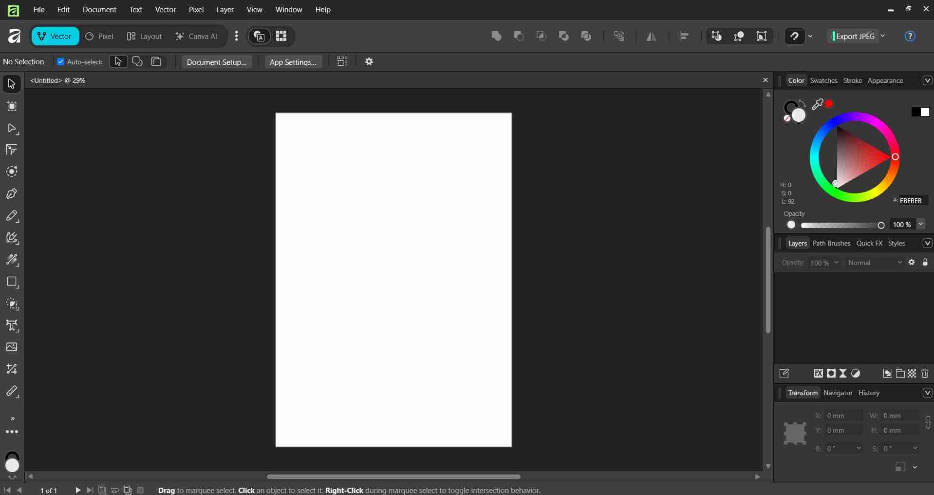
- Opened Affinity Designer and clicked the green + button.
- Selected document size 150x150mm, 300 DPI, RGB color format.
- Clicked "Create Document".
2. Importing the ant image.
- Imported the ant JPG (File > Place).
- Clicked on the canvas to place the image.
3. Vectorizing the ant.
- Selected the image and opened the trace tool (Vector > Image Trace).
- Settings: Edge Threshold: 50%, Curve Fitting Tolerance: 40%.
- Clicked "Apply".
4. Importing and vectorizing the satellite.
- Repeated the same import and trace process with the satellite JPG (File > Place, then Vector > Image Trace with identical settings).
- Clicked "Apply".
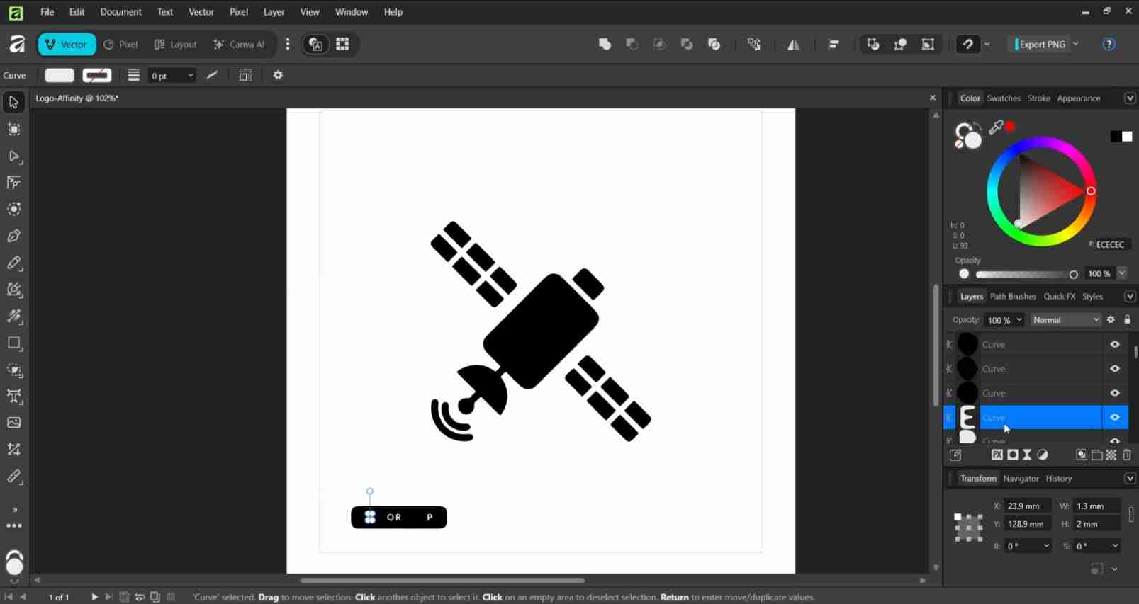
5. Cleaning the satellite.
- Separated the satellite paths by right-clicking and selecting "Ungroup".
- Deleted unwanted elements (VECTOR | EPS text and white backgrounds) by clicking each one and pressing Delete.
6. Scaling the elements.
- Scaled the ant to fill most of the canvas by dragging corner handles while holding Ctrl to scale proportionally.
- Scaled the satellite to approximately 1/4 the size of the ant using the Transform panel (W: 36.9mm, H: 36.9mm).
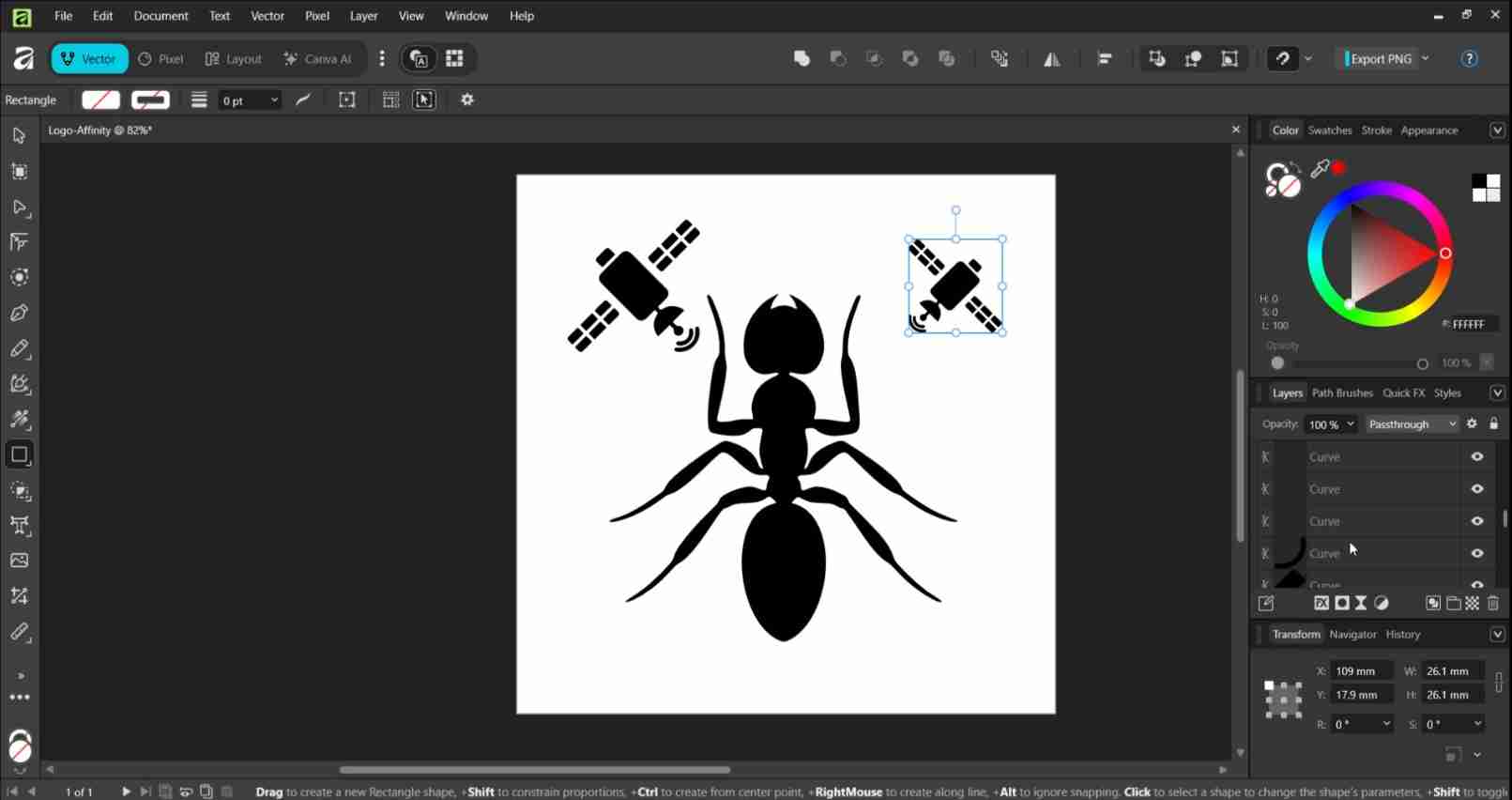
7. Duplicating and rotating the satellites.
- Duplicated the satellite (Edit > Duplicate / Ctrl+J).
- Rotated each satellite by clicking twice to get rotation handles and dragging.
- Positioned one satellite above each ant antenna.
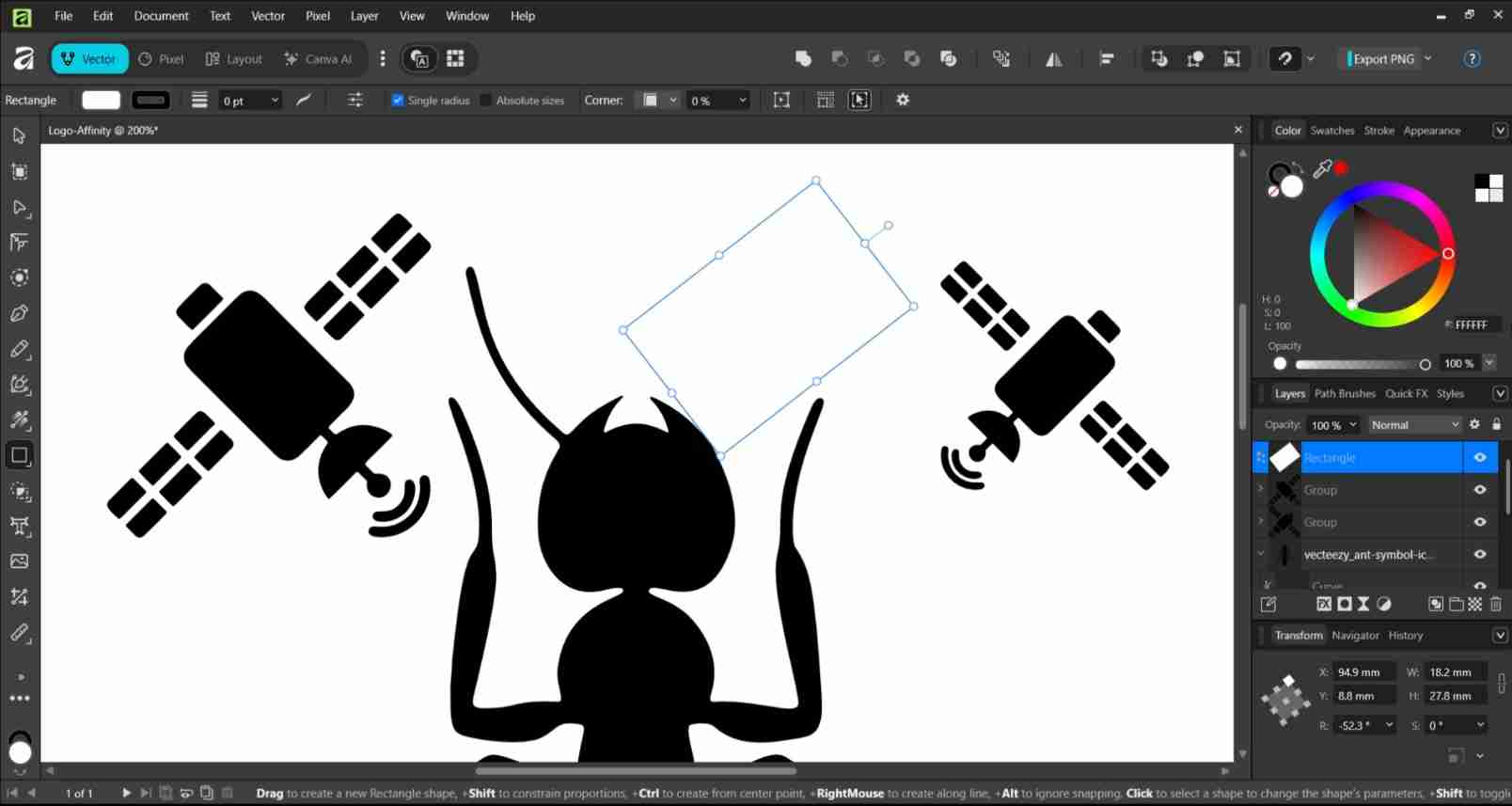
8. Hiding the original ant antennae.
- Drew white rectangles over the original antennae using the Rectangle tool (M).
- Set Fill to white (FFFFFF) via the Color panel (right side).
- Set Stroke to 0pt in the top toolbar.
- Raised rectangles above the ant in the Layers panel by dragging them up.
9. Equalizing satellite sizes.
Selected each satellite and matched their dimensions in the Transform panel (bottom right), setting both to W: 36.9mm, H: 36.9mm.
10. Grouping and aligning the satellites.
- Selected both satellites with Shift+click
- Grouped them (Layer > Group / Ctrl+G)
- Aligned satellites to the same Y position using Arrange > Align.
- Manually centered the satellite group relative to the ant using the Transform panel coordinates:
- Ant center: X 72.9mm (X: 27.9mm + W: 90mm / 2)
- Satellite left X set to: 41.45mm
- Satellite right X set to: 80.1mm
11. Drawing the circular badge.
- Used the Ellipse tool (E), held Ctrl to draw a perfect circle large enough to contain all elements.
- Set Fill to none using the Color panel.
- Set Stroke to black, width 2-3pt via the Stroke panel.
- Moved the circle to the bottom of the layer stack in the Layers panel.
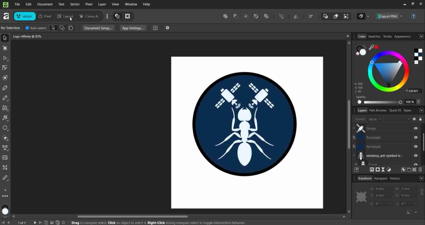
12. Applying colors.
- Selected the circle and set Fill to dark navy blue (0D2F4F) via the Color panel.
- Changed white rectangle fills to match the circle color (0D2F4F) and removed their strokes.
- Selected the ant and set Fill to light blue (E8F4FF).
- Selected the satellite group and set Fill to the same light blue (E8F4FF).
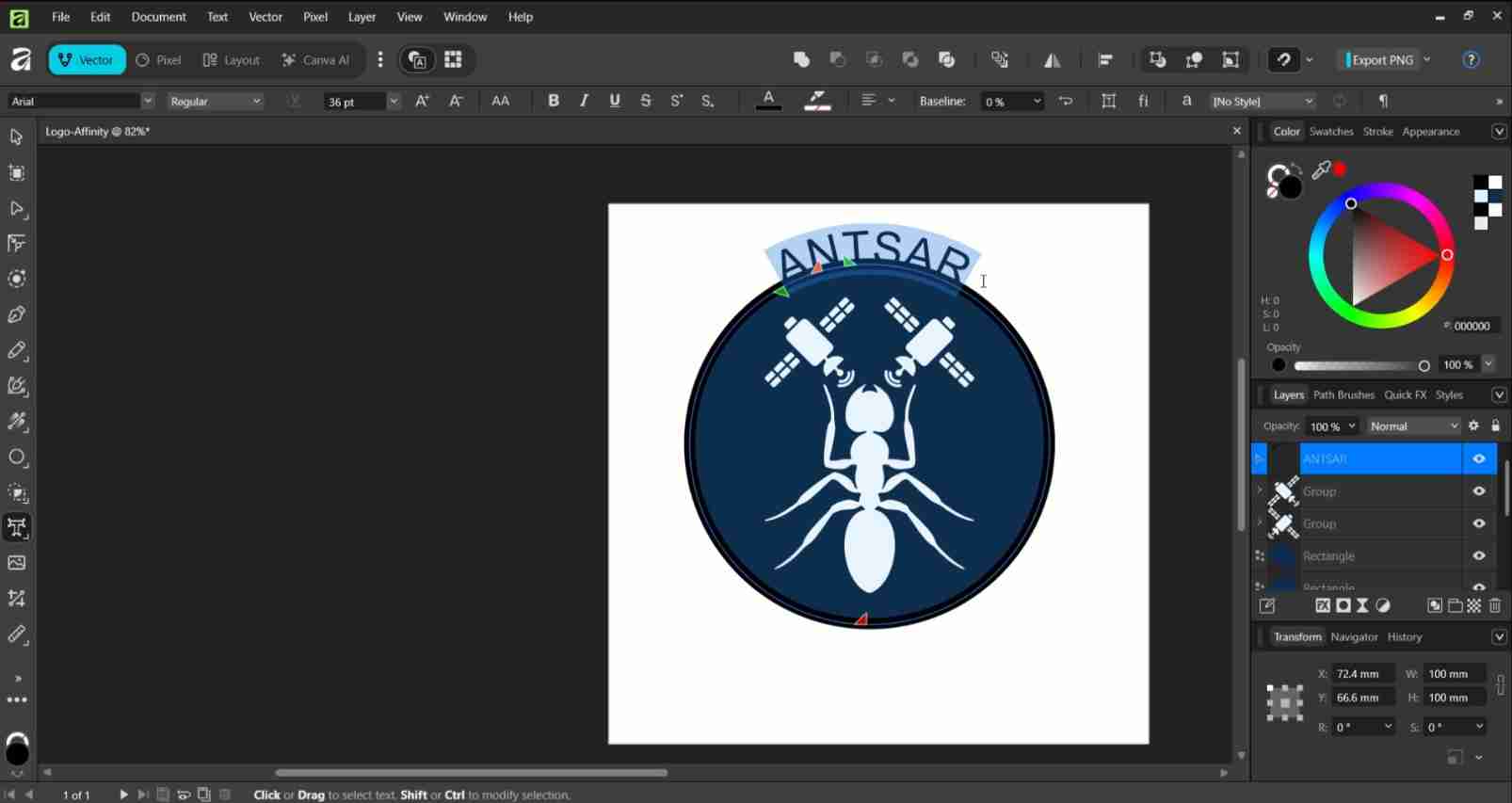
13. Adding text on a path.
- Duplicated the circle (Ctrl+J).
- Selected the Text tool (T) and hovered over the edge of the duplicate circle until the cursor changed to a text-on-path icon.
- Clicked on the circle edge and typed "ANTSAR".
- Changed font to Arial Bold, size 16-18pt in the top toolbar.
- Dragged the orange anchor point to position the text at the top arc.
14. Adjusting the document size.
- Opened Document Setup (Document > Document Setup).
- Adjusted Page width and Page height to fit the logo (120x120mm).
- Clicked "OK".
15. Exporting the final PNG.
- Clicked the Export PNG button in the top right corner.
- Set DPI to 96.
- Named the file ANTSAR_logo_Affinity and clicked "Export".
4. Image and video compression
Documentation often lacks completeness without images and videos to support written content. However, image and video files tend to be large, which can result in slower loading times on websites. Additionally, our Fab Academy repositories must not exceed 100 MB in size by the end of the program. Therefore, using image and video compression tools is essential to meet the size requirements for repositories and to enhance the accessibility of our repository websites, especially for users with slow internet connections.
Image and video compression reduce the amount of data needed to store or transmit visual content. There are two main types of compression. The first type is lossless compression, where no information is permanently discarded, allowing the original file to be perfectly reconstructed. The second type is lossy compression, which discards some information to create much smaller files, typically resulting in a minor loss of visible quality.
4.1. Image compression
Image compression reduces the file size of individual images while aiming to maintain acceptable quality for accurately depicting content. This process eliminates redundancy and less noticeable visual details. Our instructors recommended consistently uploading images to our repositories in JPEG format. JPEG, which stands for Joint Photographic Experts Group, is an international organization that standardized this format during the late 1980s and early 1990s. A JPEG file supports up to 24-bit color and utilizes lossy compression to decrease image file size, making storage and transmission more convenient.
The following are the filename extensions for JPEG images:
- .jpg
- .jpeg
- .jpe
- .jif
- .jfif
- .jfi
JPEG files were designed to deliver photorealistic images to small screens worldwide. However, their compression technique discards colors that the human eye cannot distinguish and averages out color variations. This file format supports up to 16.8 million colors while maintaining a relatively small size, ensuring compatibility with most browsers, software, and applications.
The process I chose for image compression involves using the Windows Snipping Tool app, WhatsApp messages, and the online image compression tool FabCompress, which was developed by Rafael Perez Aguirre.
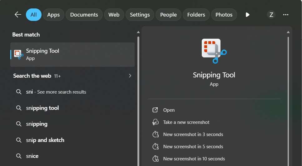
Given that the core of Fab Academy is teaching digital fabrication techniques, it is essential for us to inform our peers and instructors about the processes we utilized to complete our assignment tasks. These processes often involve preparing manufacturing files on a computer, making a tool for capturing screen frames necessary. For this purpose, I have chosen to use the Snipping Tool, which is preinstalled on most Windows distributions. The Snipping Tool can be accessed by pressing the Windows key + Shift + S or by typing "Snipping Tool" directly into the Windows search bar.
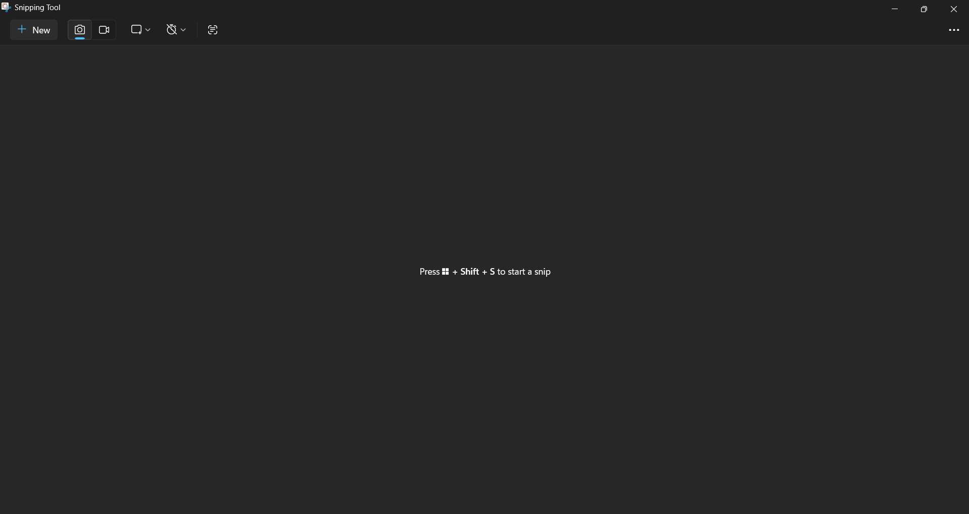
Once we can visualize Snipping Tool's main window, we can click on the + symbol in the top left corner to capture a frame from our computer screen. Starting the process will change our cursor from an arrow to a cross. With our cursor in this state, we can click on a specific region of our screen and start dragging it to draw a rectangle that captures the desired area. After capturing the frame, we can edit our image by adding figures or drawings to highlight certain elements. After editing our image, we can save it in a desired folder.
The following video shows the process of capturing a frame using the Snipping Tool:
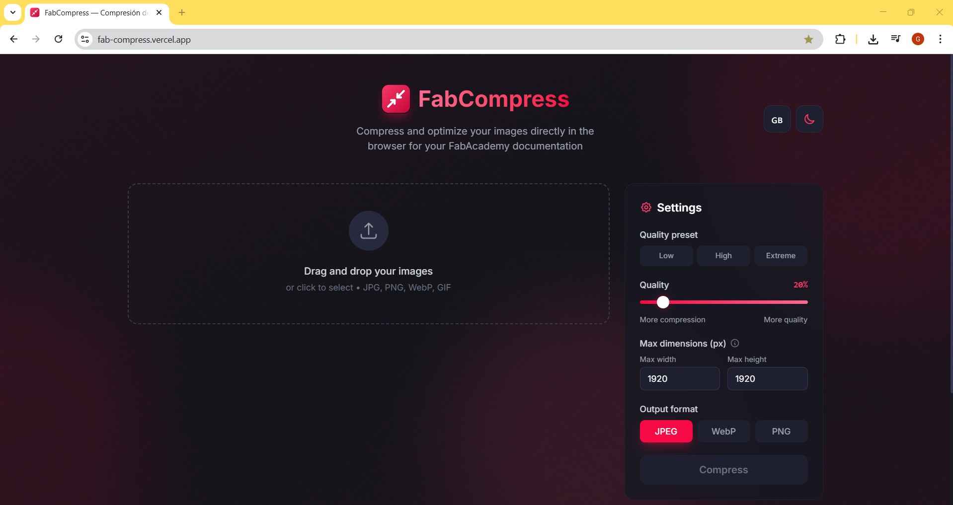
As mentioned earlier, I will use FabCompress to compress the images in my repositories. In fact, FabCompress has successfully compressed every image displayed on this page. FabCompress is an online tool, which means it is not necessary to install it on a personal computer. The main window of FabCompress provides options for setting the output format of our image files, maximum width and height, and quality. Additionally, this tool supports batch compression, allowing multiple images to be compressed simultaneously.
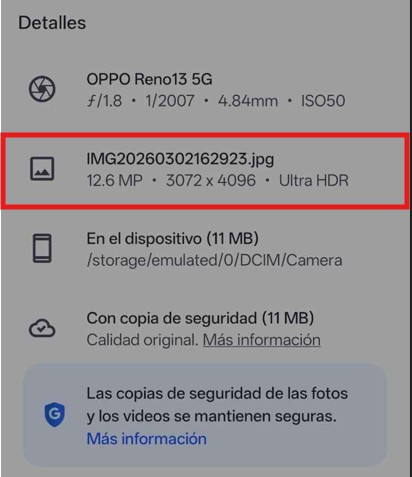
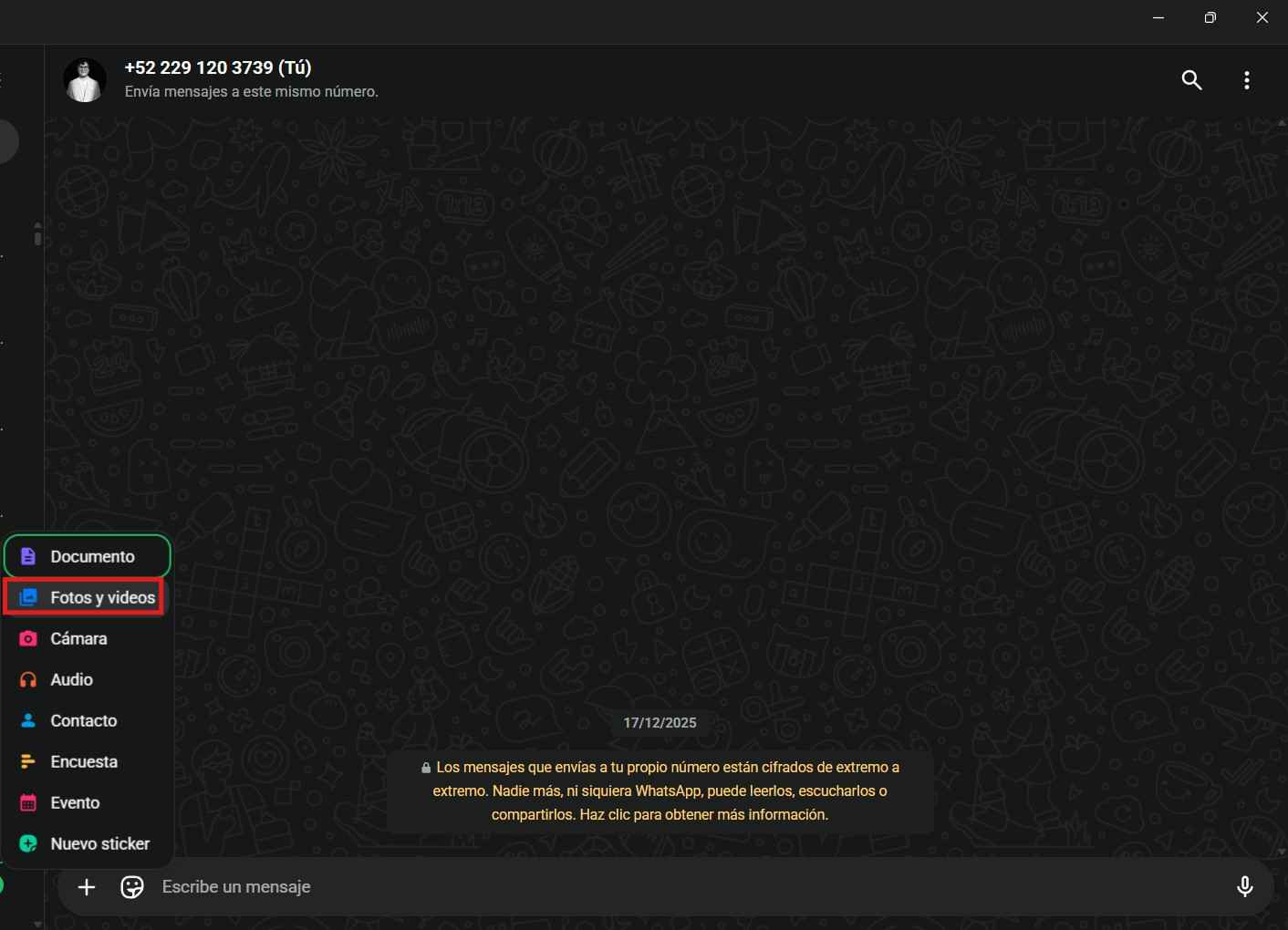
Aside from computer screenshots, documentation often requires photos taken with a camera, usually a smartphone. In this case, I opted to transfer images from my phone to my computer using the WhatsApp messaging app. The key to effective image compression through WhatsApp is to send the pictures as chat images instead of files. This method compresses the images while still preserving impressive quality. To demonstrate the results of WhatsApp image compression, I have chosen this image that I captured with my smartphone.
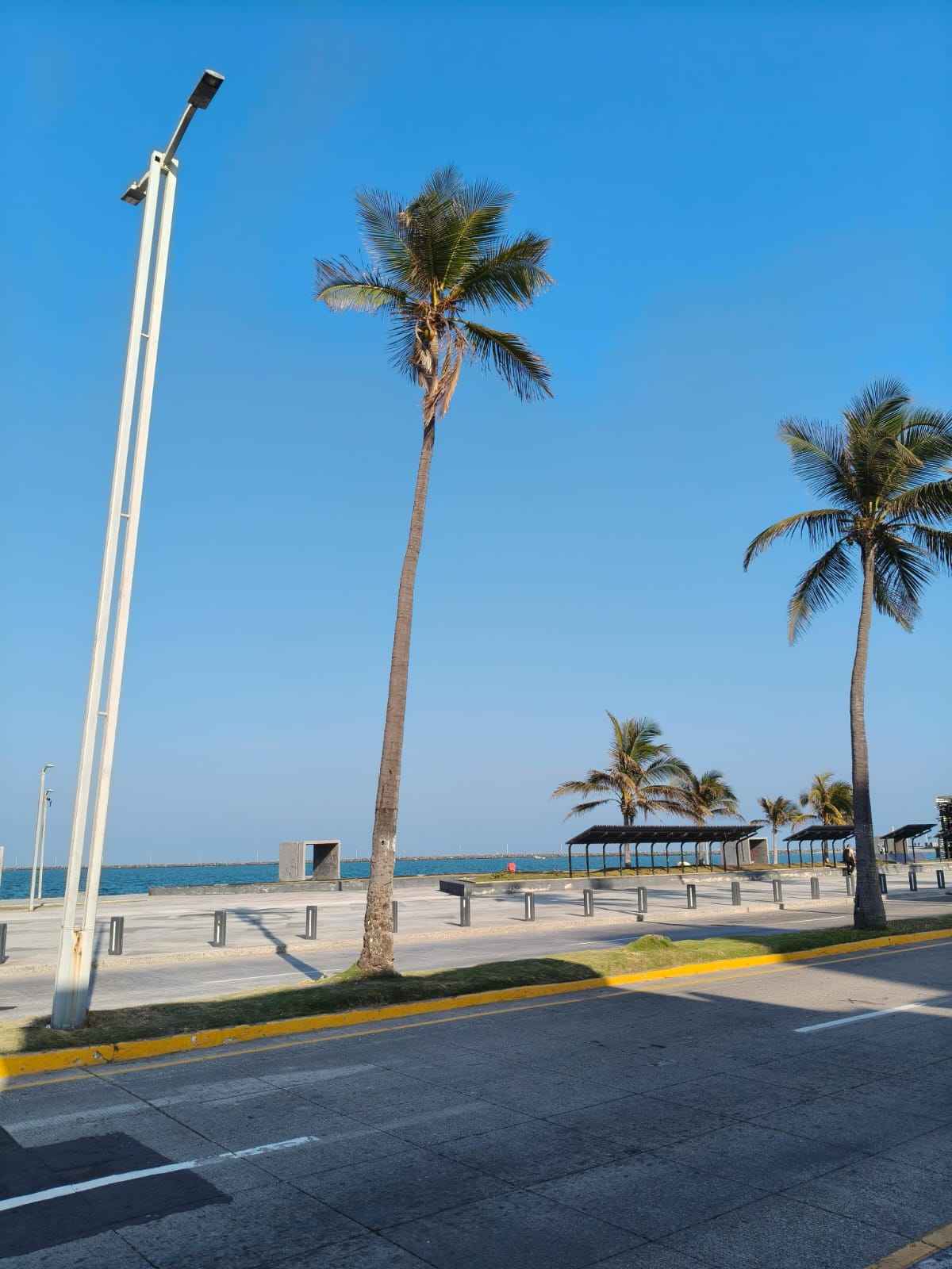
The original image details indicate that the file size is 11 MB, which is more than a tenth of the 100 MB my repository should weigh by the end of Fab Academy.
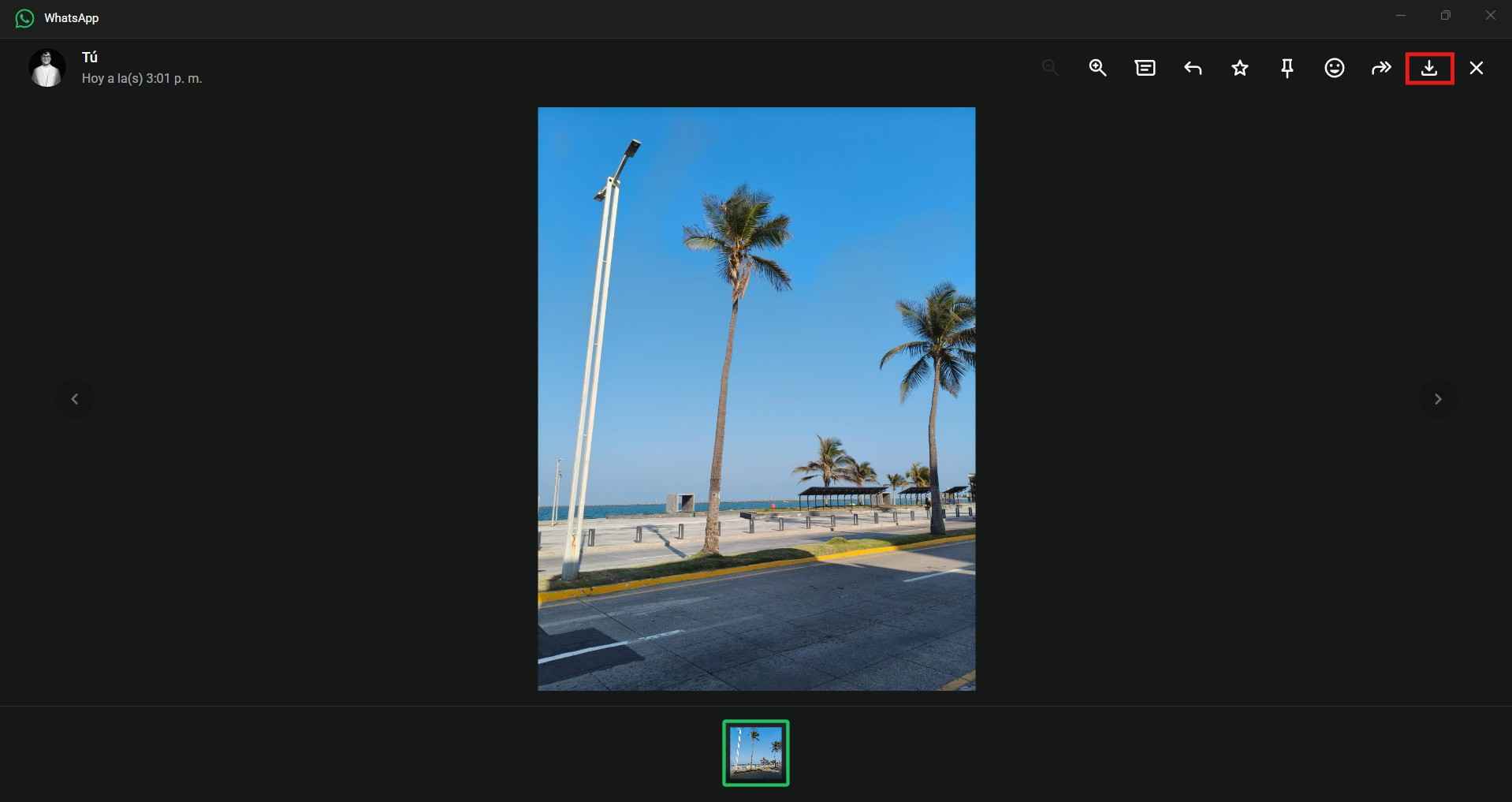
The key to effectively compressing images through WhatsApp is to send them as chat images instead of as files. We can send the picture to ourselves and then open the WhatsApp messaging app on our personal computers to download the image we sent.
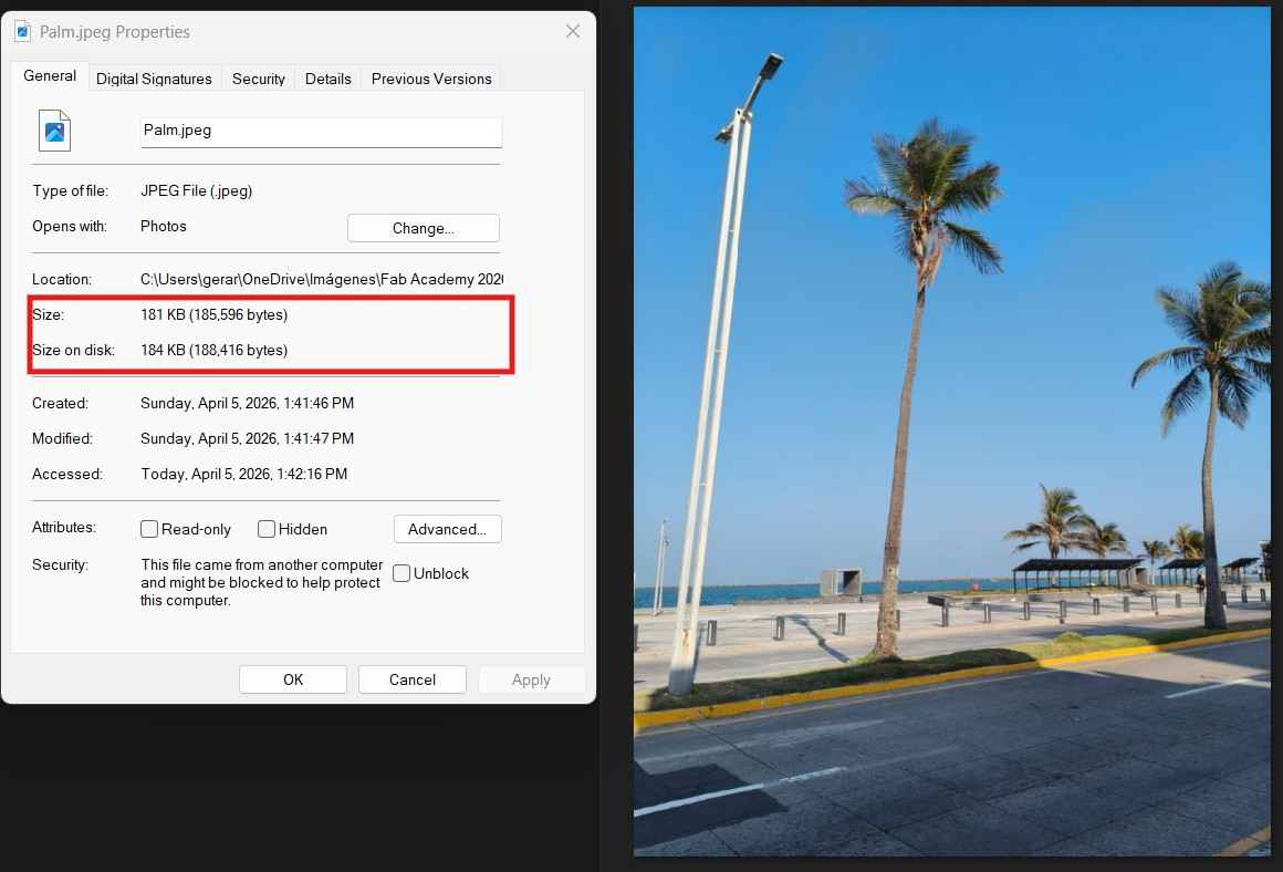
By sending the picture through a WhatsApp chat, the file size decreased from 11 MB to just 181 KB. While this reduction is impressive, the file can still be further compressed using the FabCompress tool.
4.2. Video compression
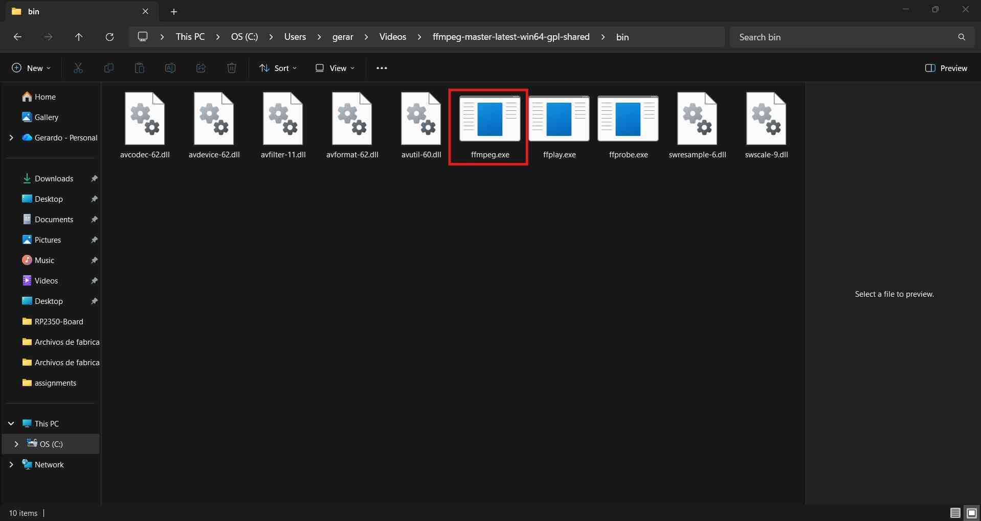
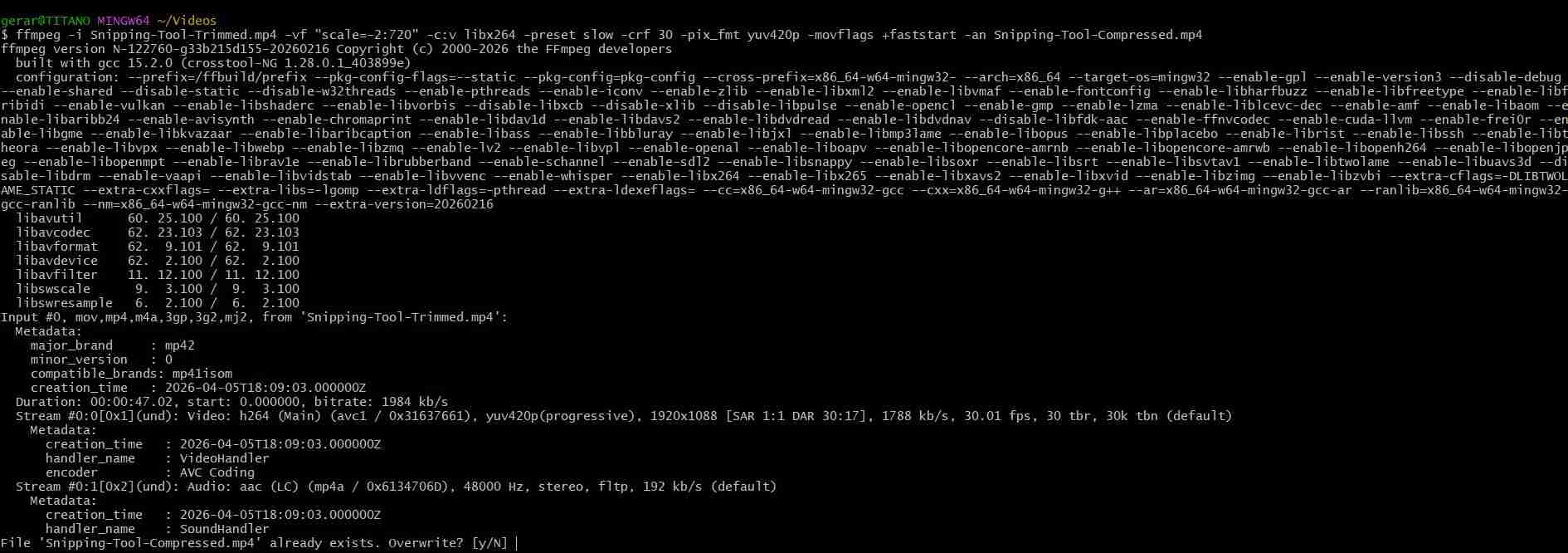
Video compression retains some full frames while mainly focusing on the differences between frames, taking advantage of the similarities that frequently occur among them. Our local instructor, Oliver Ochoa García, suggested using FFmpeg for video compression. FFmpeg stands for Fast Forward Moving Picture Experts Group. FFmpeg is a command-line multimedia engine that reads, converts, compresses, filters, and writes audio/video data using different codecs and containers. You can download the specific version for your operating system by clicking here.
The following are the main FFmpeg components:
- Container: A file format that holds the media streams; examples include MP4, MKV, AVI, and MOV.
- Codec: Method employed to encode and decode audio or video data. Examples of video codecs include H.264, H.265, AV1, and MPEG-4. Examples of audio codecs include AAC, MP3, and Opus.
- Bitrate: Amount of data used per second of audio or video. Bitrate is usually measured in kilobits per second (kbps) or megabits per second (Mbps). A higher bitrate usually means better quality and a larger file size, while a lower bitrate usually means a lower quality and a smaller file size.
- Resolution:The number of pixels in each frame of an image or video; a higher resolution means more detail and more pixels to encode, resulting in larger files or a higher required bitrate. Resolution represents how many pixels exist, while bitrate is about how much data is used to represent them. Examples of resolution include 1280 × 720 = 720p, 1920 × 1080 = 1080p, and 3840 × 2160 = 4K.
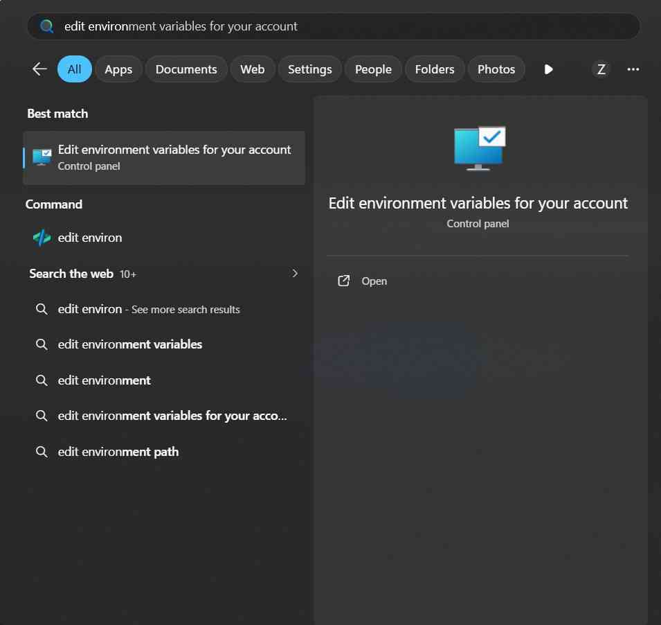
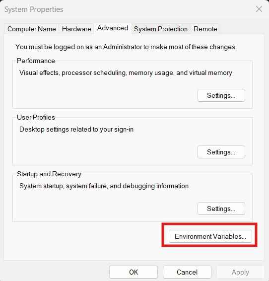
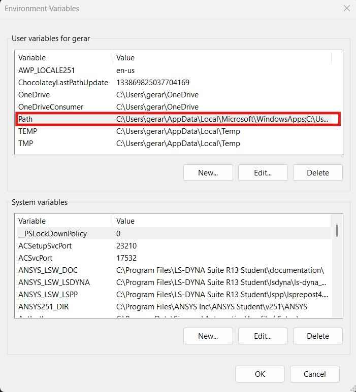
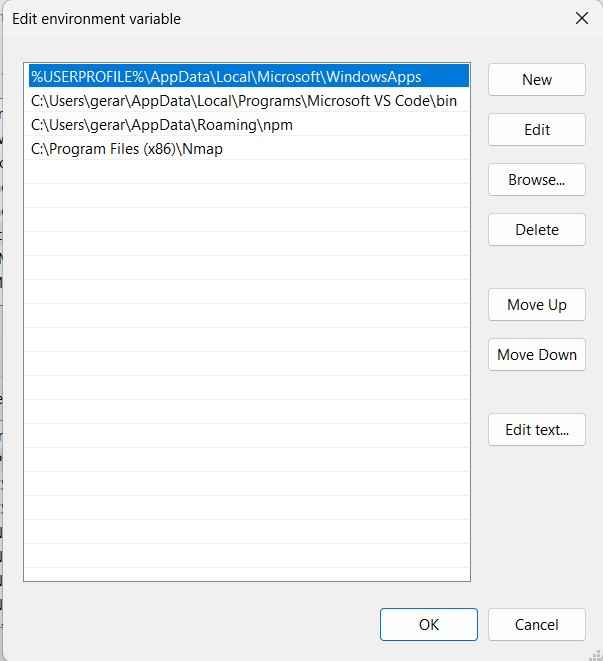
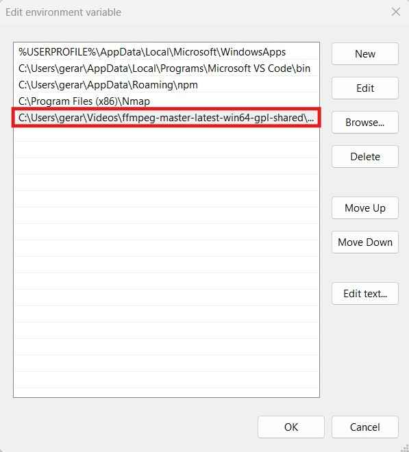
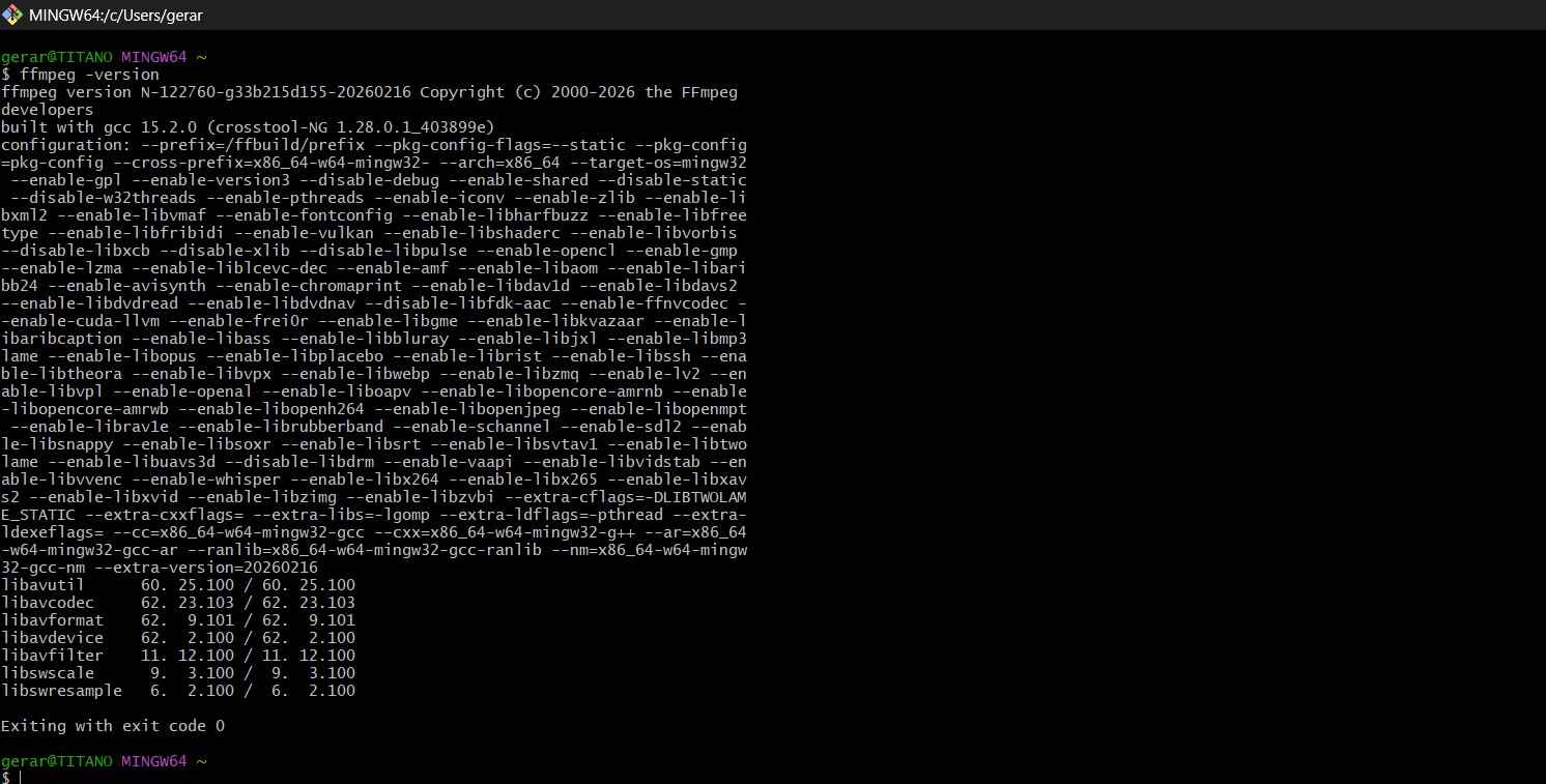
After downloading and decompressing the folder containing the FFmpeg tool, it is beneficial to add the FFmpeg folder to the PATH. The PATH is an environment variable that stores a list of directories where the operating system looks for executable programs. This addition simplifies the execution of inline commands when using FFmpeg.
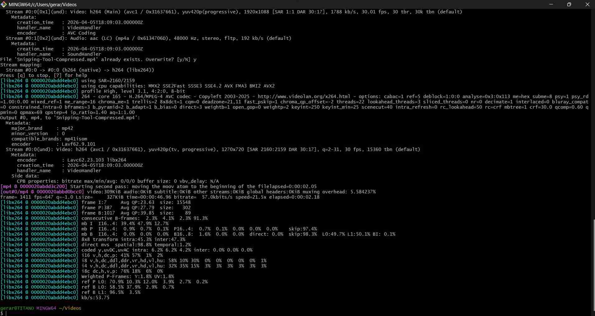
ffmpeg -i input.mp4 -vf "scale=-2:720" -c:v libx264 -preset slow -crf 30 -pix_fmt yuv420p -movflags +faststart -an output_new.mp4
Reflection
What went well, what was hard, what you’d do differently.