Week 13: Moulding and Casting
In this week, we learned how to design, machine, and use molds for moulding and casting processes.
Before starting
Moulding and Casting is a manufacturing process in which a material is shaped by using a mold or cavity to obtain a specific form. In general, the process consists of creating a negative shape (the mold) and then pouring or placing another material inside it to produce a final piece, known as the casting. This technique is widely used because it allows the creation of complex, precise, and repeatable shapes with high detail and consistency.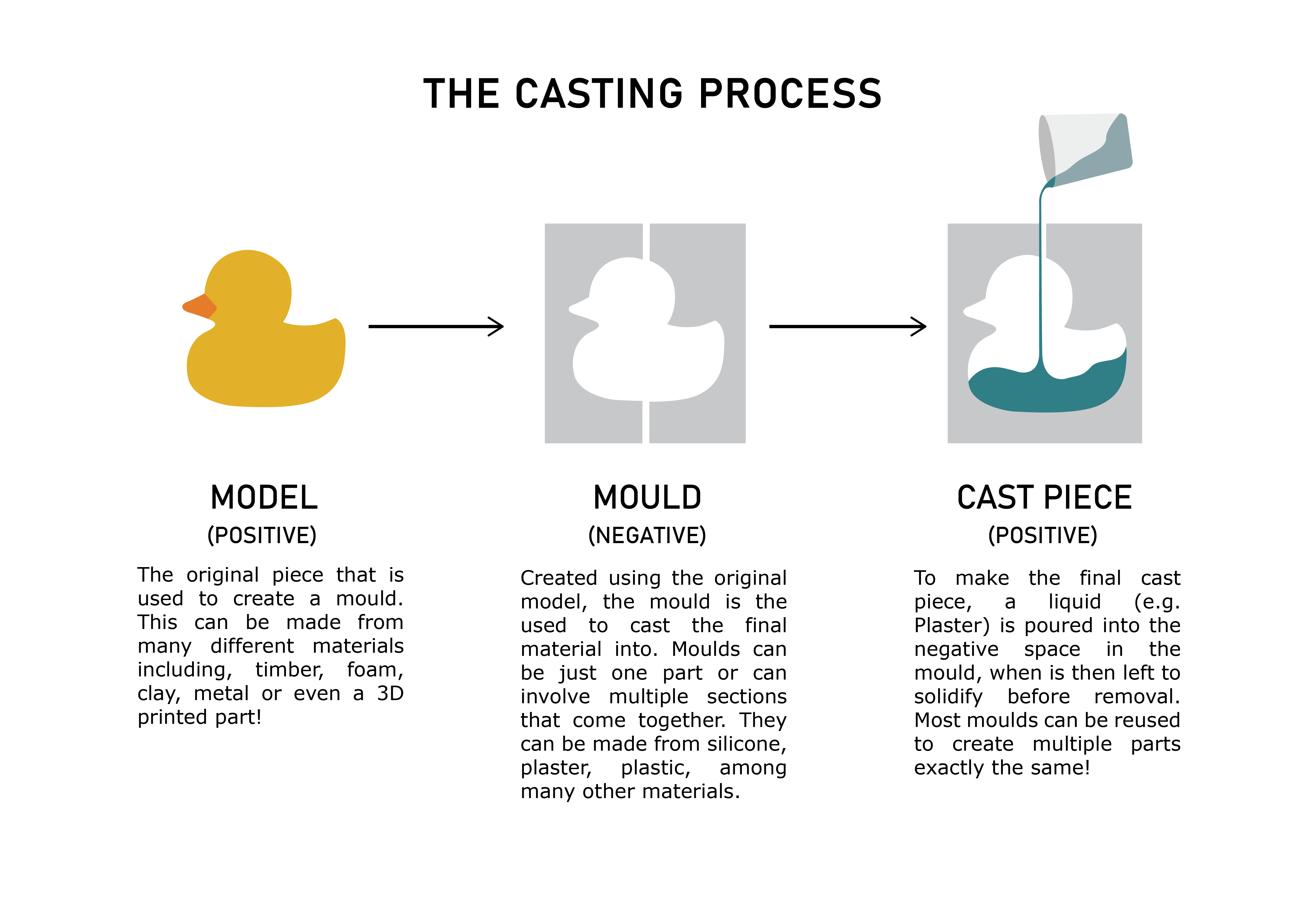
Molds are often created in alternating layers or stages, depending on the desired result. A common approach is to start with a rigid mold, continue with a flexible or soft mold, and finish again with a rigid outer shell for structural support. The opposite process can also be applied, beginning with a soft layer, followed by a rigid reinforcement, and ending with another flexible layer. This combination allows the mold to maintain its shape while still being flexible enough to release the final object without damage.
A wide variety of materials can be used in moulding and casting, including metals, resins, plastics, silicone, plaster, wax, and even chocolate. The selected material depends entirely on the intended purpose of the mold or final product. For example, metal molds are commonly used for industrial mass production due to their durability, while silicone molds are preferred for artistic, medical, and food-related applications because of their flexibility and detail reproduction.
Another important aspect of moulding and casting is prototyping and product development. Engineers, artists, and manufacturers frequently use these techniques to quickly create prototypes, replacement parts, decorative objects, medical prosthetics, and custom components. Modern technologies such as 3D printing are also commonly combined with moulding and casting, where a 3D-printed object serves as the master model used to create the mold.
Overall, moulding and casting are essential manufacturing techniques because they enable efficient production, high precision, material versatility, and the ability to replicate objects multiple times with consistent quality.
For further information about this topic, please consult this week’s group page.
Mold Design
Mold design
Blender is a 3D design and modeling software that allows users to create, edit, sculpt, animate, and prepare digital objects for manufacturing processes such as 3D printing and CNC machining. One of its most useful features for moulding and casting is the use of boolean operations, which make it possible to combine, subtract, or intersect geometries in order to create precise molds and complex shapes.
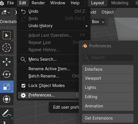
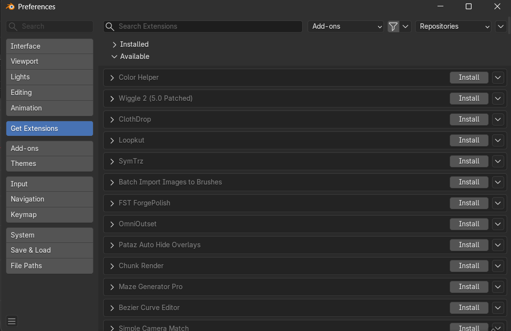
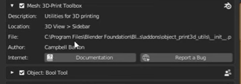
Before starting the project, it is necessary to install several add-ons that enable boolean tools and exporting objects as STL or mesh files, such as the 3D Print Toolbox.
To install them, go to Edit → Preferences → Get Extensions and search for the required libraries.
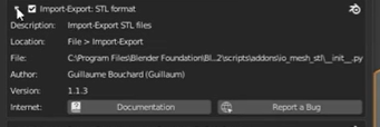
To install them, go to Edit → Preferences → Get Extensions and search for the required libraries.
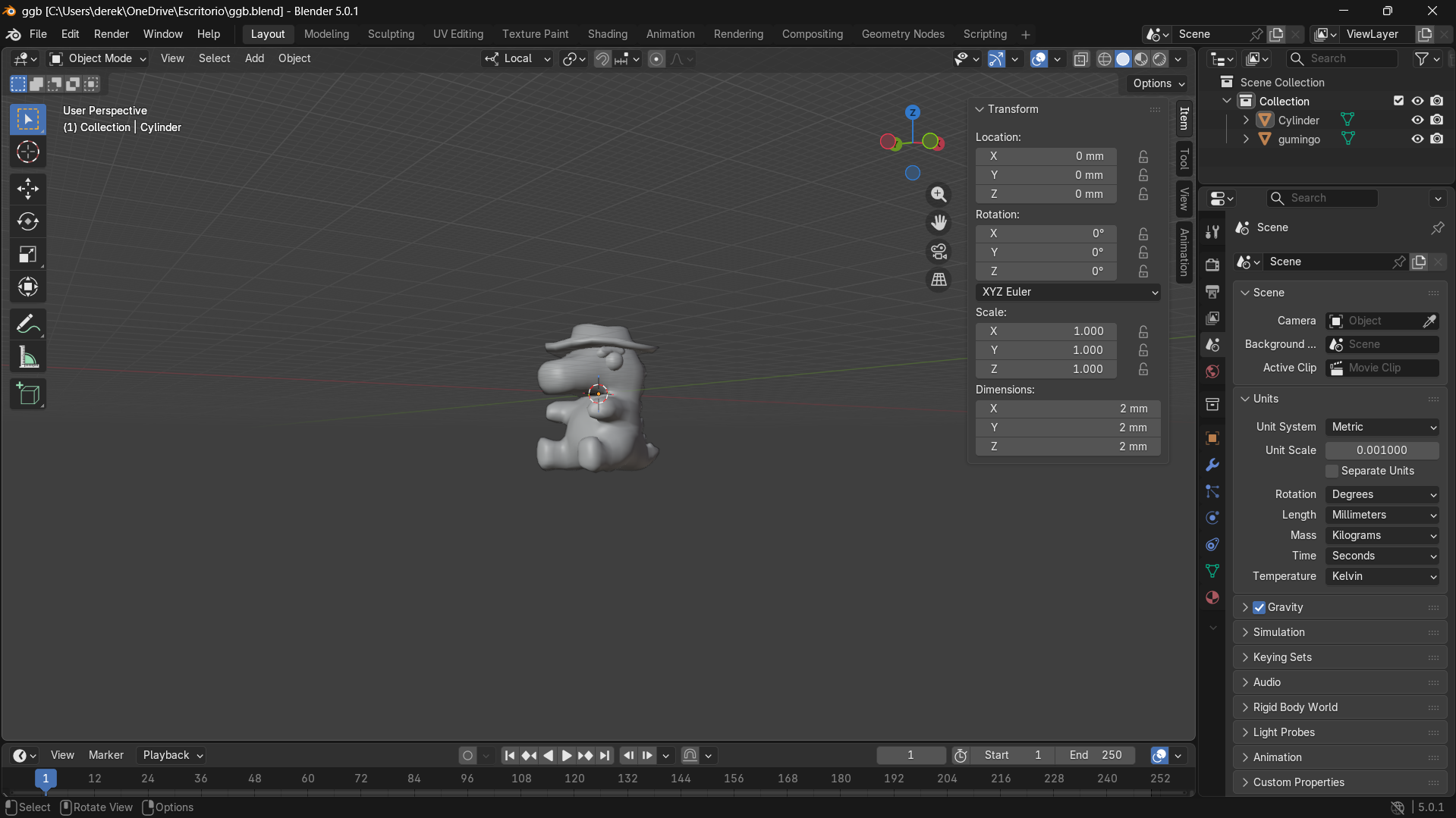
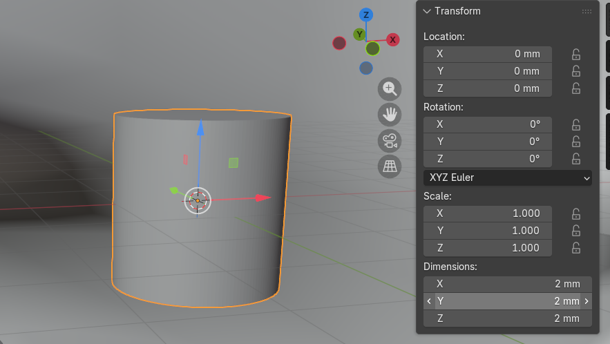
Once this is completed, the object that will be used to create the mold is imported and scaled to the desired final size in millimeters using the Dimensions tool.
Building the mold geometry
To import a 3D geometric shape into the workspace, press Shift + A. From there, different geometries such as cubes, cylinders, and spheres can be added directly into the scene.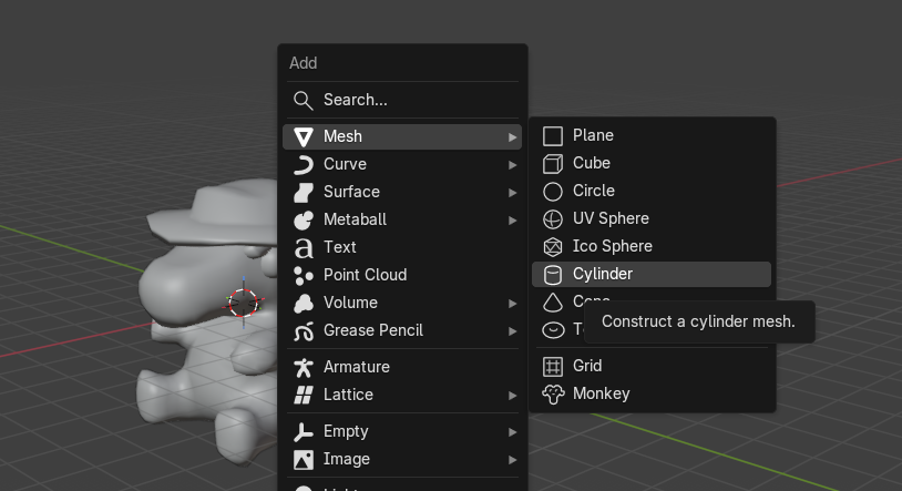
Two additional inner cubes were then added and sized to fit inside the outer cubes, leaving exactly 3 mm of wall thickness on all sides. This inner volume defines the hollow cavity of each mold half, similar to the concept of Han Solo frozen in carbonite . The figure becomes embedded inside a hollow cube shell.
The character STL was duplicated using Shift + D so that one copy could be used for each mold half independently.
Boolean operations
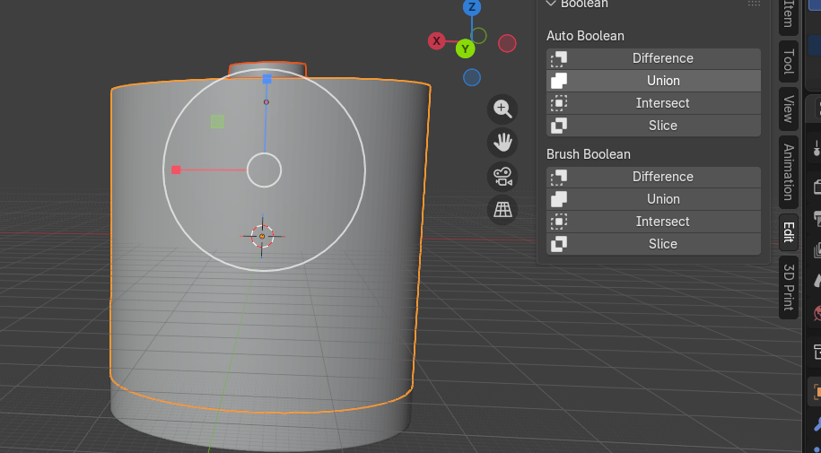
To perform a boolean operation, a modeling process used to combine or cut objects using mathematical geometry operations , select the object and open the edit menu on the right side panel.
In the Auto Boolean section, geometries can be joined, subtracted, or intersected depending on the desired result:
- Union: merges two objects into one solid volume.
- Difference: subtracts one object from another, carving out its shape.
- Intersect: keeps only the overlapping volume of both objects.
For this project, the goal is to create a rigid counter-mold, then produce a flexible silicone mold, and finally obtain a rigid final object such as a candle or soap.
Using boolean operations together with imported geometries, the following mold design was obtained.
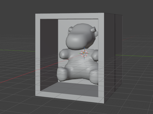
Using boolean operations together with imported geometries, the following mold design was obtained.
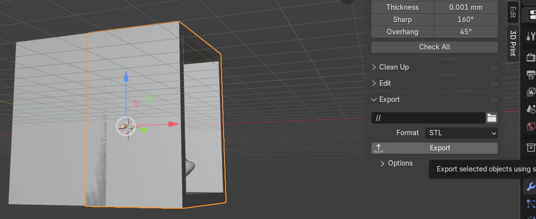
To export the file, open the 3D Print menu, select the STL option, and click Export.
UltiMaker Cura Overview
UltiMaker Cura is a slicing software used to prepare 3D models for filament (FDM) printers.In simple terms, Cura converts a 3D model (STL) into G-code, which is the language the 3D printer understands. It allows users to configure printing parameters such as layer height, speed, temperature, supports, and adhesion settings.

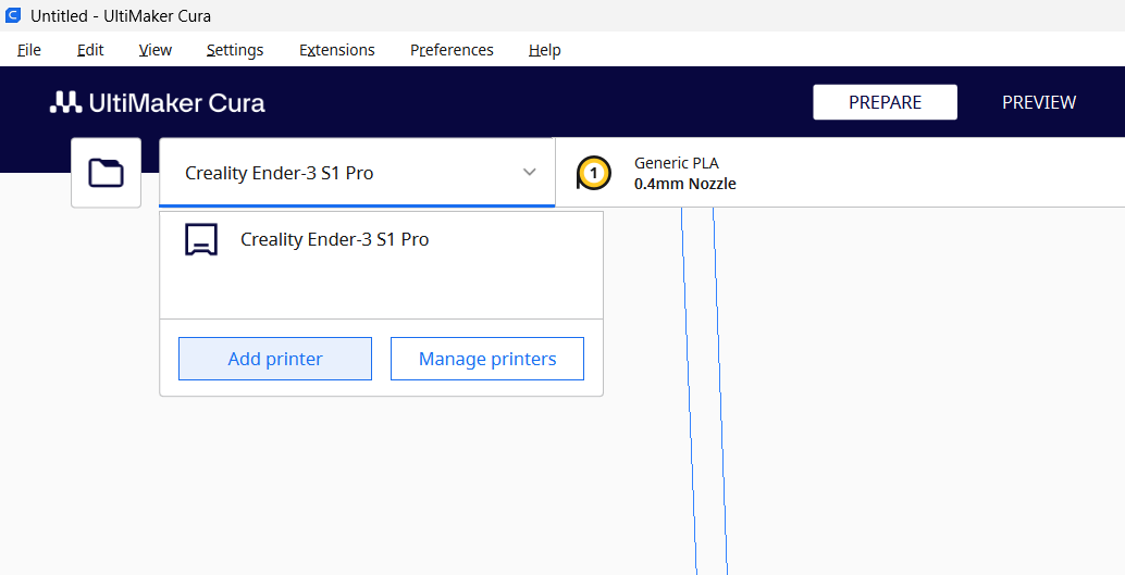
1- Selecting the Printer
Once the application is open, the first step is to select or add a printer:- Click on the top tab and select Add Printer.
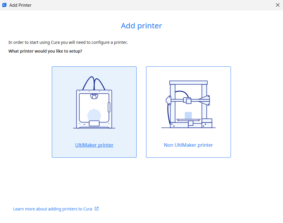
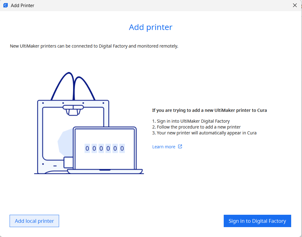
- Choose whether your printer belongs to the Ultimaker group or is a non-Ultimaker machine.
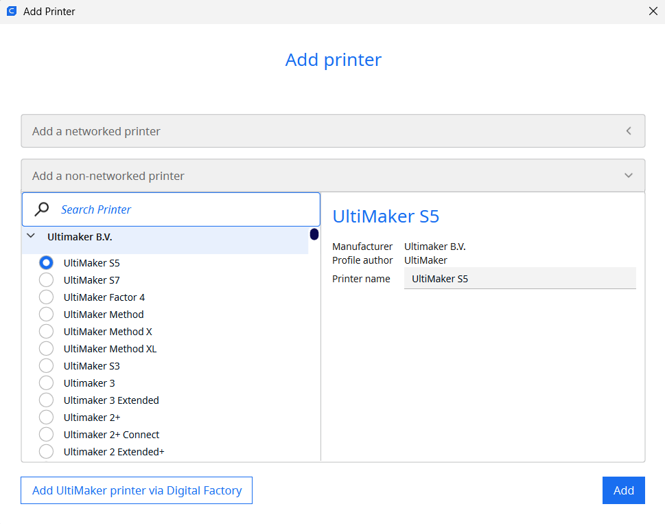
- Finish by adding your local printer from the list provided in the menu.
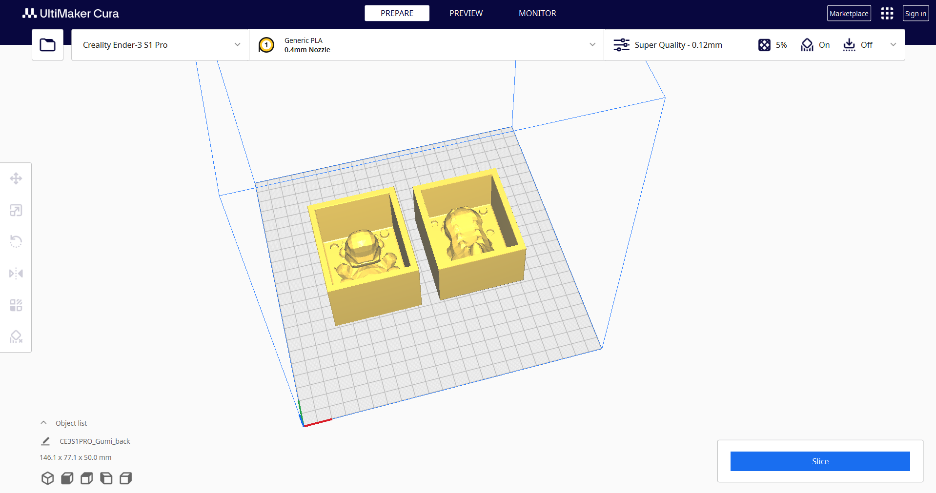
2- Importing the STL File
After setting up the printer:- Import the STL file from the Files tab
- Click the folder icon located in the upper toolbar.
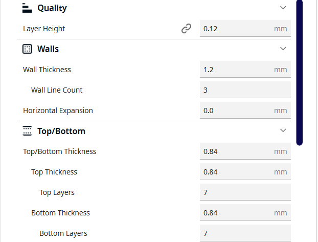
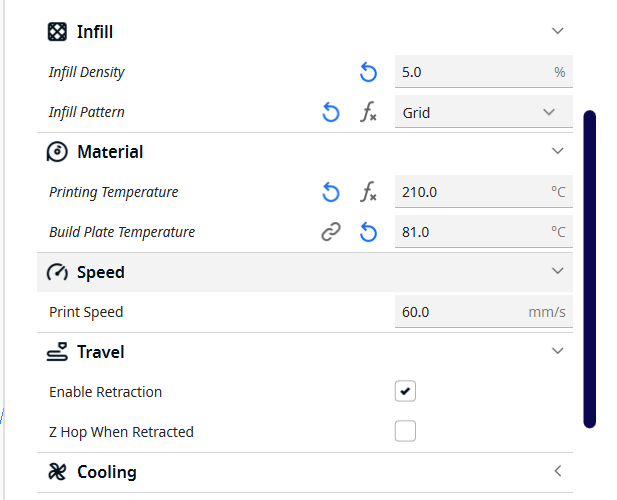
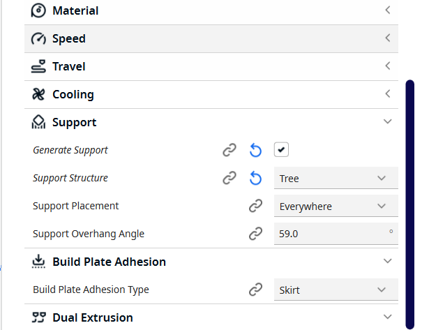
Parameters that I use:
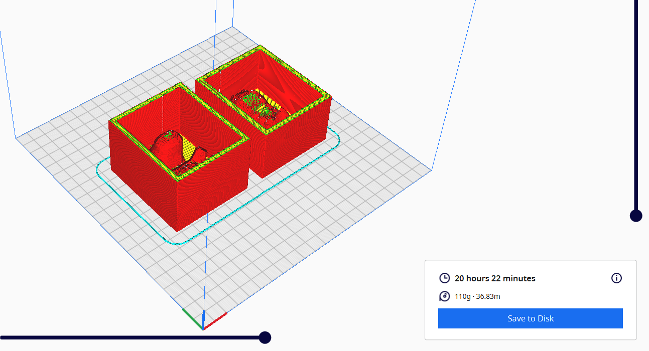
4- Slicing and Preview
Once the parameters are configured:- Click the Slice button located at the bottom of the settings panel.
- Click Preview to visualize how the printer will build the object layer by layer.
- Click Save to Disk.
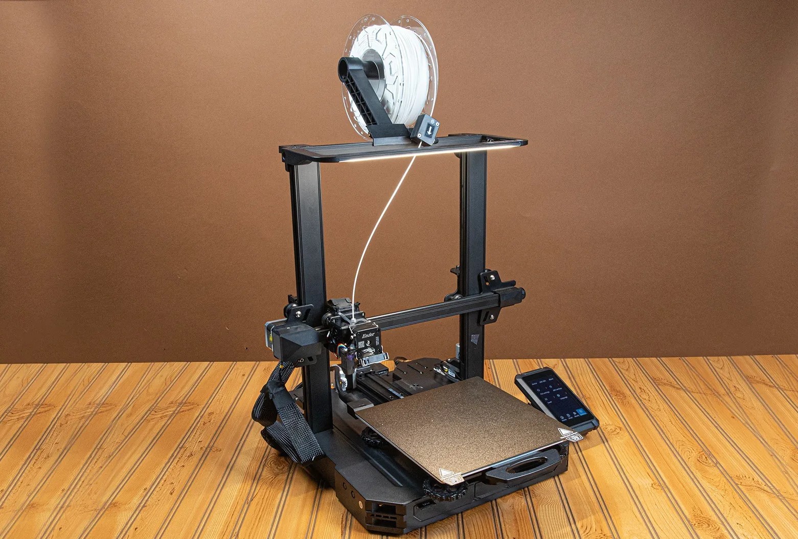
In this case, the Creality Ender-3 S1 Pro 3D printer was used.
We start by taking the SD card included with the printer.
To access it from the computer, we use an SD to USB-C adapter (in this case), allowing us to transfer files easily.
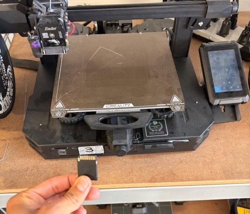
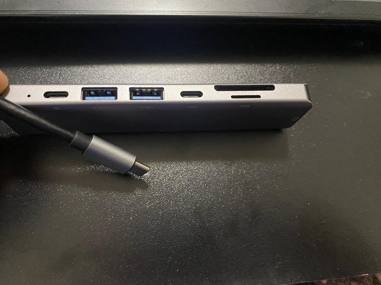
Once the G-code file has been saved onto the SD card, we insert it back into the printer.
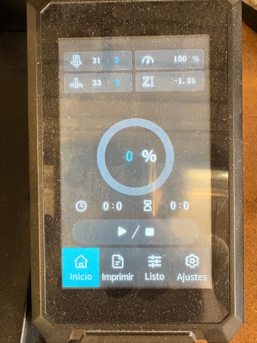
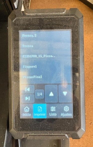
On the printer’s touchscreen interface, we navigate to the “Print” menu.
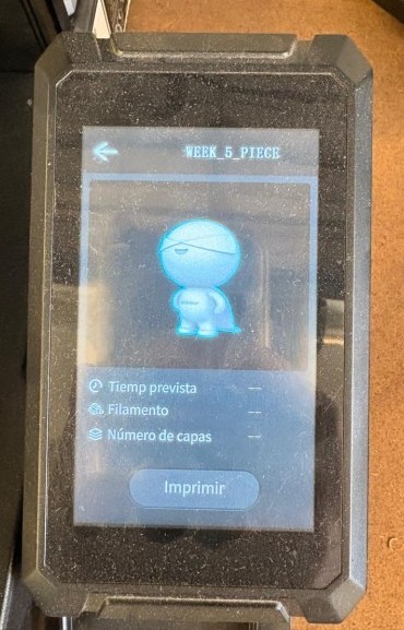
Inside this menu, we search for the file using the name previously assigned in the slicer software.
After selecting the file, we simply press Start
On the printer’s touchscreen interface, we navigate to the “Print” menu.
Inside this menu, we search for the file using the name previously assigned in the slicer software.
After selecting the file, we simply press Start
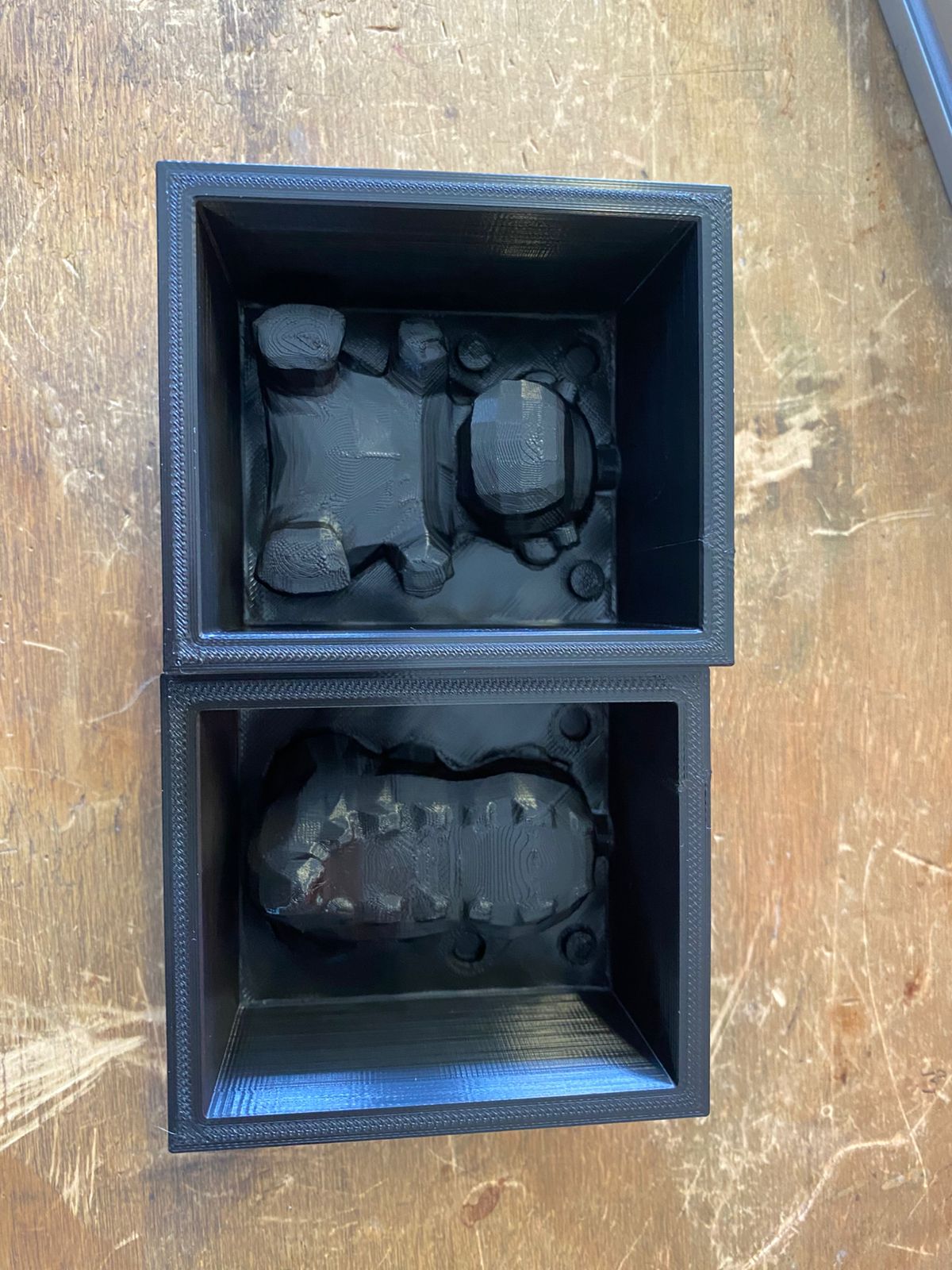
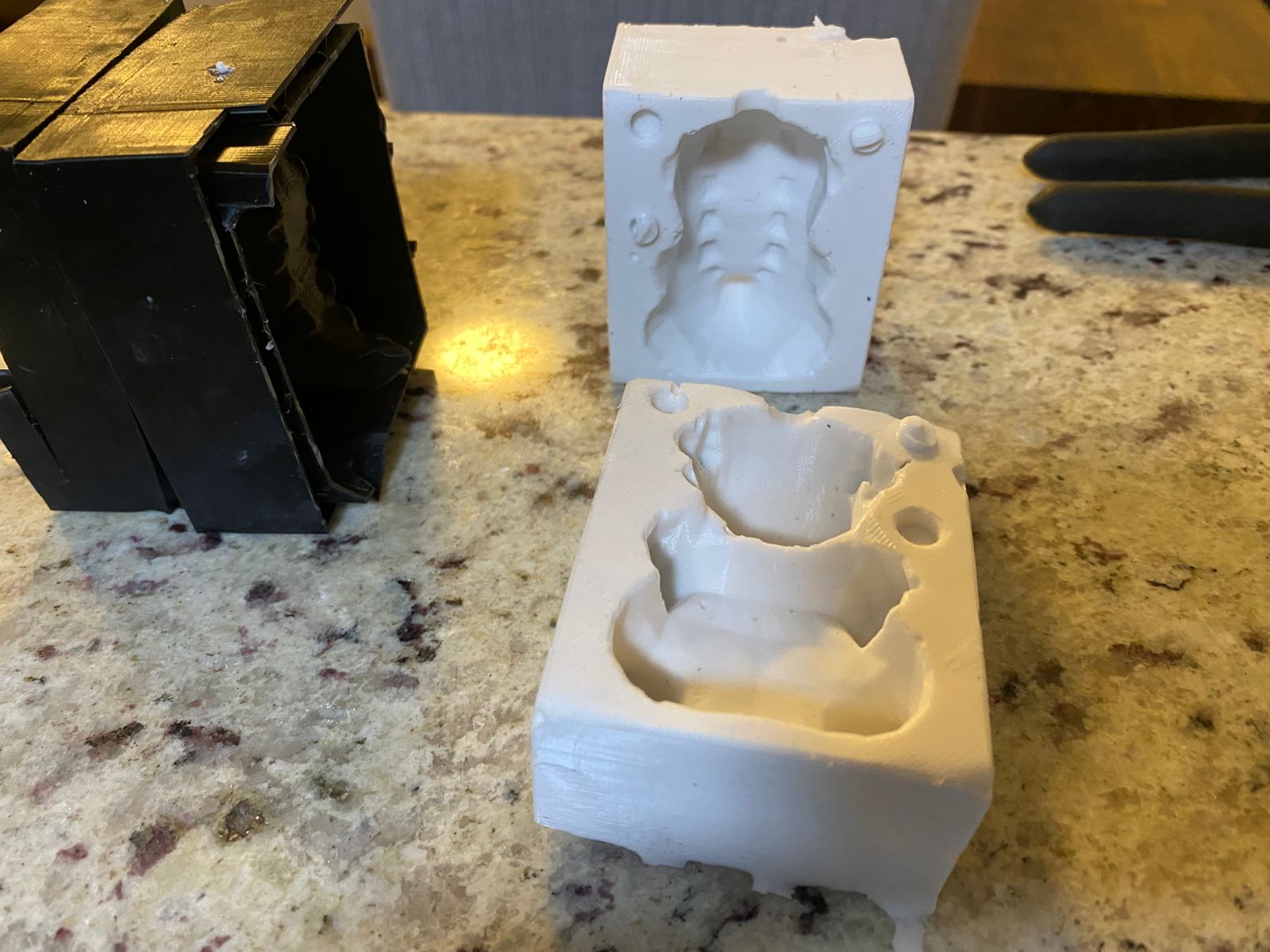
The final printed mold looks as follows.
Design Considerations
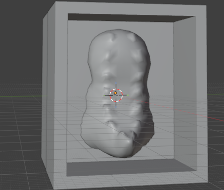
When designing a mold for an organic figure like this one, undercuts must be carefully analyzed before defining the parting plane. An undercut is any geometry that would prevent the cast piece from being released from the mold without tearing or breaking it.
In this case, undercuts were present due to the rounded and irregular volume of the figure. The orientation of the parting plane is critical:
- Splitting the mold along the XY plane (where X points forward, Y points to the side, and Z is the vertical height) creates a horizontal cut. In this orientation, the overhanging geometry of the figure locks inside the mold cavity, making demolding difficult or impossible without damaging the piece.
- Splitting the mold along the XZ plane instead — cutting the figure vertically into a front half and a back half — resolves the undercut problem. In this orientation the two mold halves separate cleanly along the natural silhouette of the figure, allowing the cast piece to release without interference.
Mold Preparation
With the rigid mold completed, the next step is preparing the silicone mold.
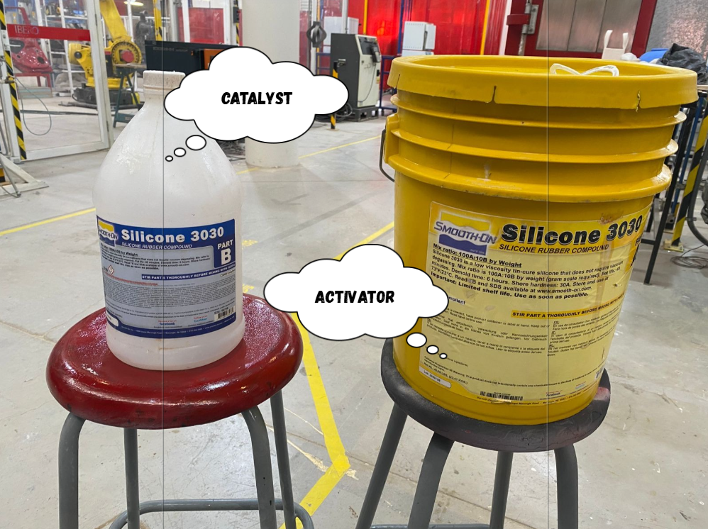
The silicone consists of two components: the silicone base resin and the activator/catalyst, which are mixed in a 10:1 proportion.
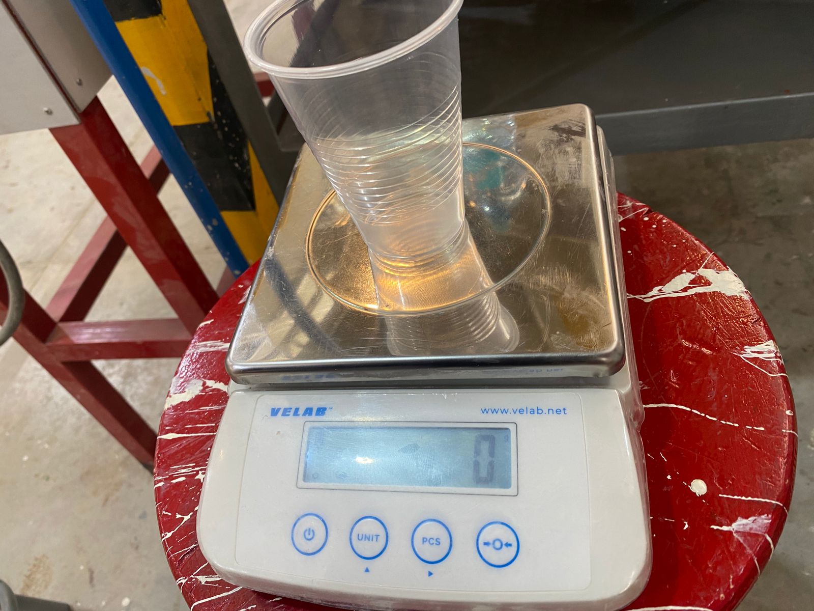
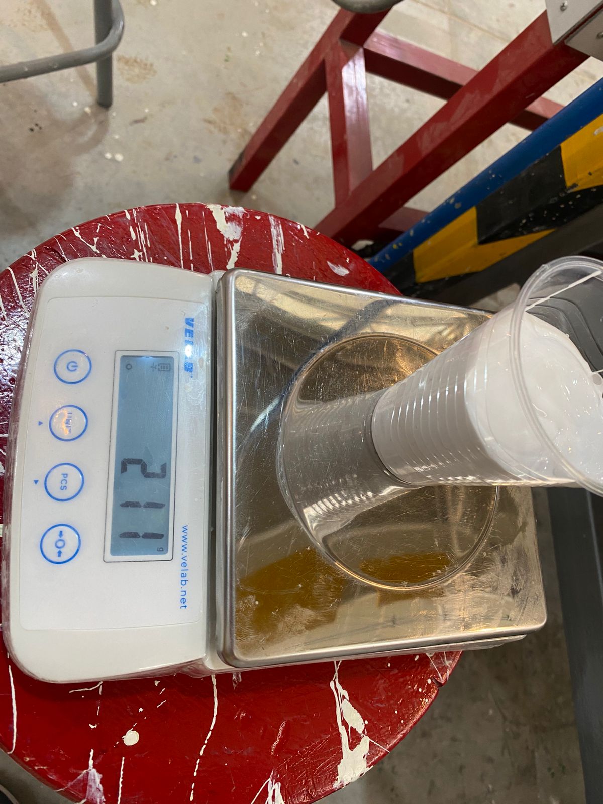
 And then, the procedure may vary depending on the scale model, but it generally consists of taring or zeroing the scale before taking measurements. The measuring cup is placed on the scale, and the Tare or Set button (available on most digital scales) is pressed to reset the displayed weight to zero. This ensures that only the weight of the material being added is measured, providing more accurate and reliable results during the mixing process.
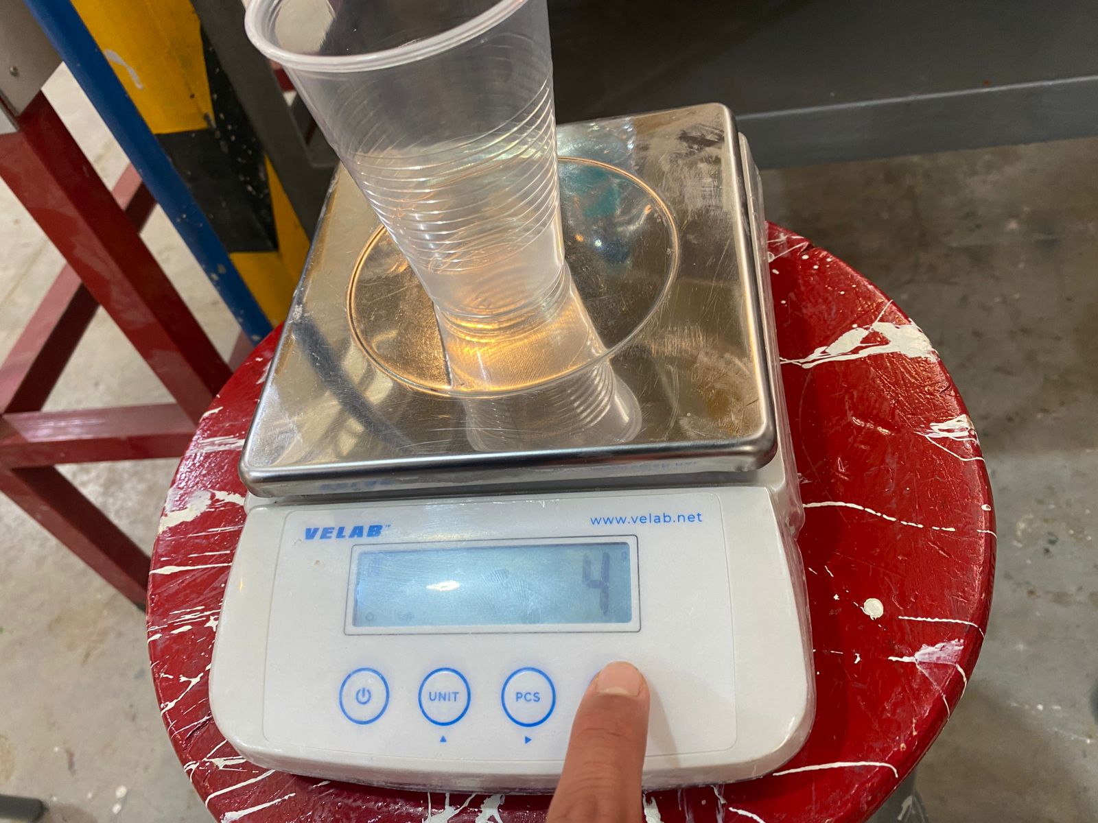
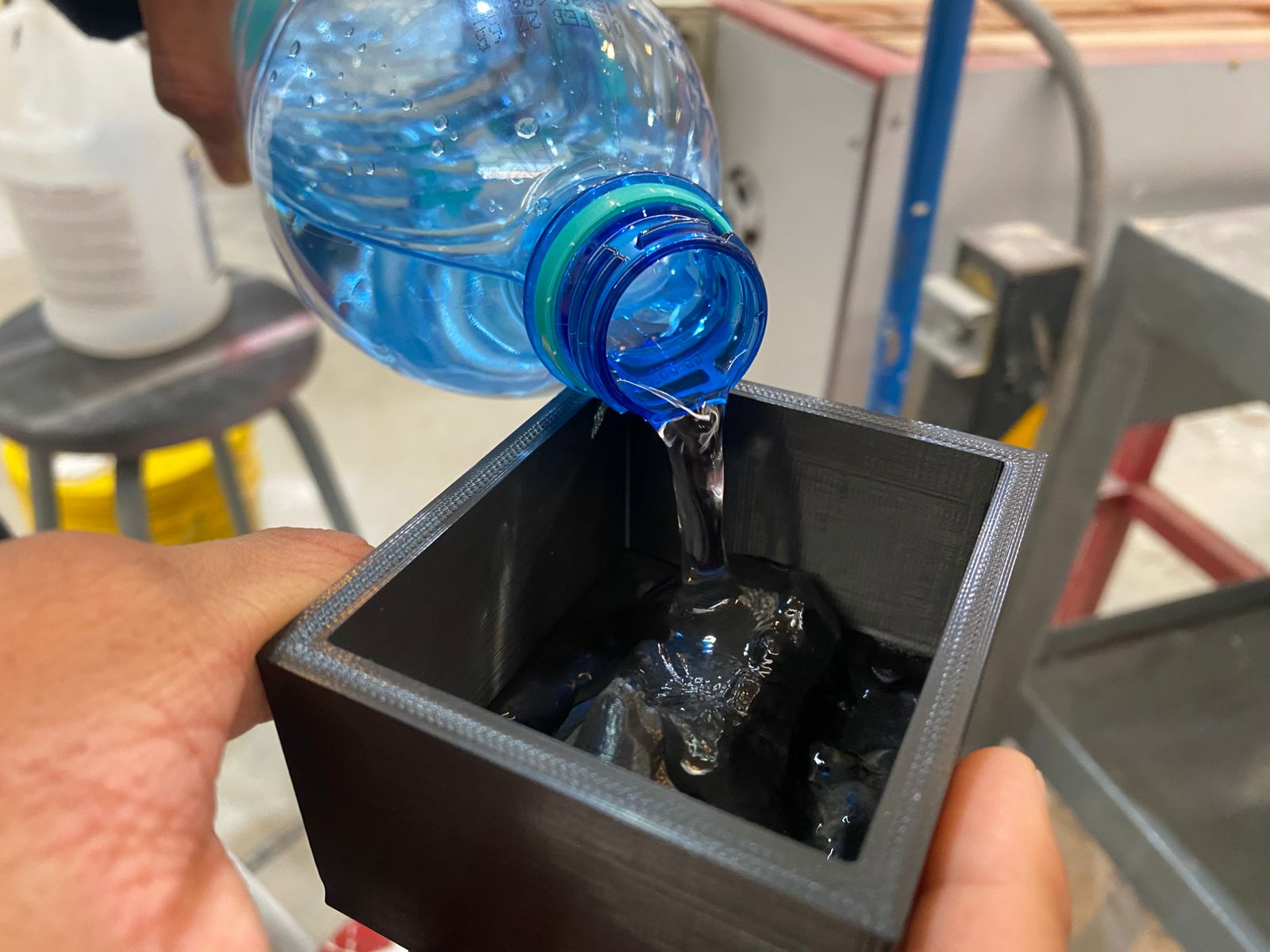
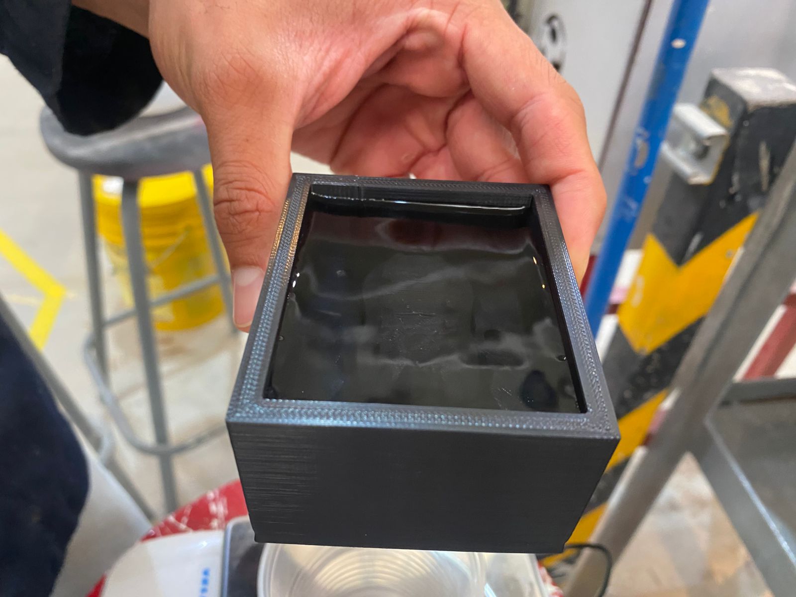
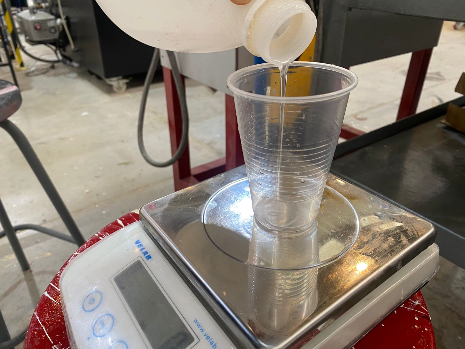
To calculate the required amount of silicone, the rigid mold is first filled with water until the piece is completely covered. This allows the total mold volume to be measured.
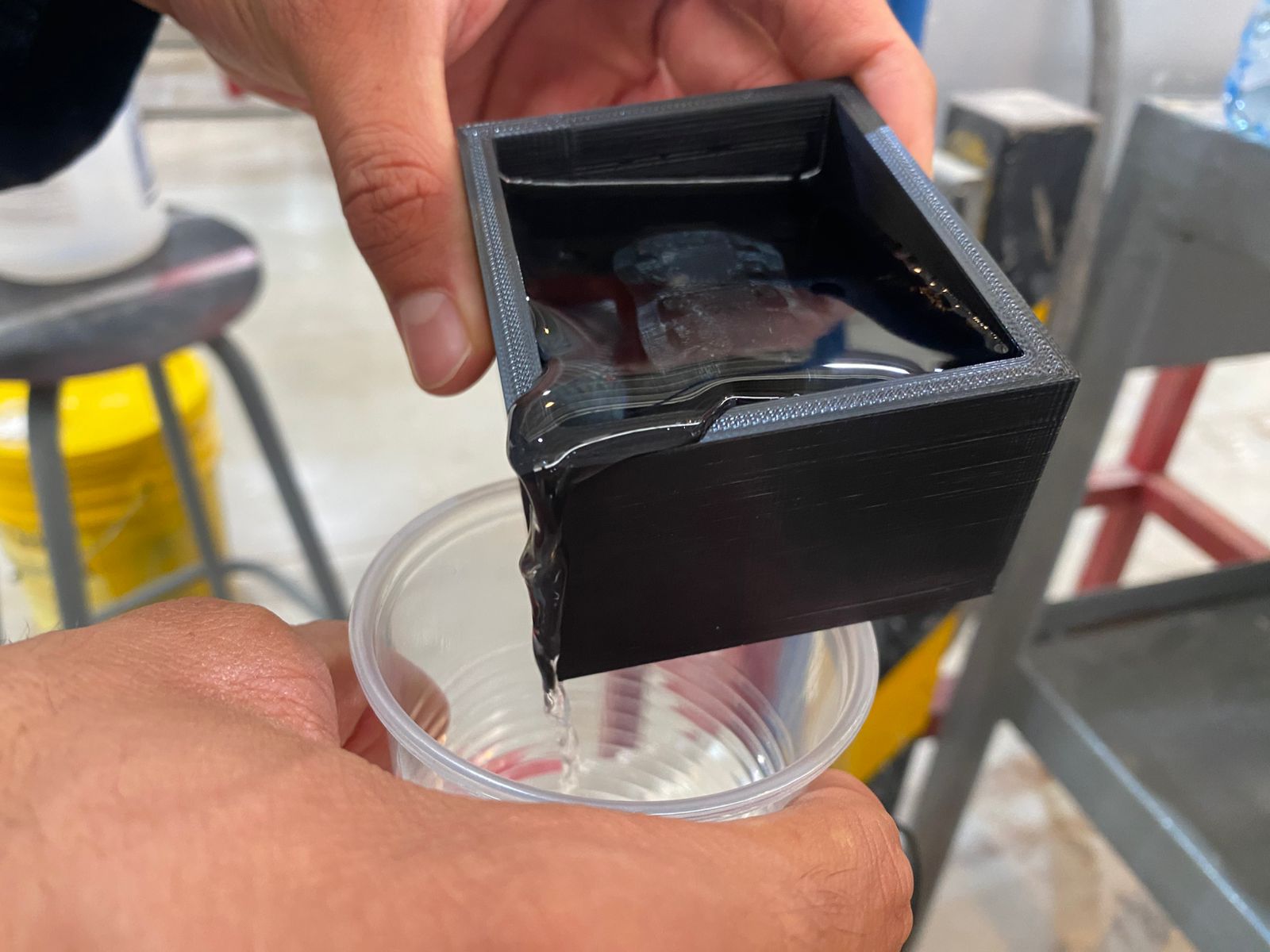
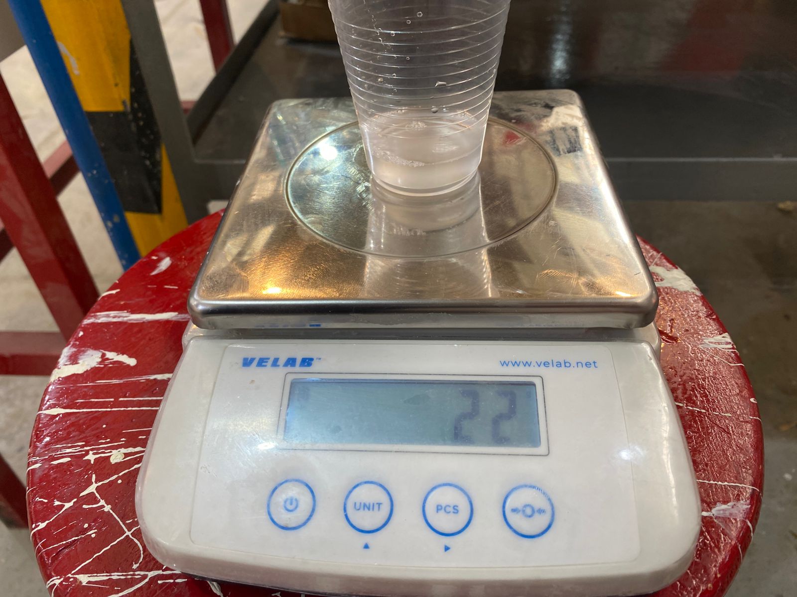
 The water is then poured into a cup placed on a previously tared scale and weighed.
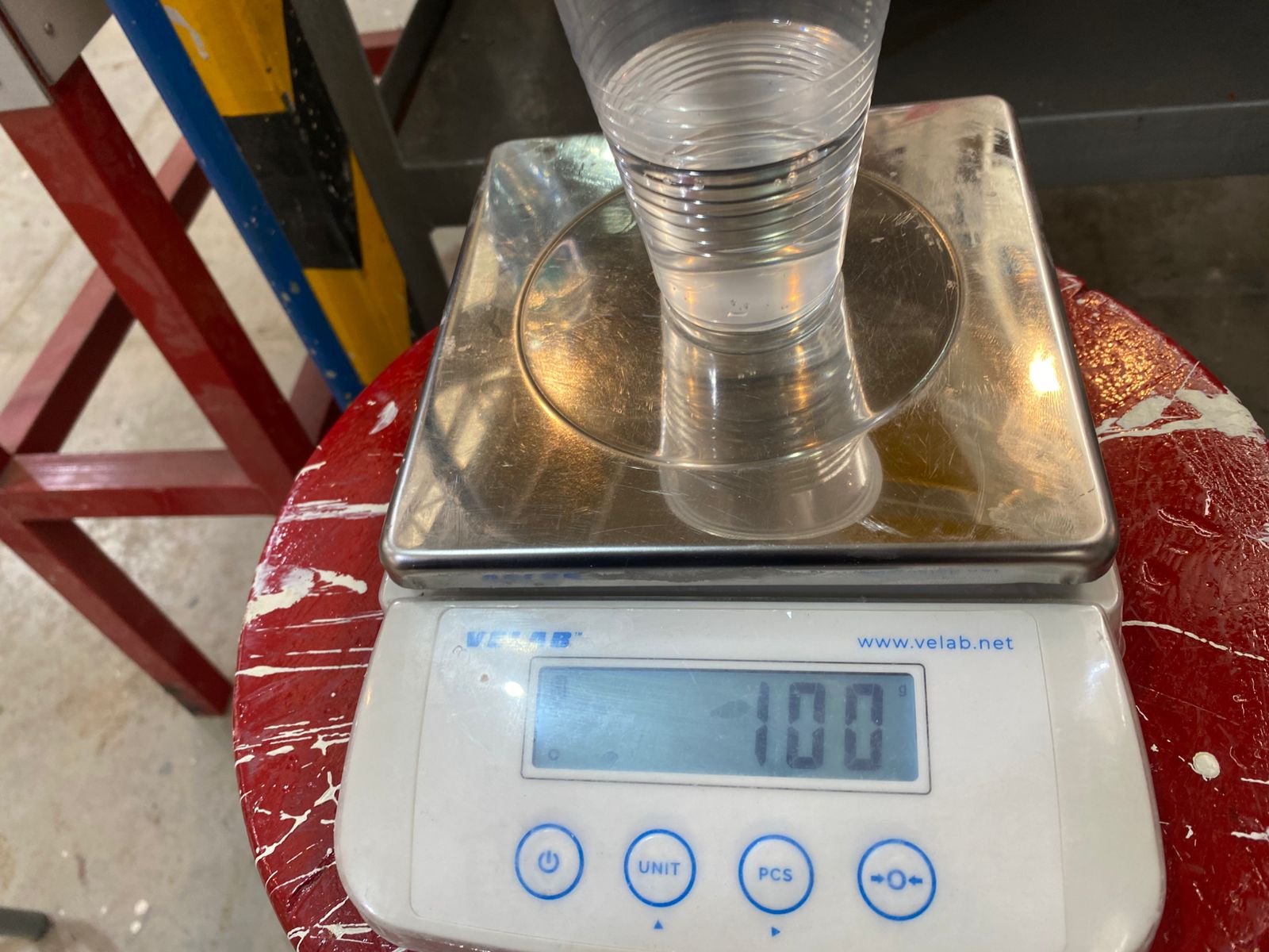
In this case, both molds have an approximate volume of 100 mL each, meaning around 200 mL of silicone ±20 mL and 20 mL of catalyst ±2 mL are required, considering that 1 g is approximately equal to 1 mL.
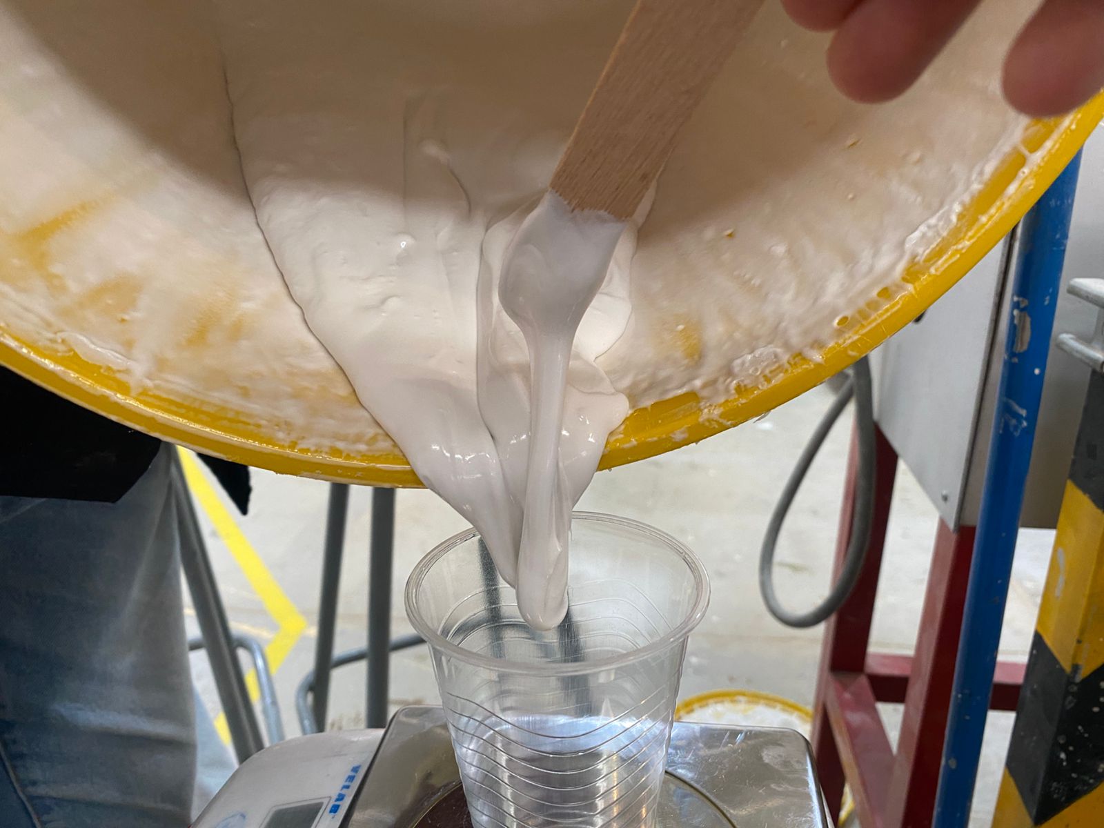
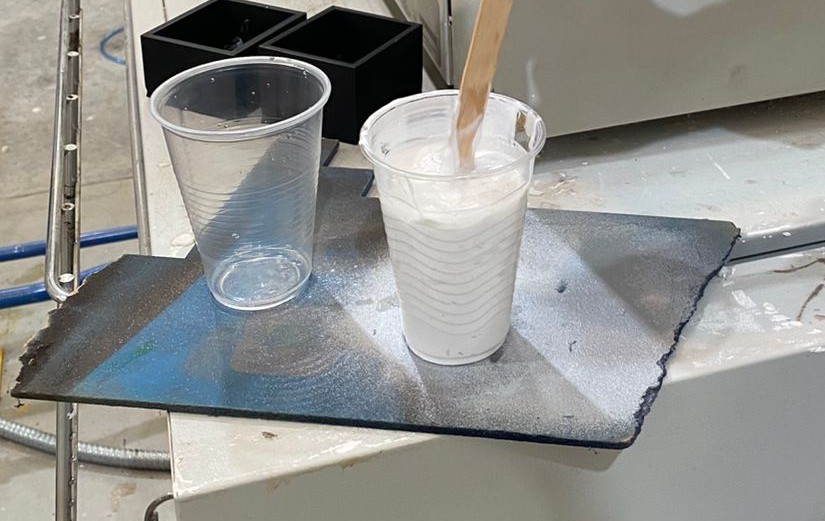
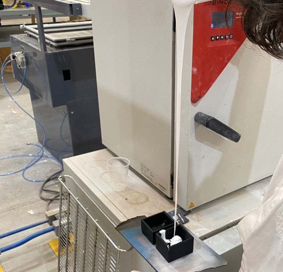
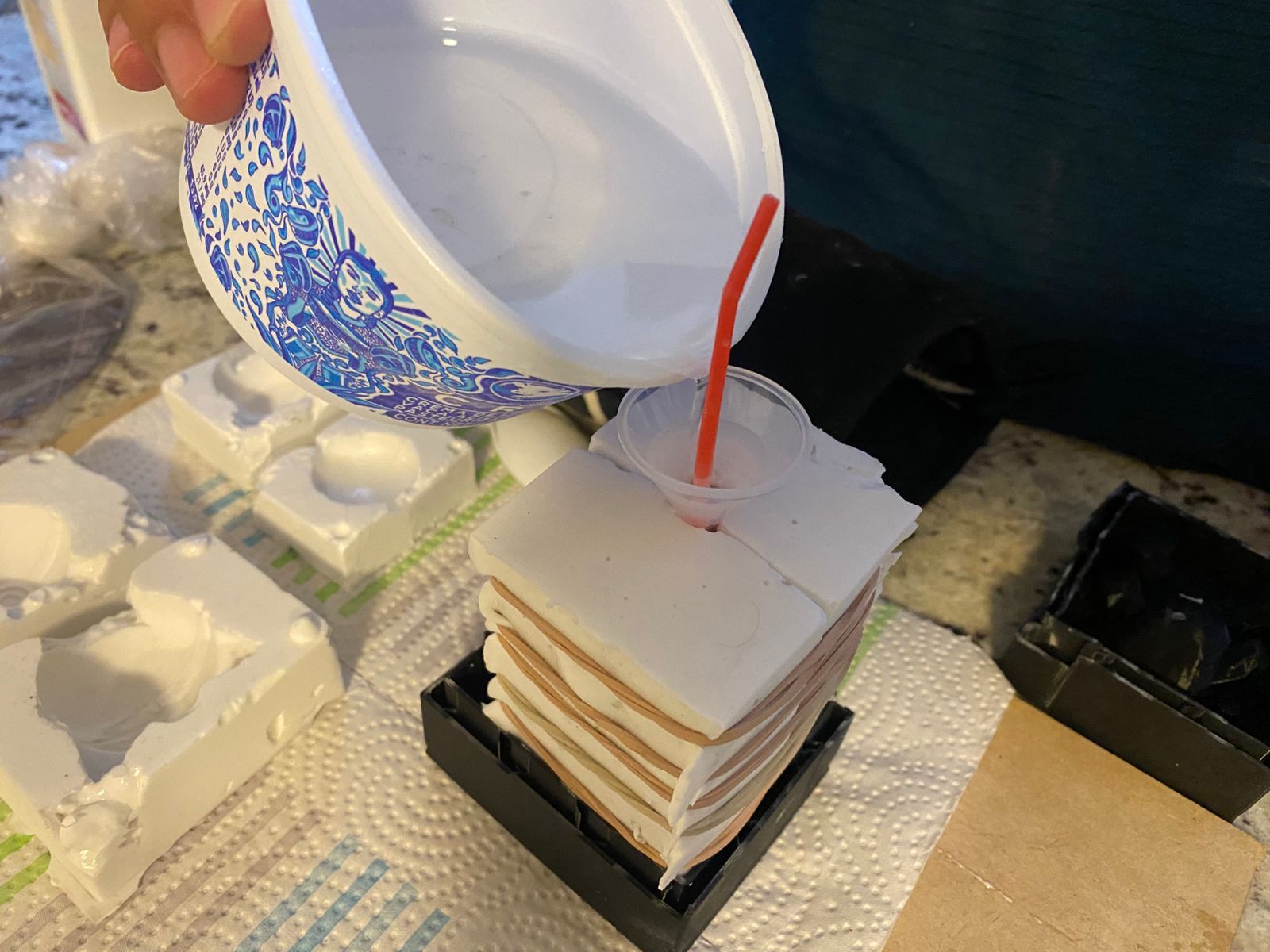
Once the correct proportions are measured, both liquids must be mixed quickly and carefully. The mixture is then poured from a reasonable height into the mold in order to minimize the formation of air bubbles, which could create imperfections or empty spaces inside the final mold.
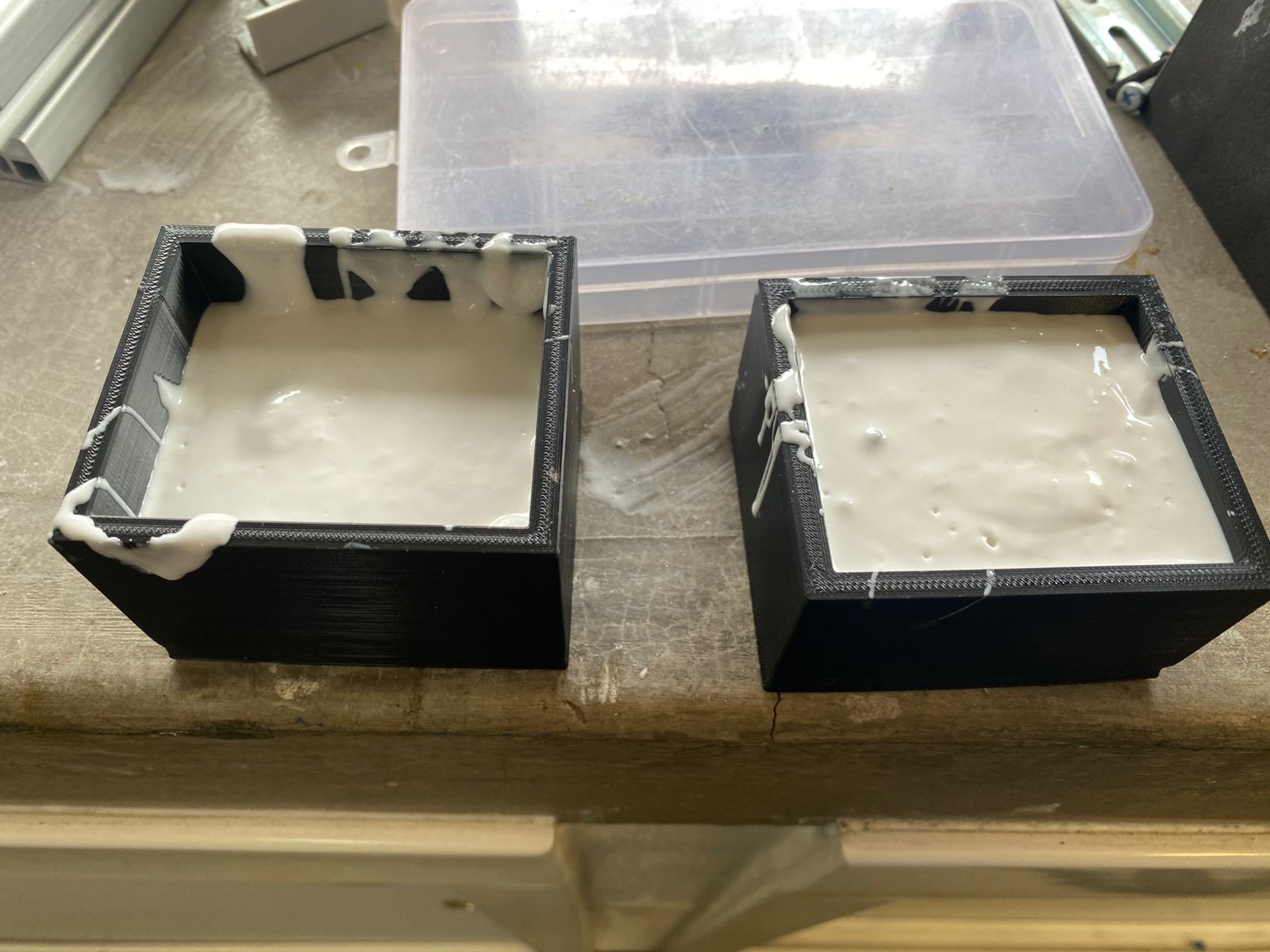
 After pouring, the silicone must cure for approximately 8 to 16 hours until fully solidified.
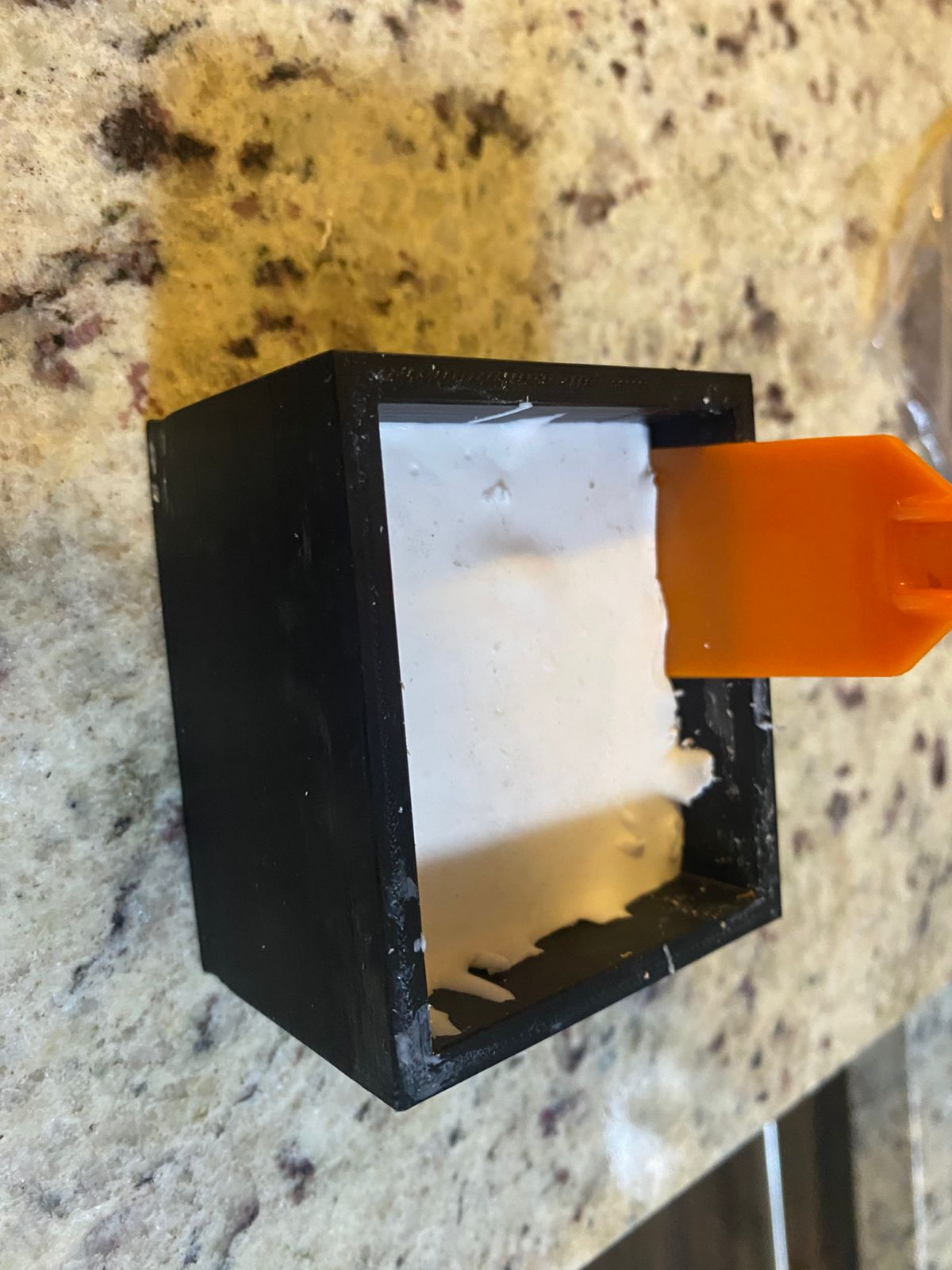
Demolding is relatively simple because the flexible silicone mold can easily be separated from the rigid counter-mold by applying a small amount of force.
 For the final piece, a candle is melted using a double-boiler method. The two silicone mold halves are then aligned face-to-face and sealed carefully to prevent leakage.
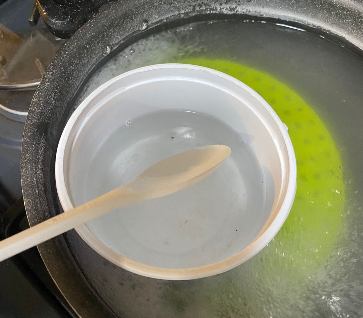
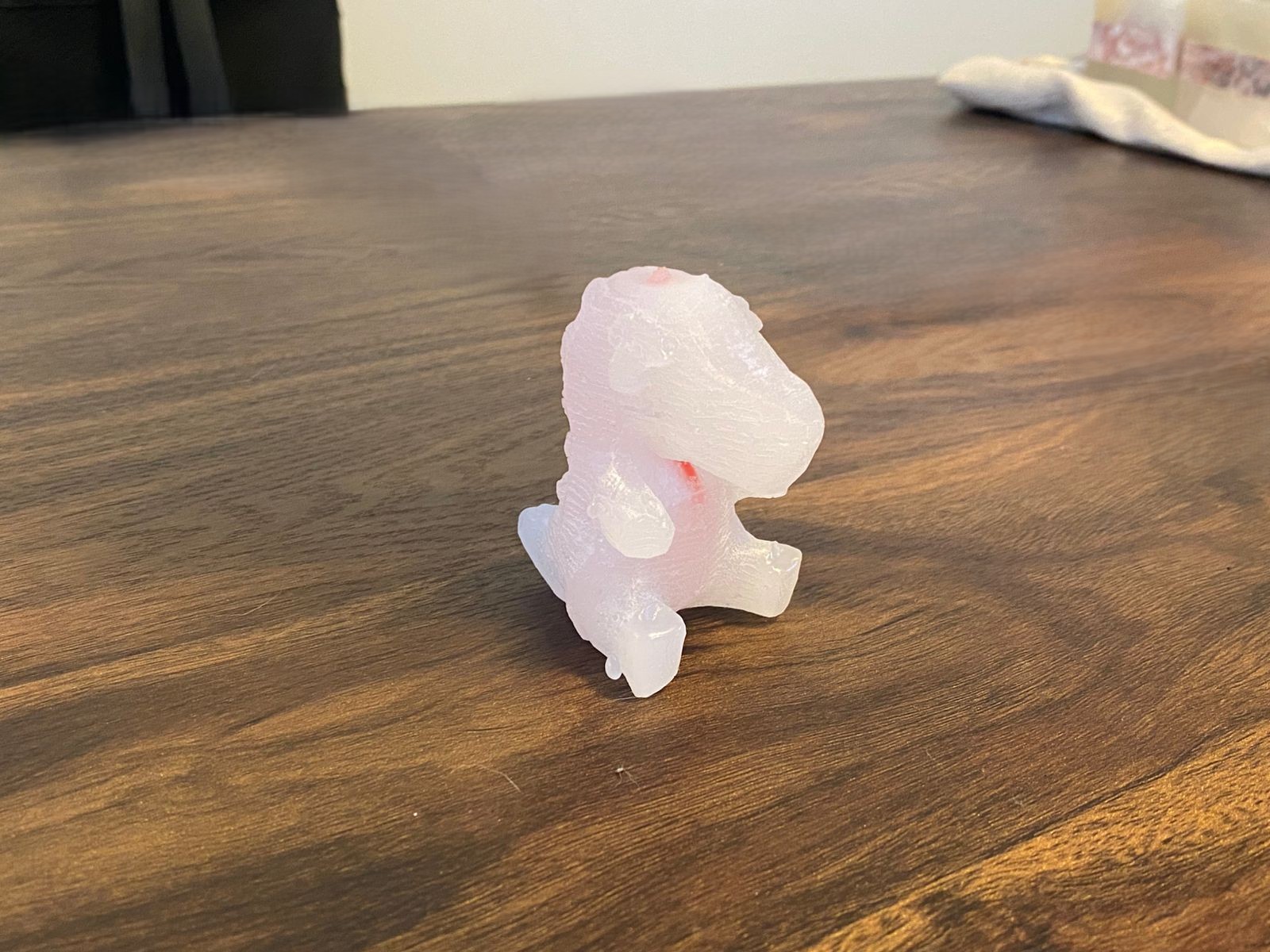
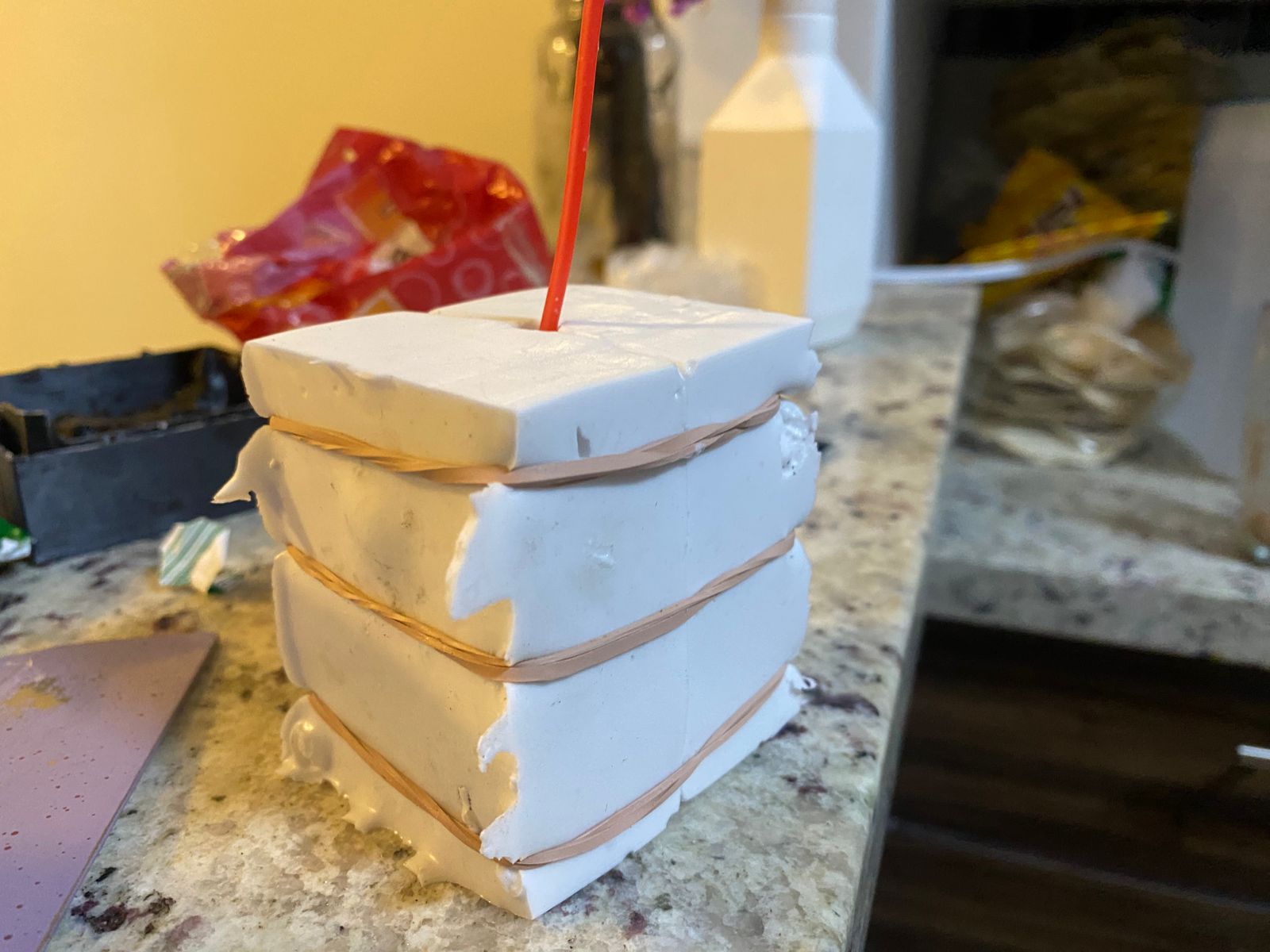 Once prepared, the melted wax is poured into the mold cavity and left to cool and solidify until the final object is obtained.
Results
Download files
For download 3D and others files, just click on the dancing shrimp.