7. Computer Controlled Machining
For this week's assignment, I decided to make a piece of furniture for my cat so he can play on it. The material they gave me at the FabLab was a 12mm*1.22m*2.44m plywood board with a 1/4 flat cutter.
It is important that to use the router you have the following safety equipment:
- Steel-toe boots
- Lab coat
- Safety glasses
In FabLab Puebla, we have two machines: the Asiarobot and the March 2/3. To find out more information about the parameters of these machines, you can visit the GROUP PAGE.
SOLIDWORKS DESIGN
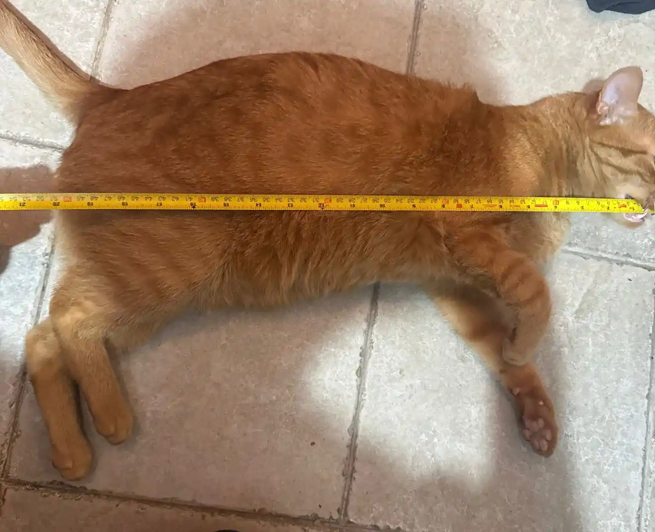
Since the furniture is for my cat, I designed the pieces considering its size, which is almost 51 cm long.
The pieces I created were the following; the important thing was that I designed the joining parts of my pieces with a 12 mm separation since my material is 12mm. This was thanks to what I learned on the group page where I saw that I needed a tolerance of 0.
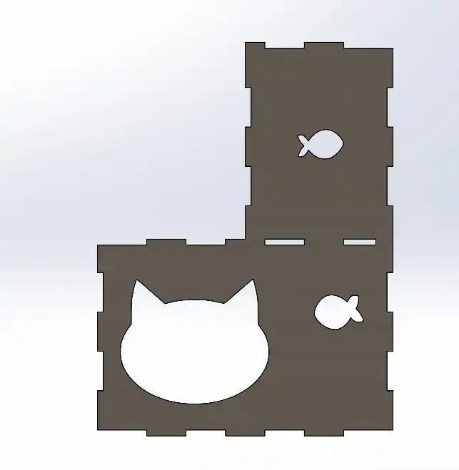
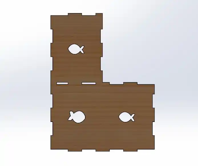
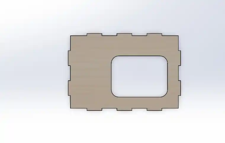
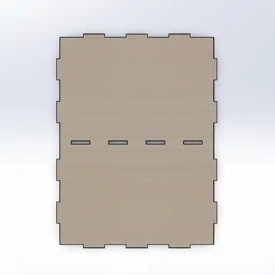
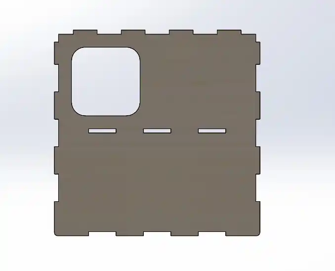
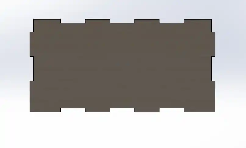
The first thing I did was make each of my pieces in SolidWorks and then join them in an assembly file to check that my design was turning out well.
To make an assembly in SolidWorks you must do the following:
- Open an assembly file in SolidWorks.
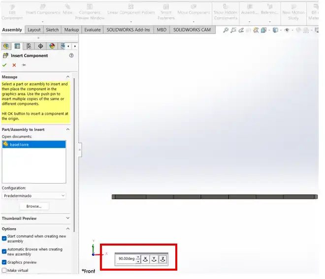
- Insert the parts in the SolidWorks menu under insert a component.
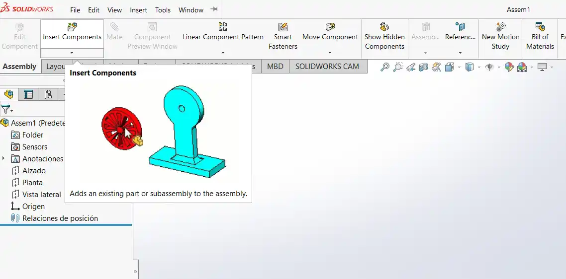
- Once you import the components, in the following menu you can change the rotation of the part.
- Then we insert the other component and we can start placing the mates in our assembly.
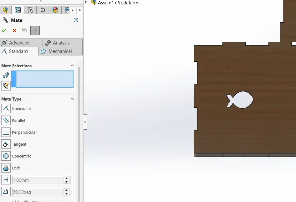
- You select the type of mate you want; you can use the following Mates:
- Coincident: Glues or joins two faces, points, or lines in the same space.
- Parallel: Keeps two elements pointing in the same direction, without ever crossing.
- Perpendicular: Fixes an exact 90-degree angle between two faces or lines.
- Tangent: Makes a curve or cylinder touch another surface at a single point, without passing through it.
- Concentric: Aligns the exact centers of circles or cylinders.
- Lock: Completely freezes two parts; if you move one, the other follows.
- Distance: Fixes an exact separation between two elements.
- Angle: Fixes an exact tilt in degrees between two faces or lines.
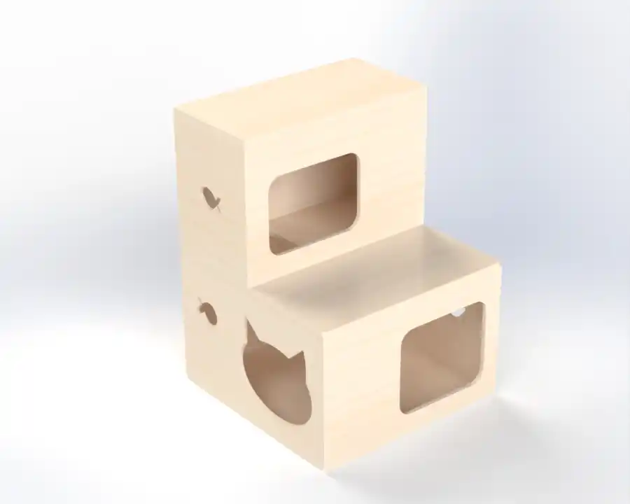
- This is how the assembly of my furniture ended.
To save my file, I placed all my pieces in a SolidWorks drawing with the size of my material and started placing my pieces. This is how my drawing turned out; it is important to check that the drawing is at a 1:1 scale.
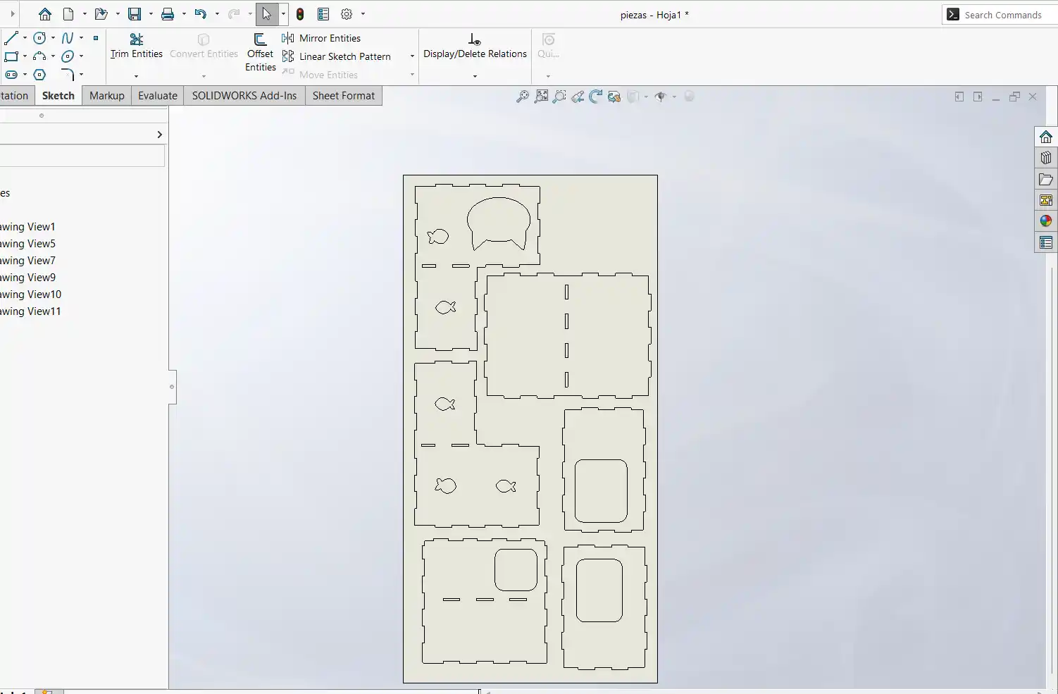
Then I saved my file as DXF.
VCARVE
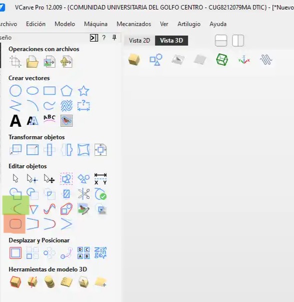
- The first thing I did was create a new file.
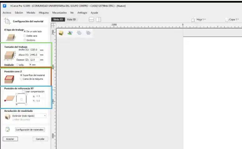
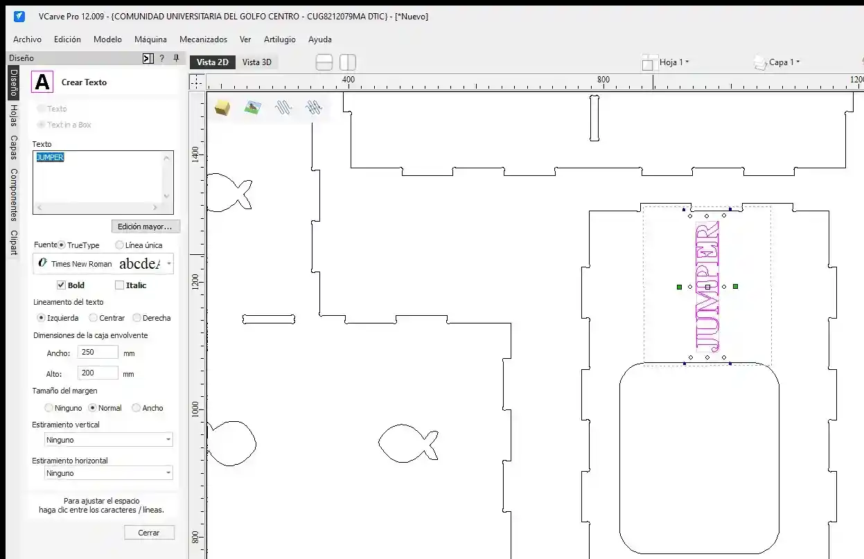
- Then I placed the measurements of my board in the green outline. In the orange menu, I placed where I wanted the Z position, which in my case I set to the material surface, and in the blue menu where I wanted the XY reference point, which in my case was on the bottom left side.
- In the file menu under Import > Import bitmap, we added our DXF file.
- Now that we have our pieces, we need to join the vectors, so we use the orange option.
- Once they are joined, we have to add a "femur head" (dog-bone) fillet with a radius of half the diameter of our tool, which in my case is 3.175 mm but to add tolerance I used 3.4 mm as recommended by my instructor. To do this, select the green option.
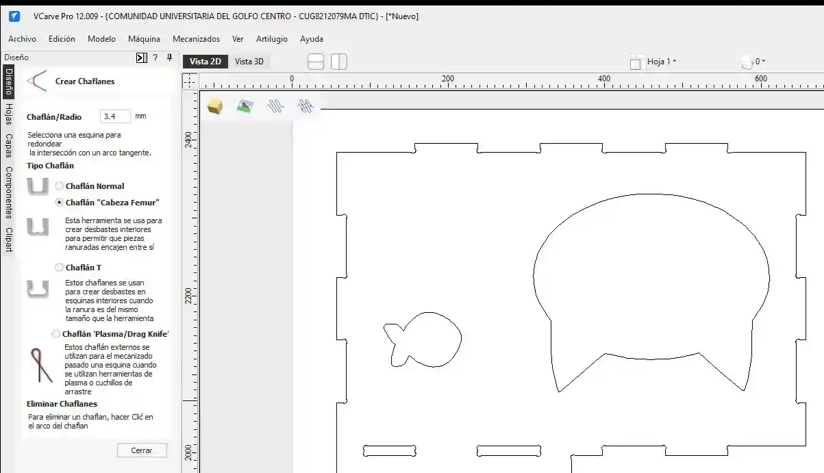
This helps us create internal pockets to allow the pieces to fit together.
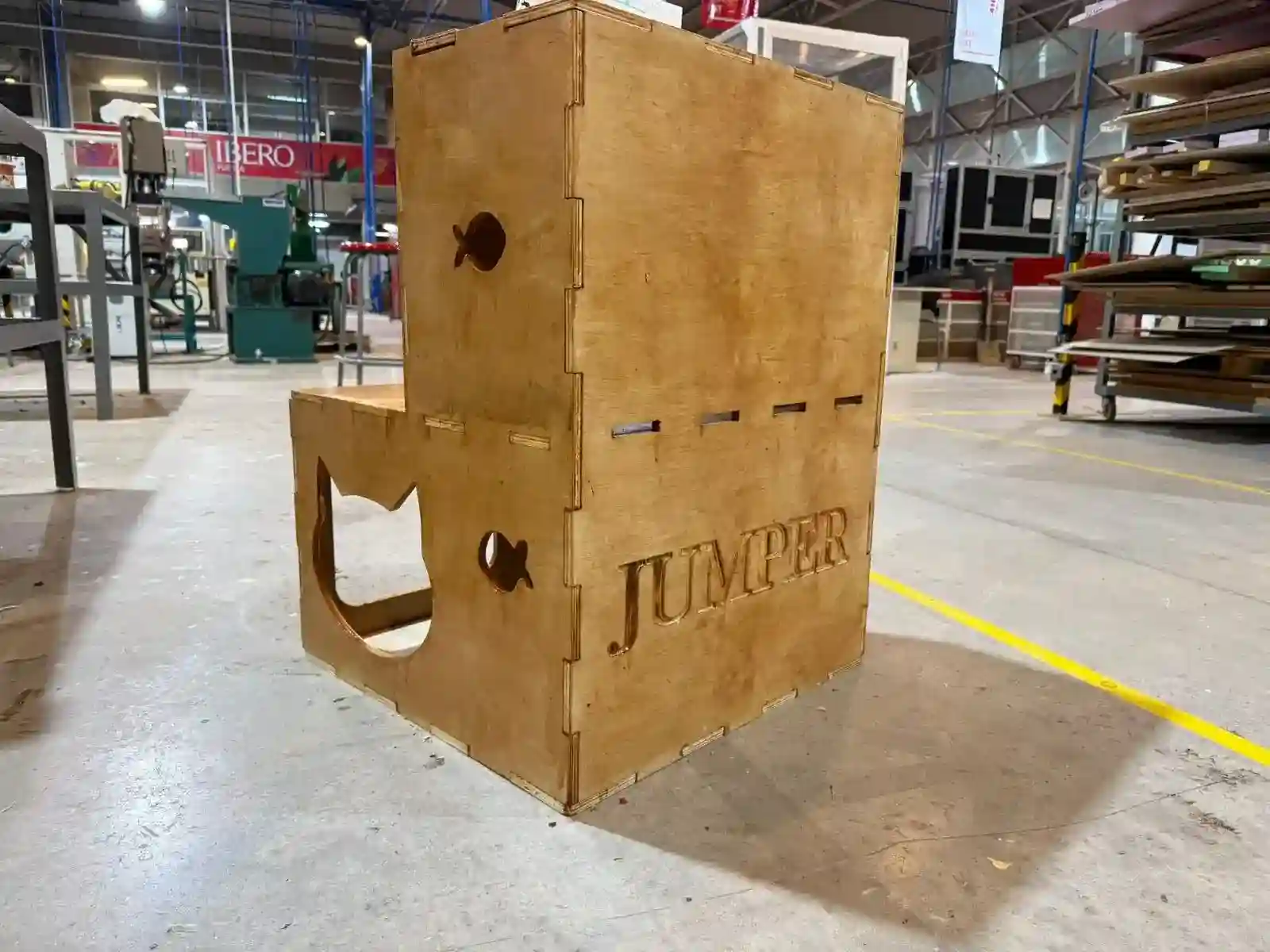
- I wanted to add my cat's name to do the engraving, so in the text tool, I added it and changed the size, font, and position.
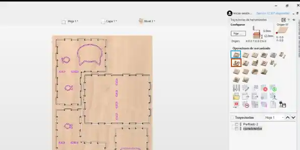
- I started selecting the type of toolpath. In my case, the first thing I did was add the engraving in the orange option and then the blue option for the cuts, which is 2D Profile.
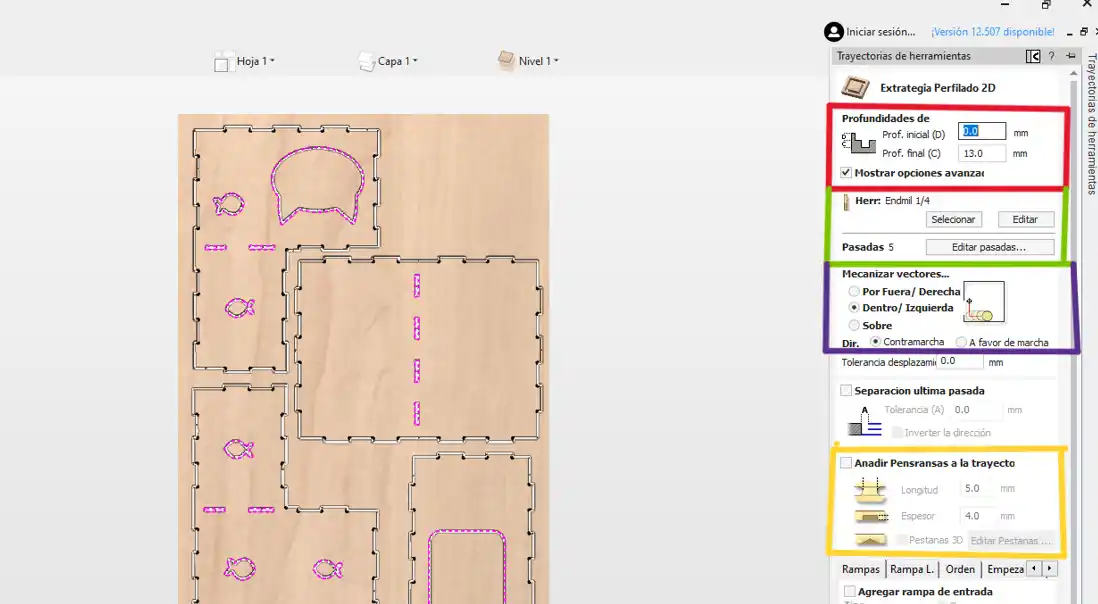
Within the 2D profile option, you can change the following options:
- Orange: We change the depth to where we will make the cut, the thickness of our material plus 0.5 or 1 mm more to make sure it cuts.
- Green: Menu to change our tool with the select option.
- Purple: Select the type of machining; the outside option is for external cuts, and the inside option is for cuts that will be holes.
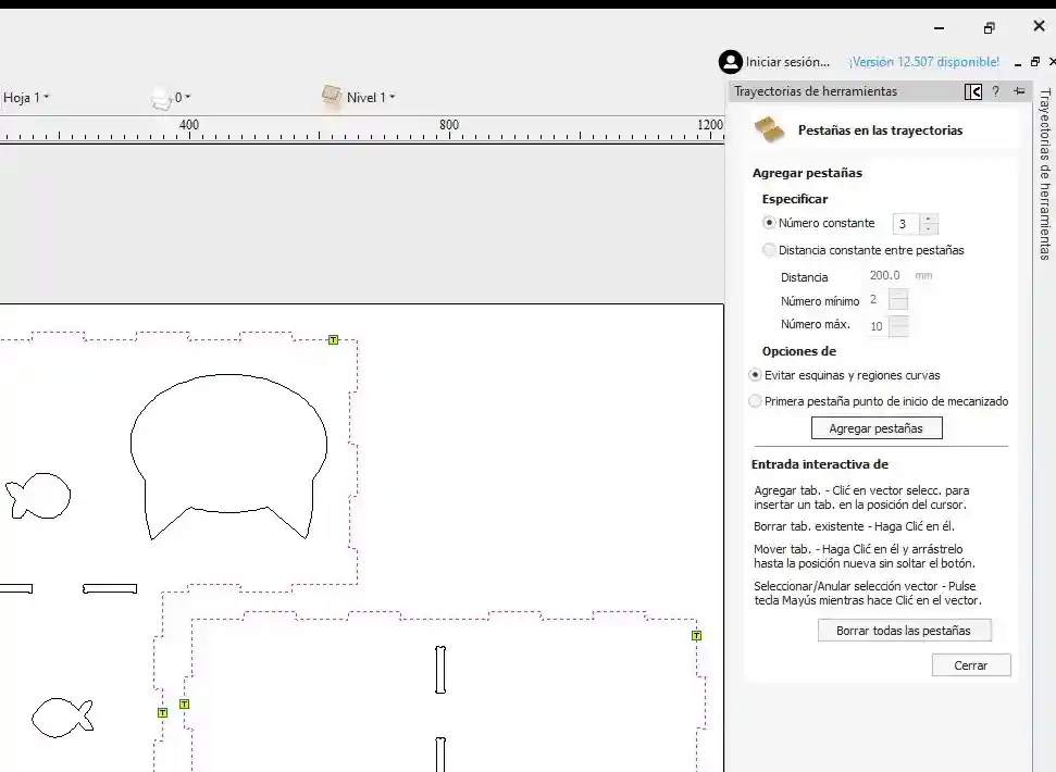
- Yellow: Add tabs. We must activate this option so that the pieces don't fly off when making the cuts; in my case, I placed tabs 5mm long and 4mm wide, considering that my speed is 4000 mm/min.
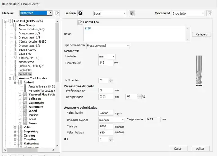
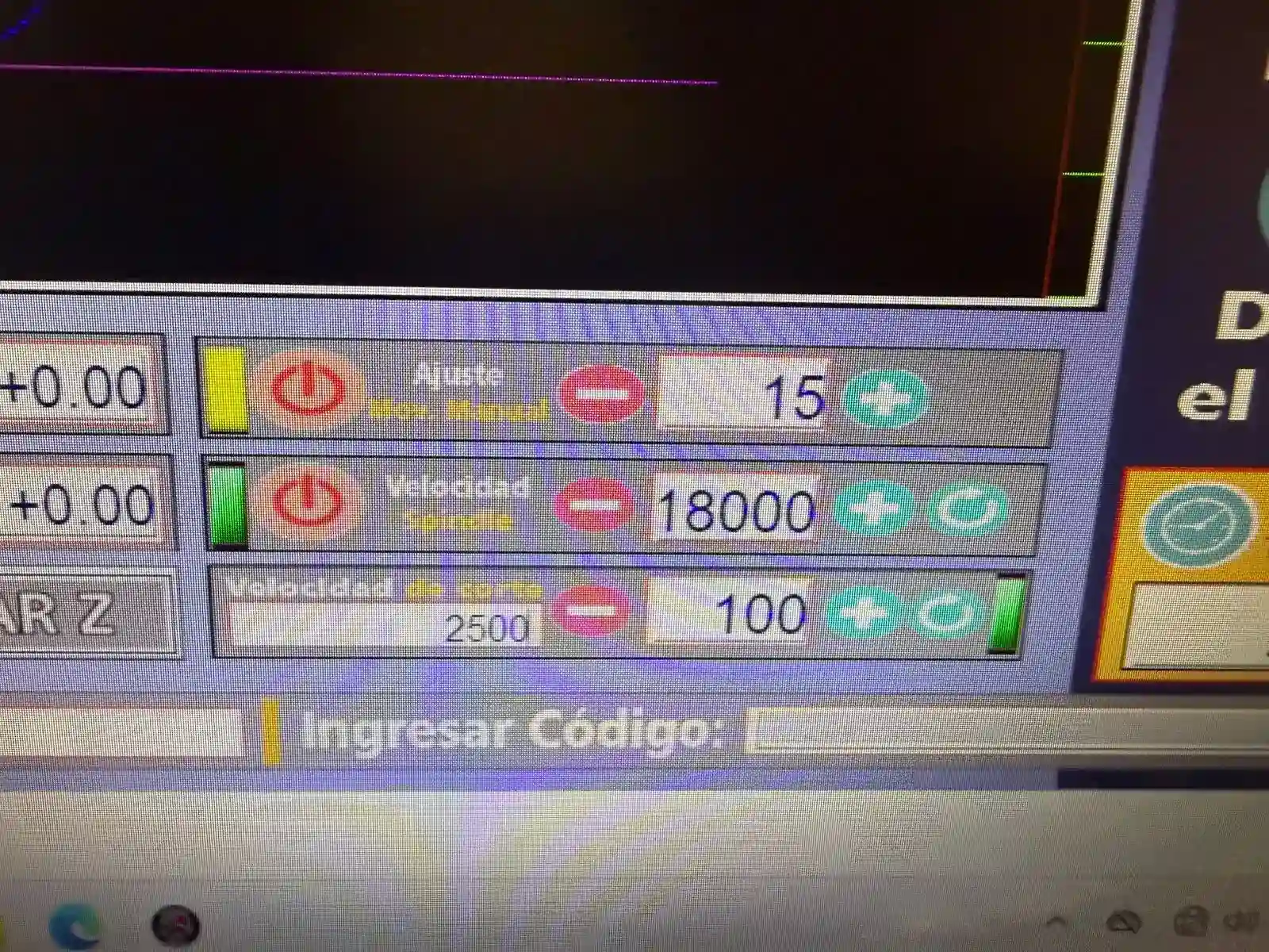
Tool: In the tool menu, we look for the one we are going to use and change the number of flutes the tool has, the revolutions per minute, and the plunge rate. In my case, it says 9000 in the image, but I actually used 4500; you can get this with the help of the following calculator.
Additionally, when running the program on the router, it sometimes reduced the speed to 50%.
Tabs: I placed 3 tabs on each of my pieces and clicked to add tabs. If you see that they were placed in inconvenient spaces, you can change the location of the tabs and click close.
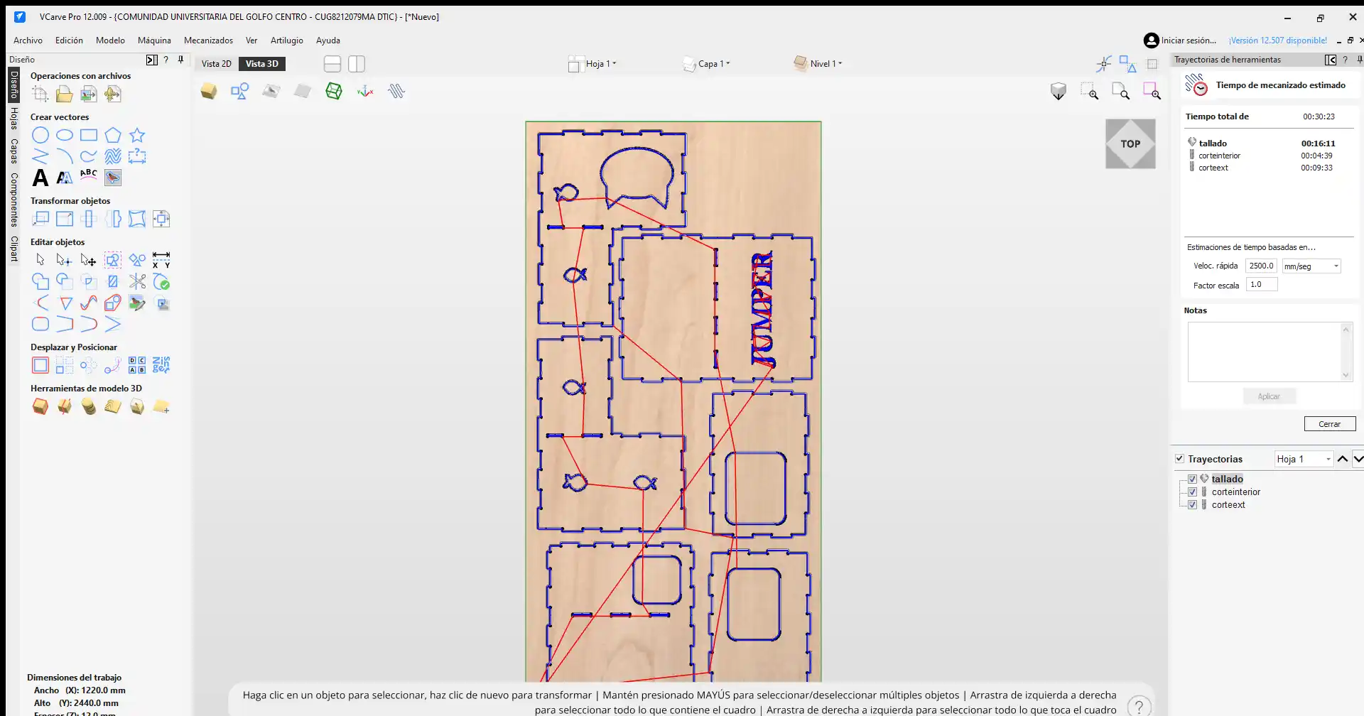
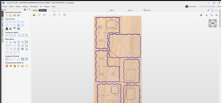
- To calculate the toolpath, I clicked on calculate, and then I had my 3 files ready: the outer cut, inner cut, and engraving.
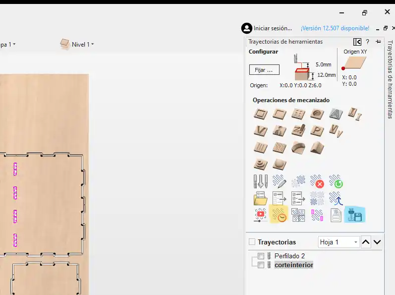
With the yellow option, we can see how much time our file will take, and the blue option is used to export the file to our USB.
In the export option, we must set the machine we are going to use.
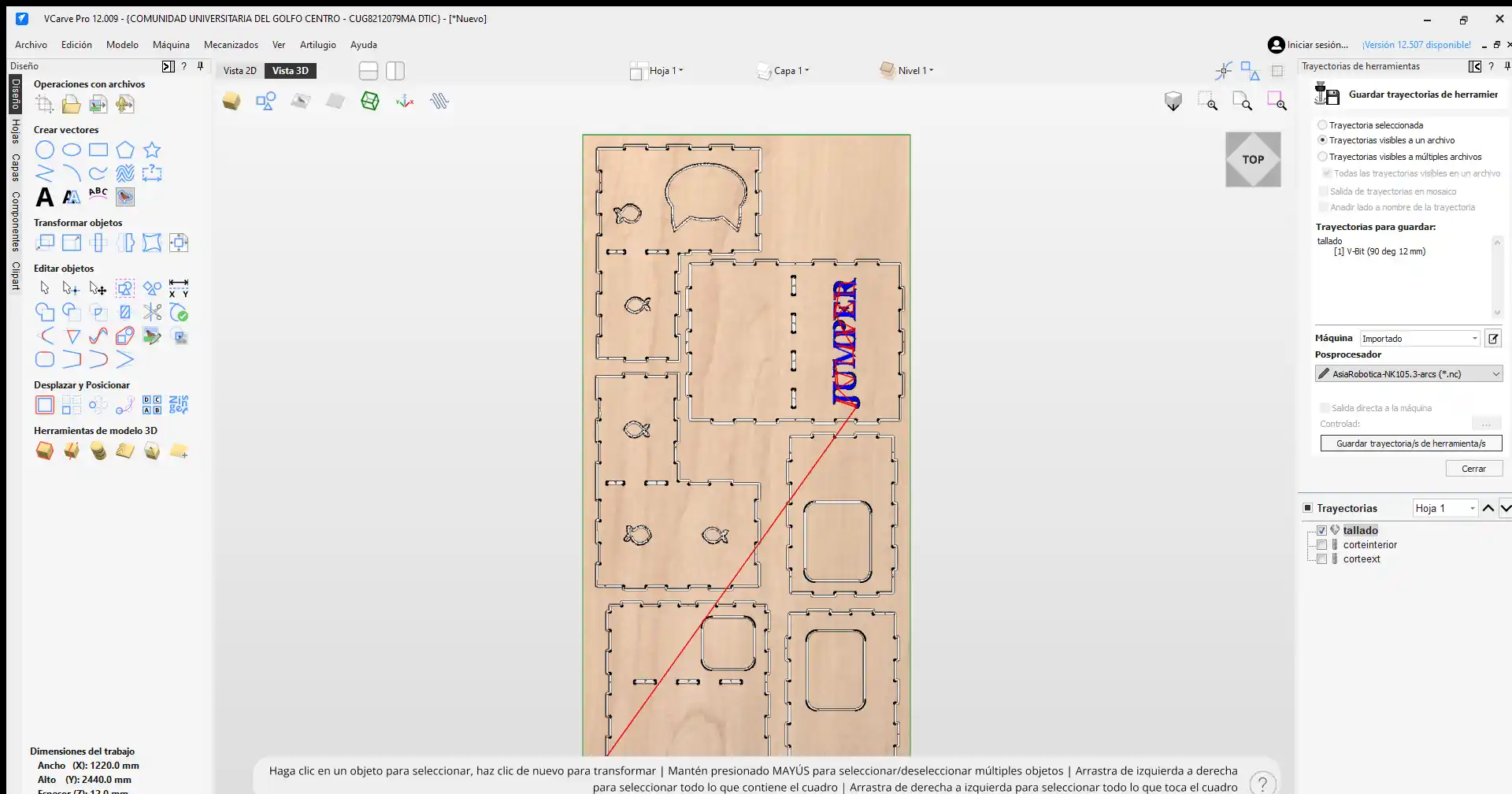
This is what the simulation of my files looks like.
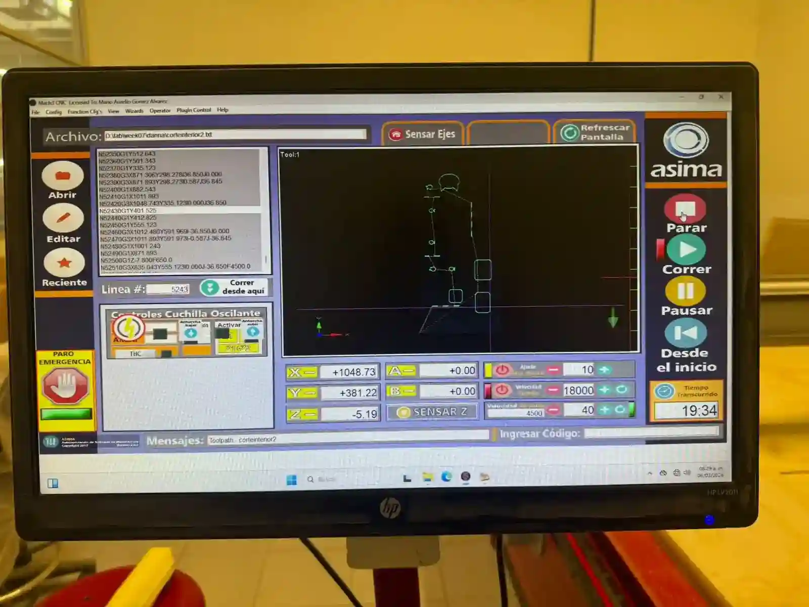
Machining
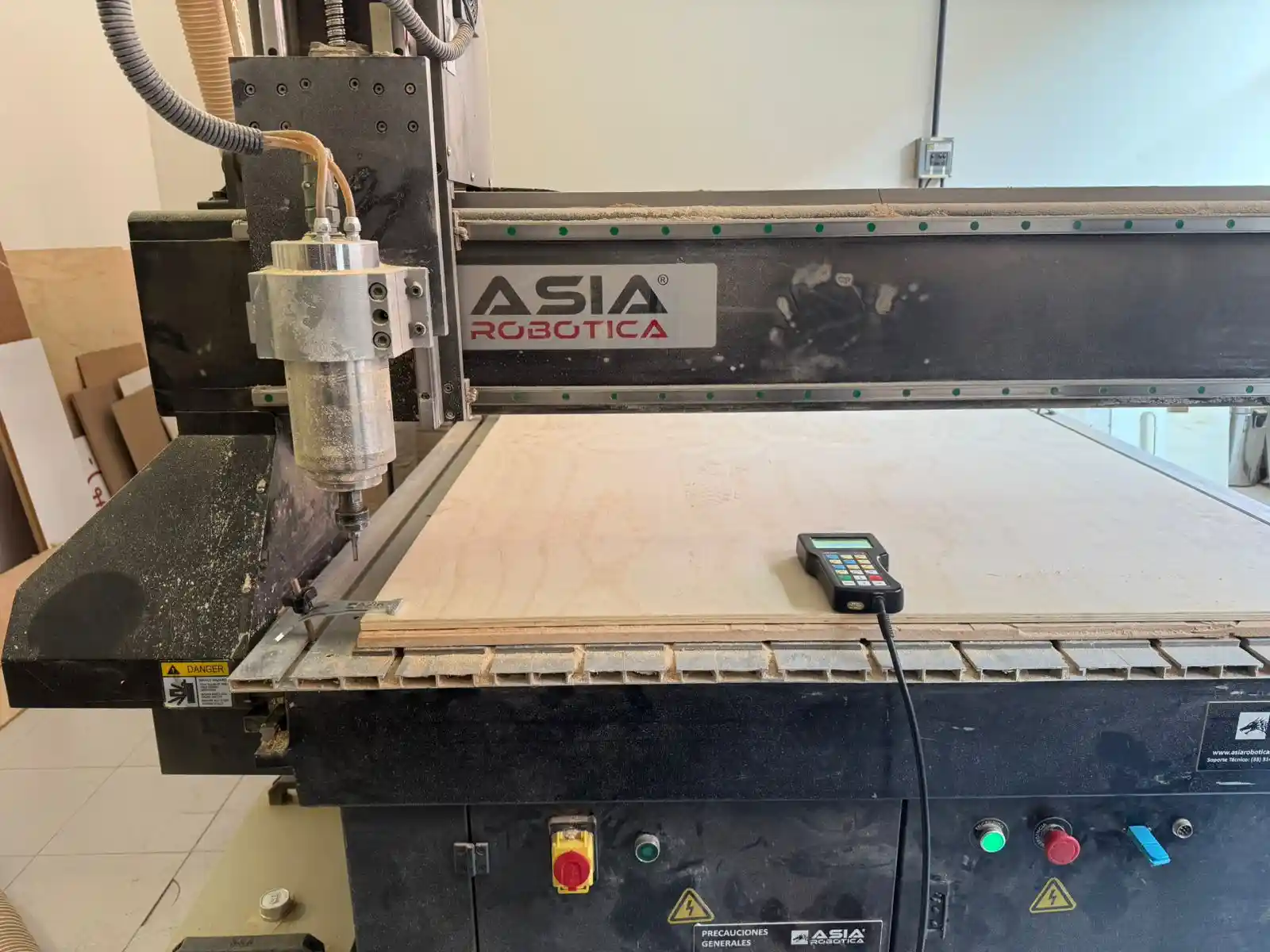
ASIA Robotica
This is how the ASIA robotic machine works.
- Save the file in NC format.
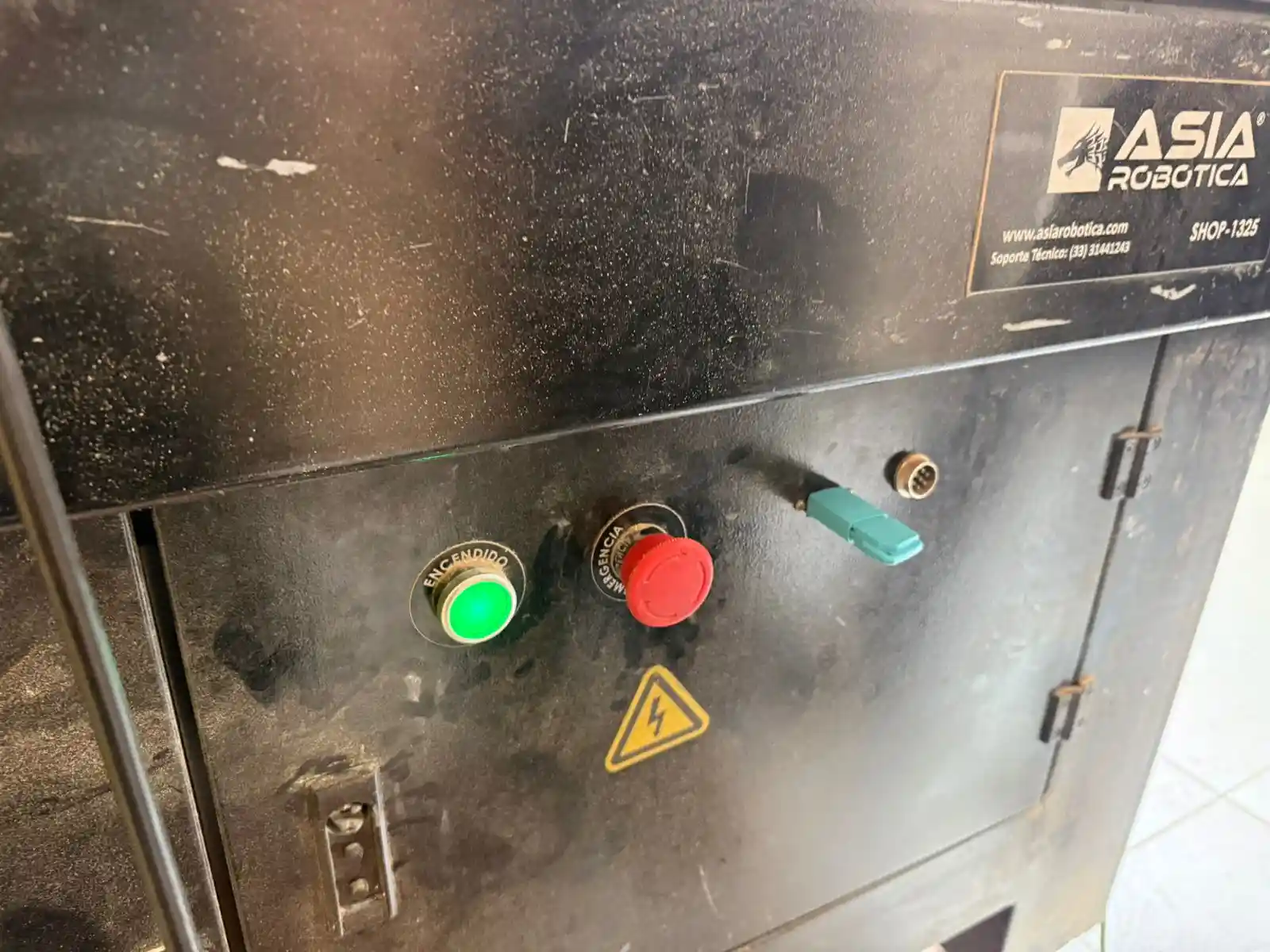
- The first thing we must do is release the emergency stop and press the green button.
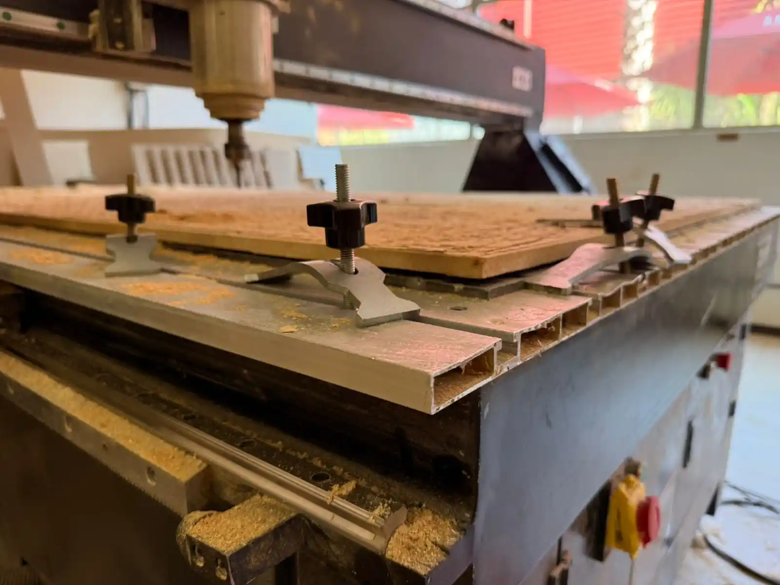
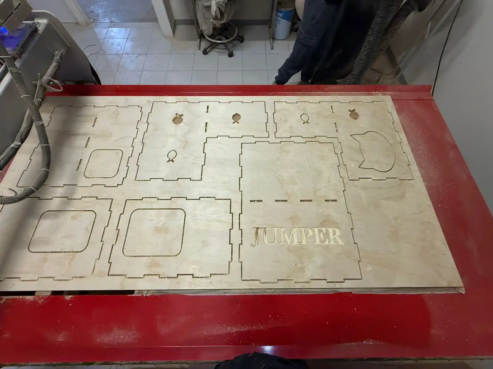
- To place the material on the machine bed, we have to use the clamps symmetrically around the sheet, but we can also adjust their position to reduce buckling in certain sections along the edges.
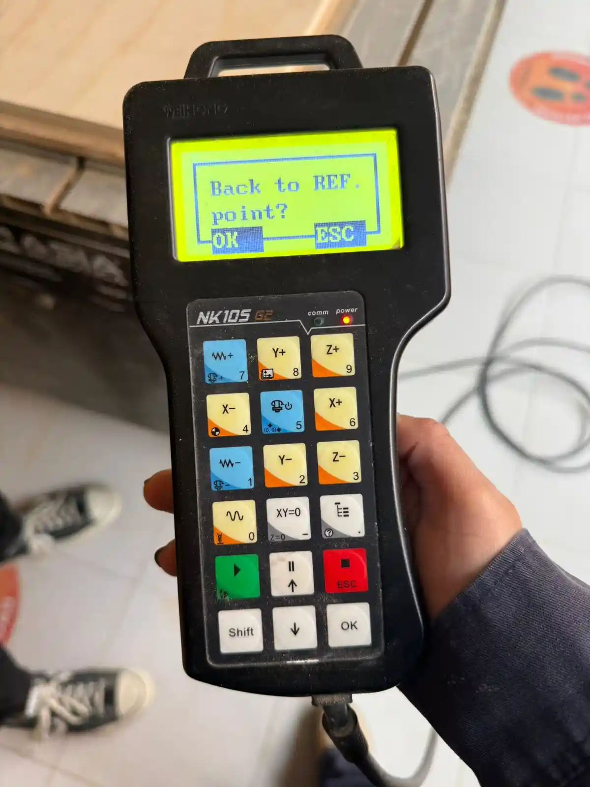
- The first thing that comes up when turning on the machine is if you want the machine to return to the reference point; we must click OK.
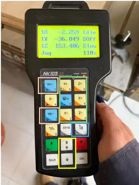
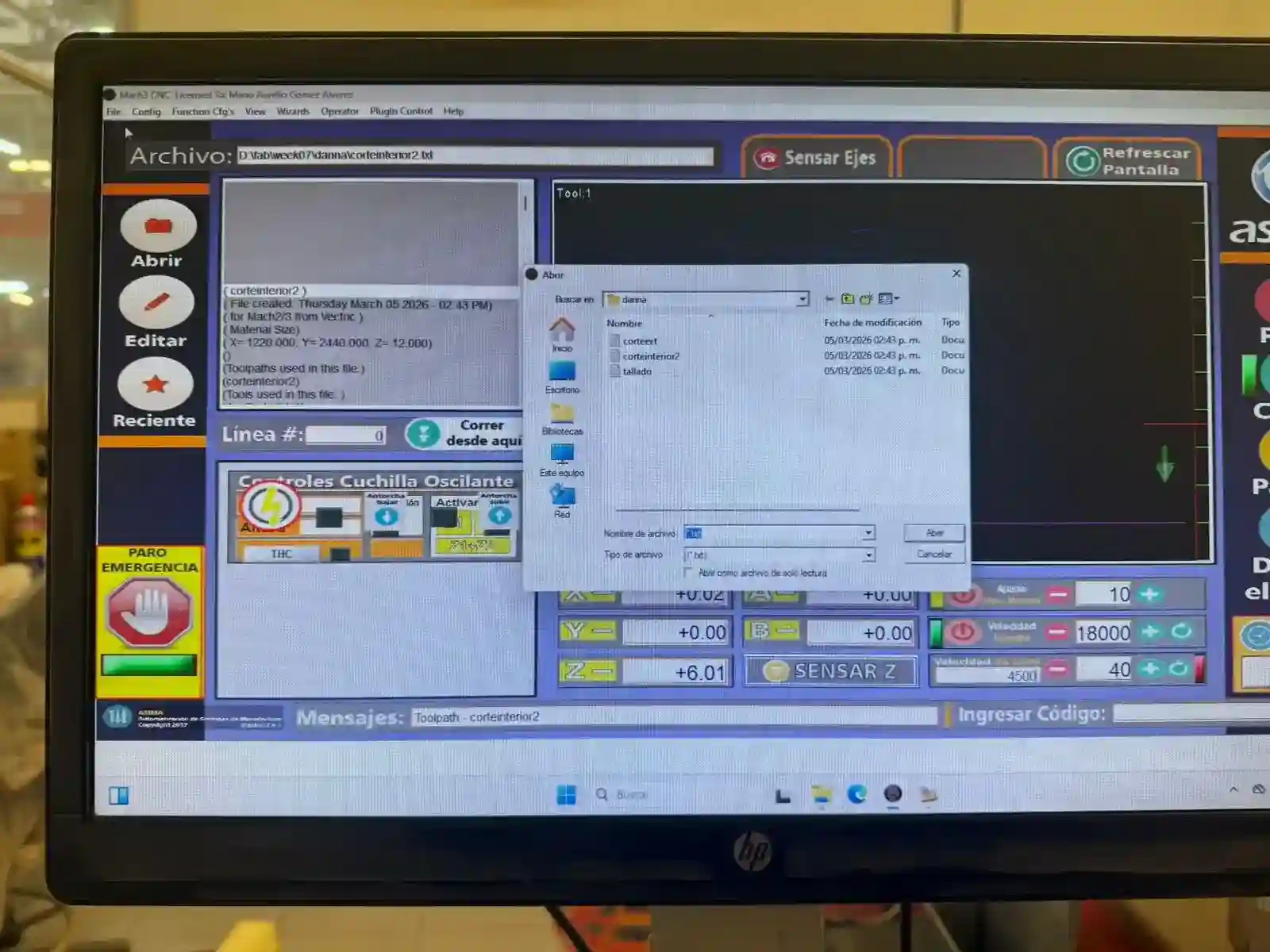
- The orange squares are used to lower the movement speed, the green ones for the axis we want to move, the blue one is where we can find the files, and the yellow ones to move between the files.
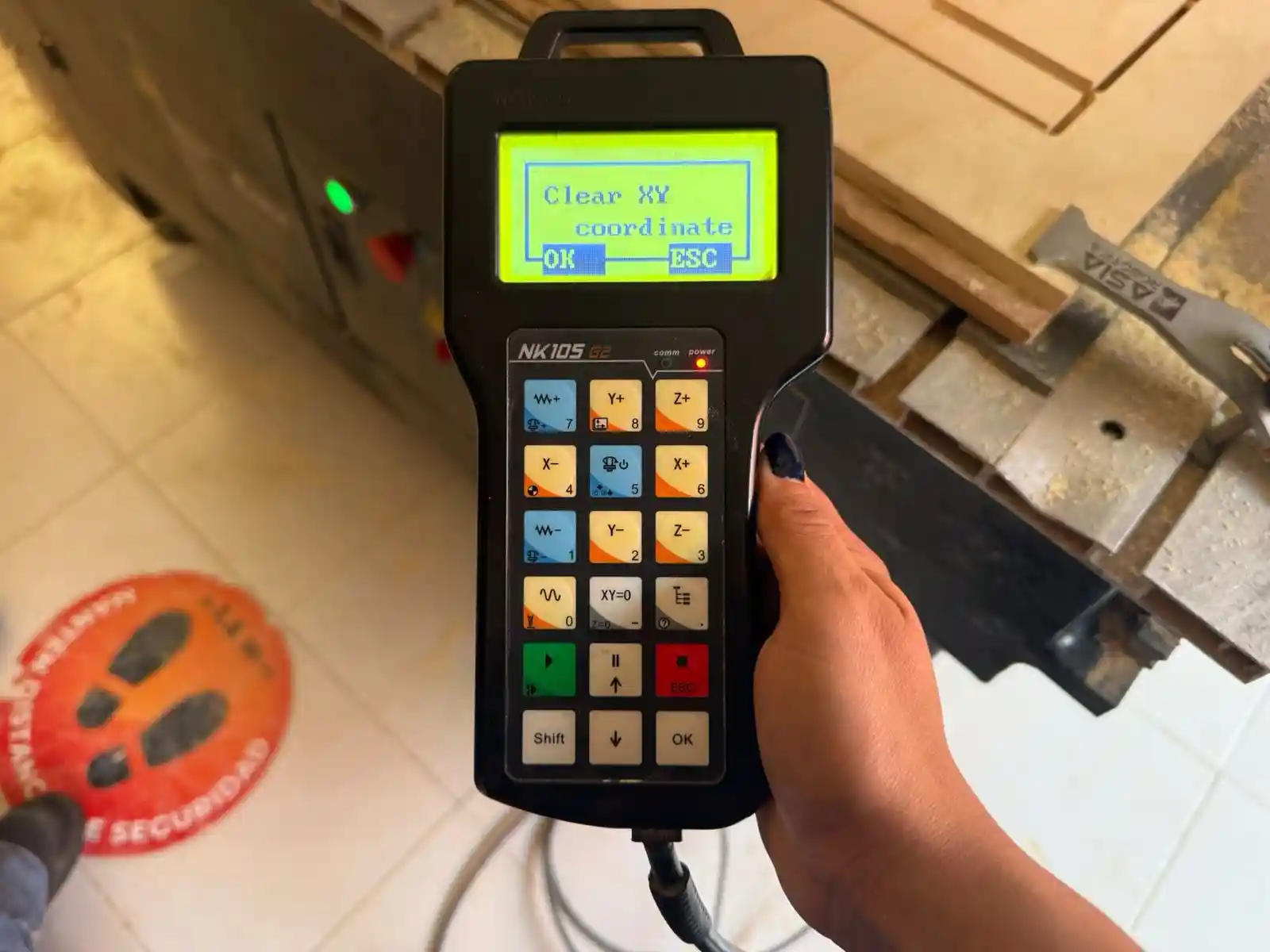
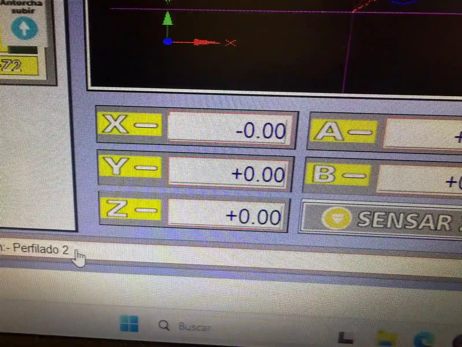
To mark the reference point, we must press the XY=0 button for the XY axis, and for the Z axis, we press Shift and XY=0.
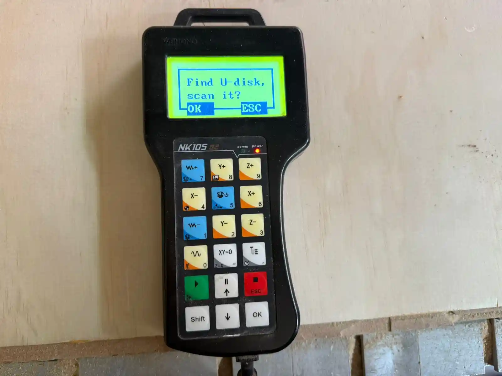
- To read the memory in files, we click scan U-disk > OK.
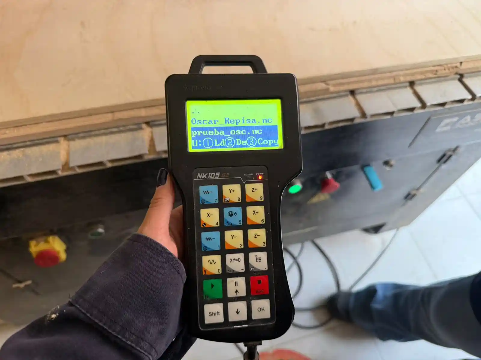
- We select the file with OK and then button 3 to copy it to the machine.
- We select the file and click the green PLAY button.
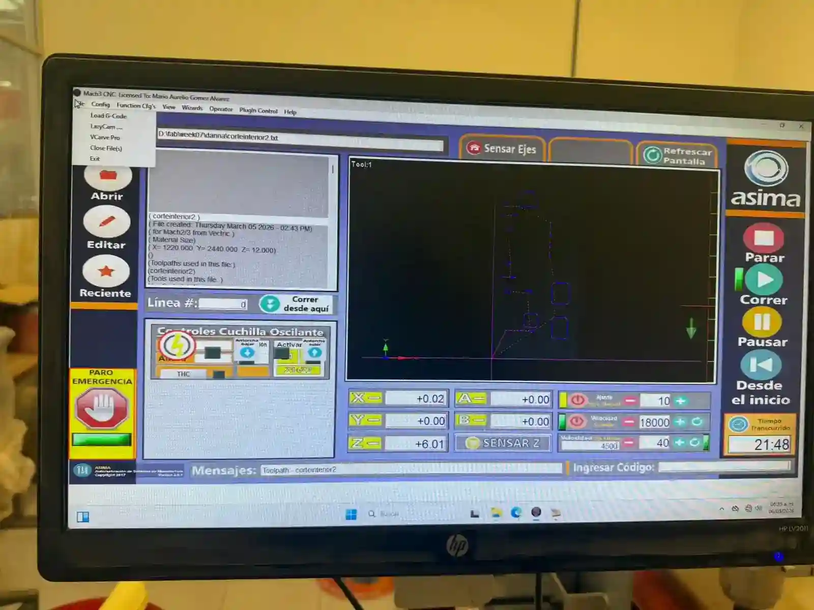
First I placed my engraving file, then the internal cuts one, and finally the external cuts one.
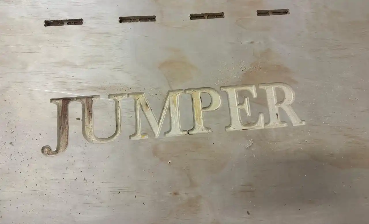
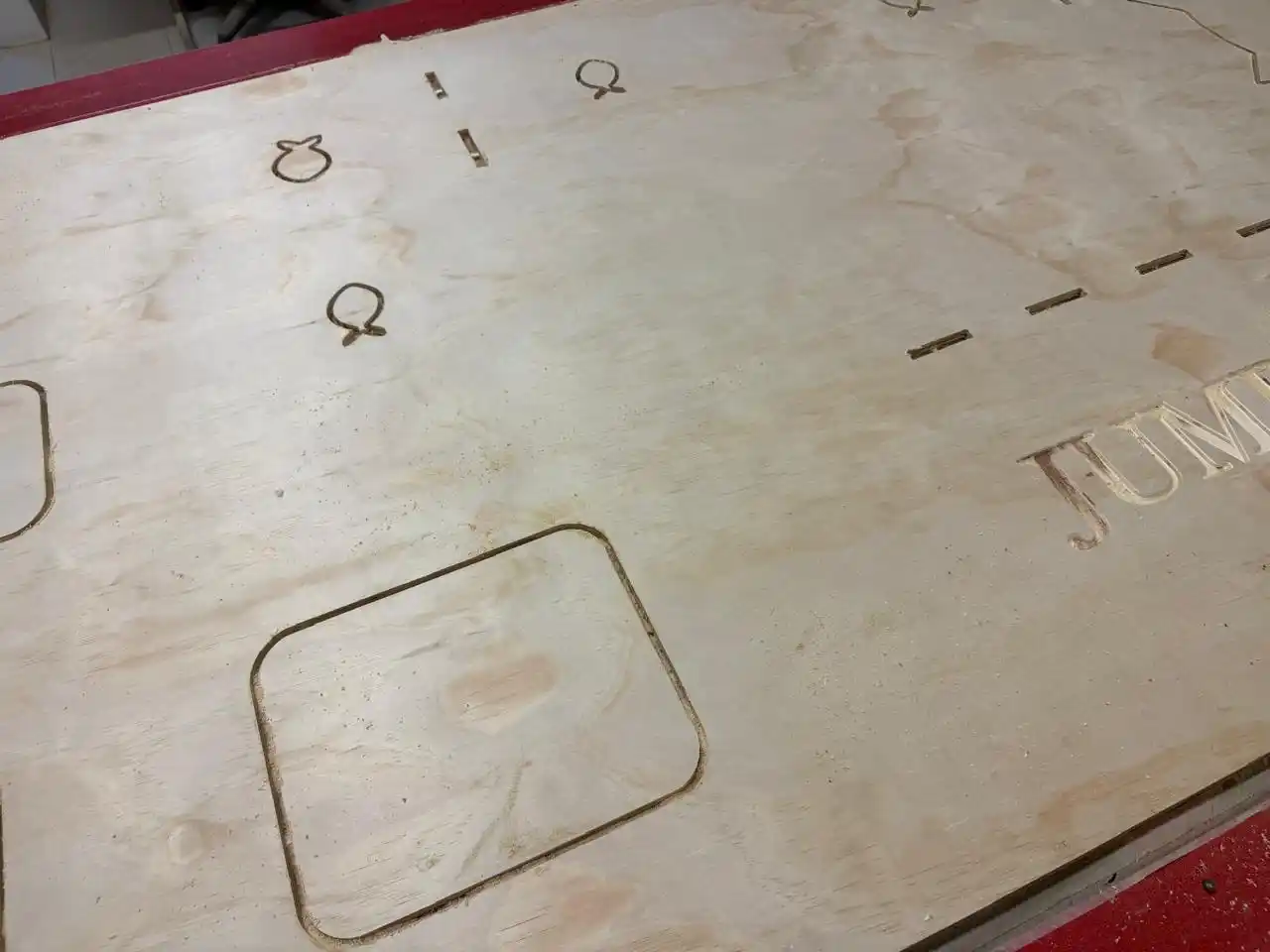
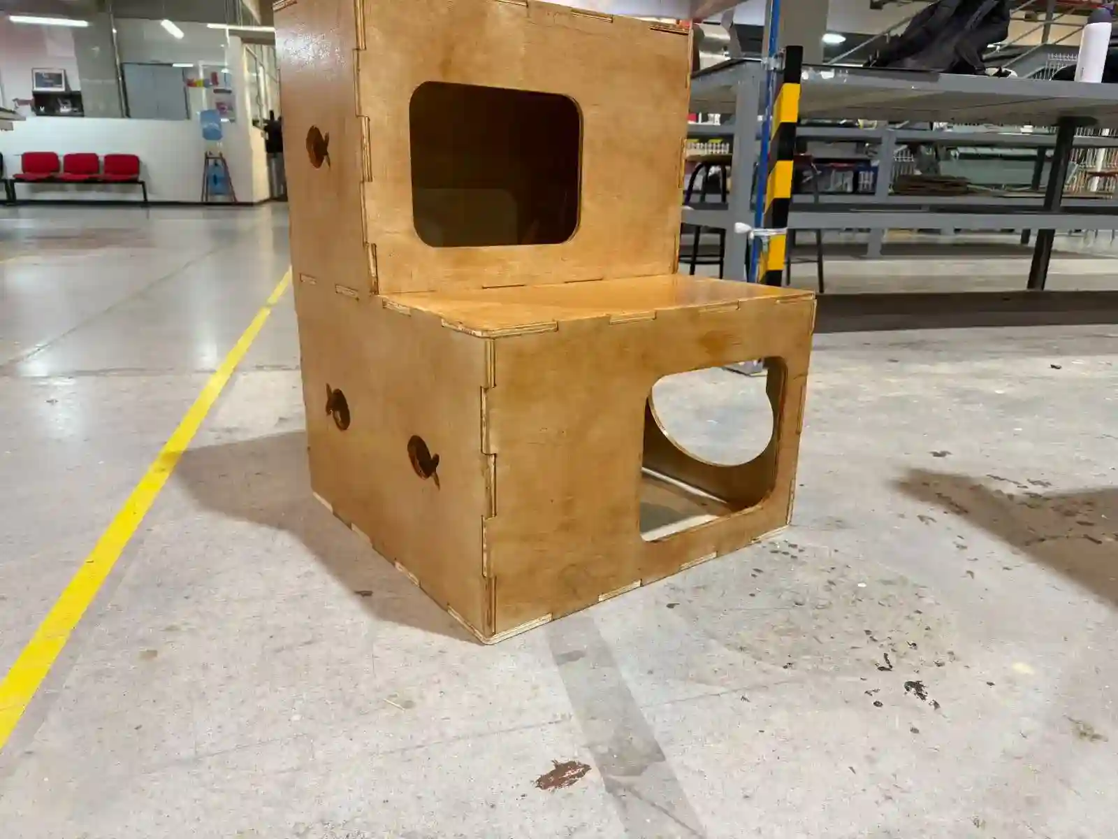
This is how my pieces came out.
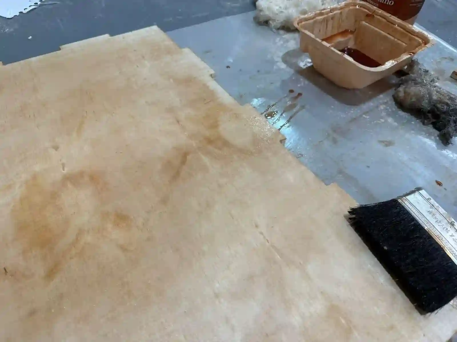
Then I wanted to add a varnish to give it color.
This is how I assembled my furniture; thanks to my boyfriend for giving me a hand. If you want to see his FAB page.
Final Result
Learnings
During the assembly process of the cat house, I encountered some complications with the joint tolerances and had to use a rubber mallet to fit the pieces together. I learned that plywood is highly susceptible to ambient humidity, which caused the material to expand. Additionally, applying varnish before assembling further reduced the clearances.
The most valuable lesson I take from this is the importance of parametric design. For future projects, I will set the material thickness as an adjustable parameter in my CAD model. This will allow me to measure the actual thickness of the treated material right before milling and quickly adjust the design to ensure a perfect press-fit.