5. 3D Scanning and Printing
This week's assignment focuses on exploring the world of additive manufacturing and 3D scanning technologies. Unlike subtractive processes (such as CNC milling), where material is removed from a solid block, 3D printing allows us to build objects layer by layer. This opens the door to complex geometries that were previously impossible to manufacture.
For more details on our printer characterization tests, including clearance scales and 3D scanning benchmarks, visit our GROUP PAGE.
1. What is 3D printing?
3D printing is an additive manufacturing technology. The process begins with designing a model using Computer-Aided Design (CAD) software. Once the design is complete, the file is converted into a compatible format and processed through a "slicer" program.
This software divides the model into horizontal layers and generates the instructions (G-code) for the printer to follow. Finally, the printer deposits the material layer by layer to form the physical object.
Common Types of 3D Printing:
- FDM (Fused Deposition Modeling): This method uses a plastic filament (such as PLA or ABS) that is melted through a heated nozzle and deposited onto a build platform.
- SLA (Stereolithography): This technique uses a photosensitive liquid resin that is cured (hardened) by a laser beam or UV light. It is ideal for high-detail parts and smooth surface finishes.
- SLS (Selective Laser Sintering): This process uses a high-power laser to sinter (fuse) powdered material—typically plastics or metals—into a solid structure.
2. My model
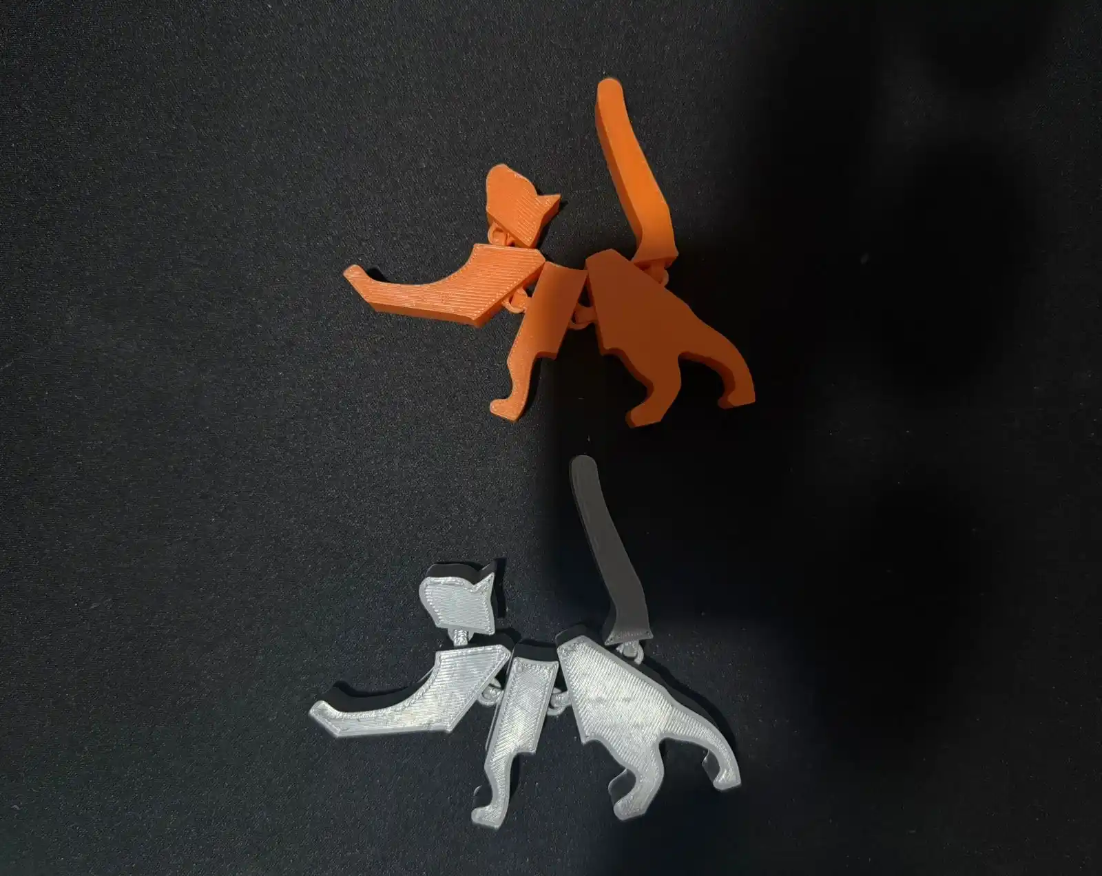
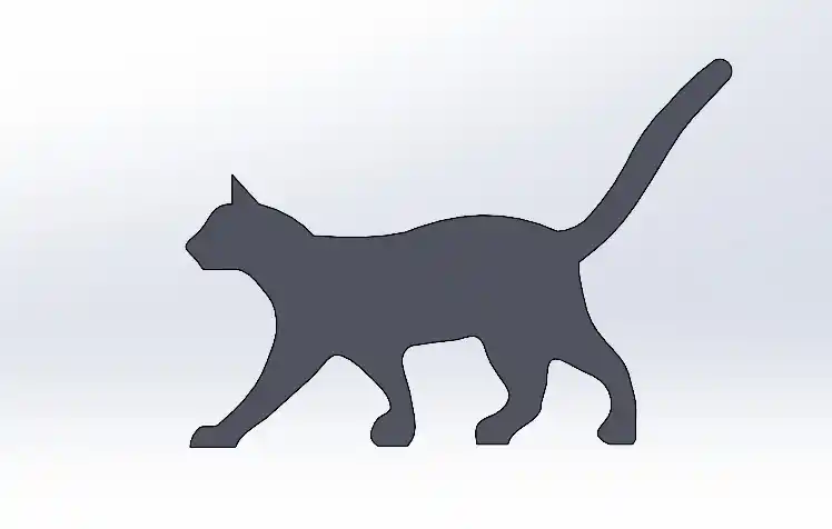
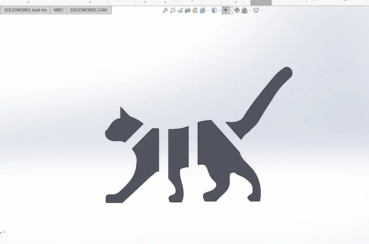
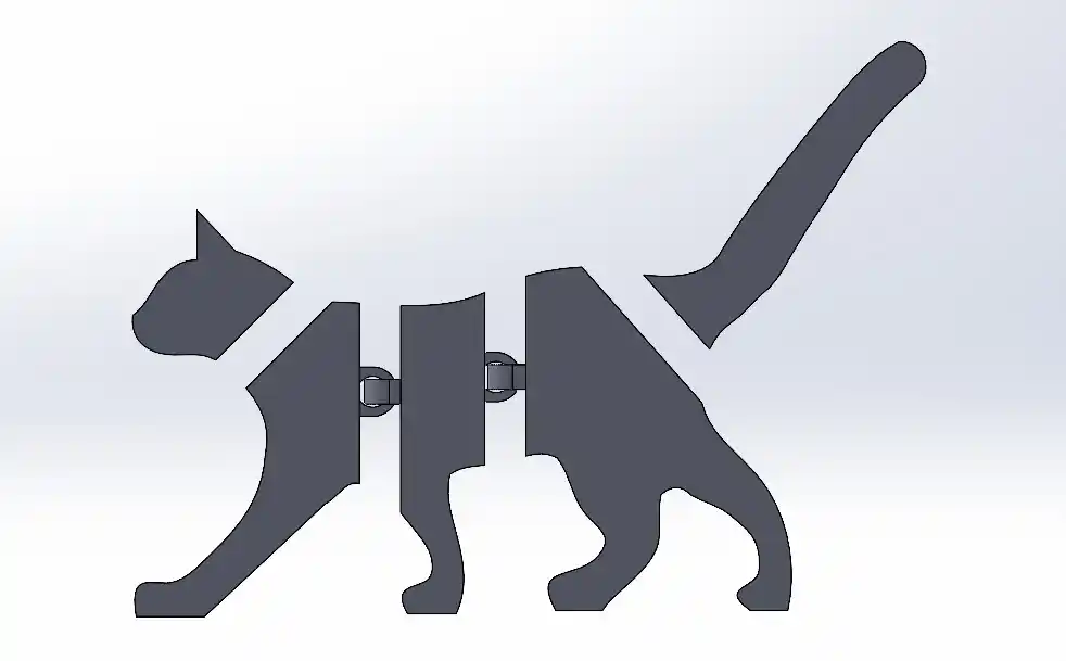
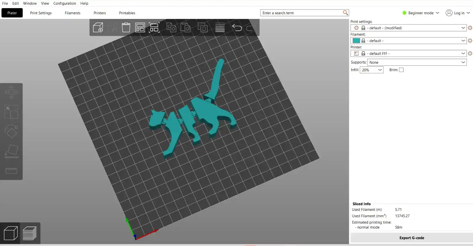
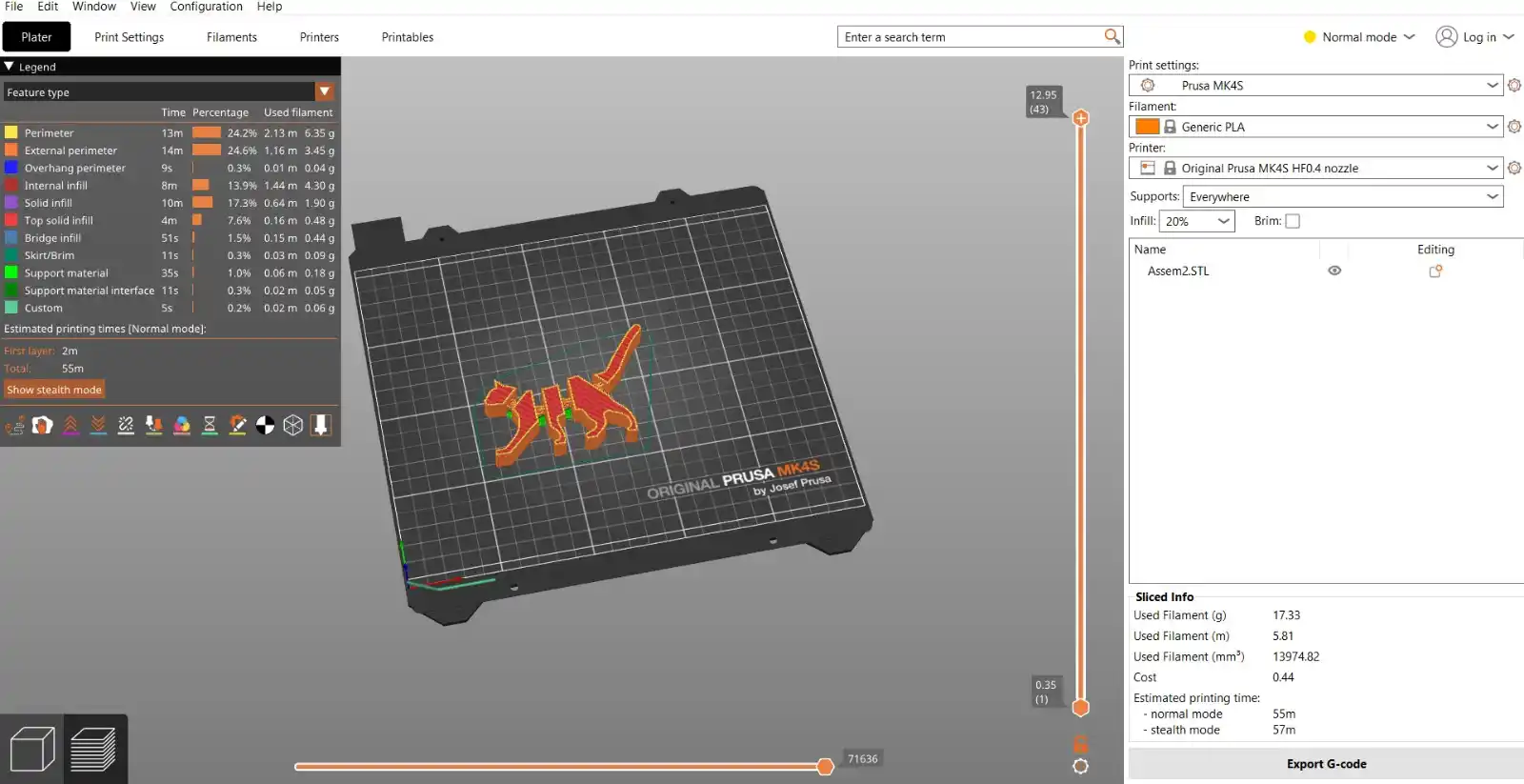
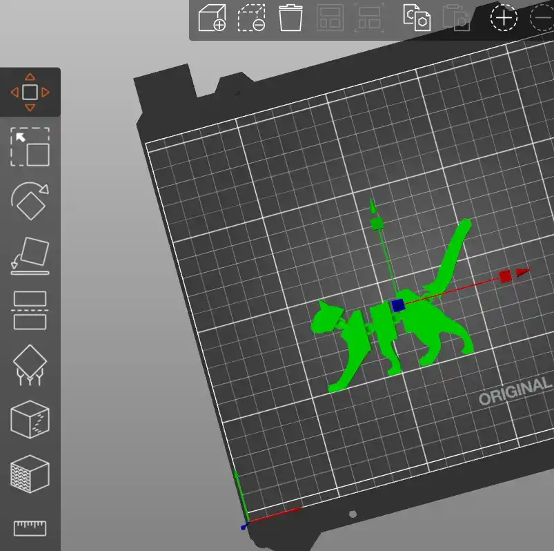
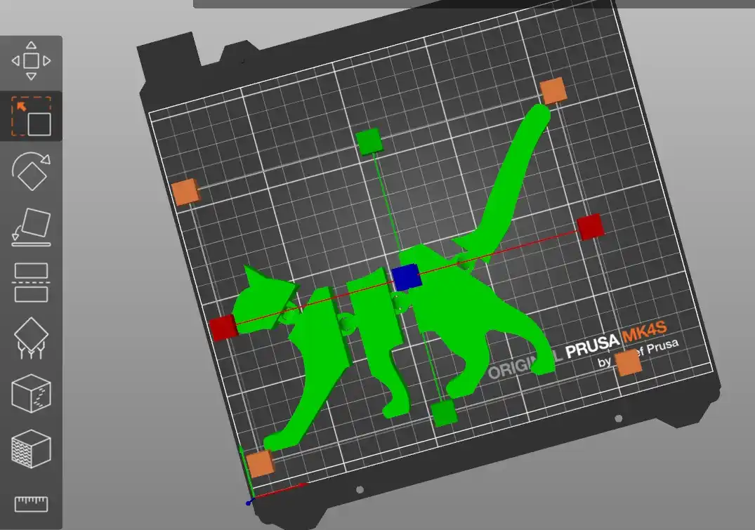
For this week, I decided to create a small cat-shaped toy with several joints to allow movement, inspired by a design I found on 3D TROOP profile on Cults3D.
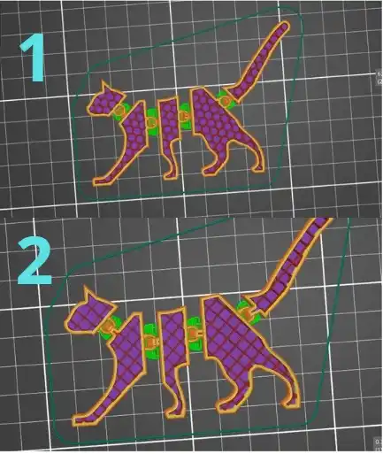
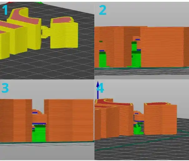
This part must be manufactured using an additive process because it features a Print-in-Place integrated assembly geometry with interlocking links, which are impossible to achieve through subtractive or formative methods. In a CNC milling machine, the cutting tools would lack access to the internal gaps to clear material without damaging the external structure. On the other hand, in injection molding processes, the part would remain trapped in the mold due to its captive joints, which do not allow for a viable parting line.
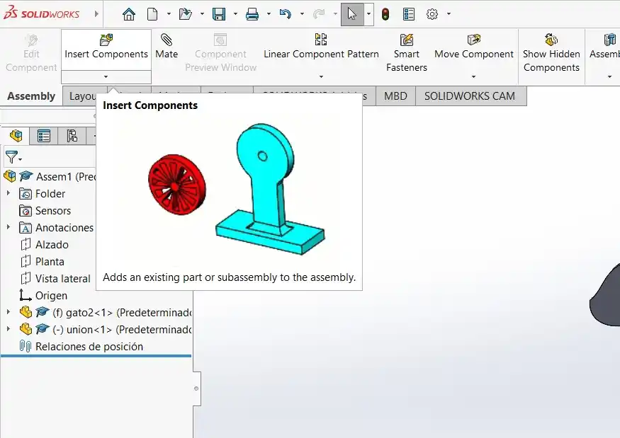
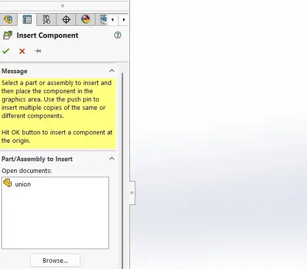
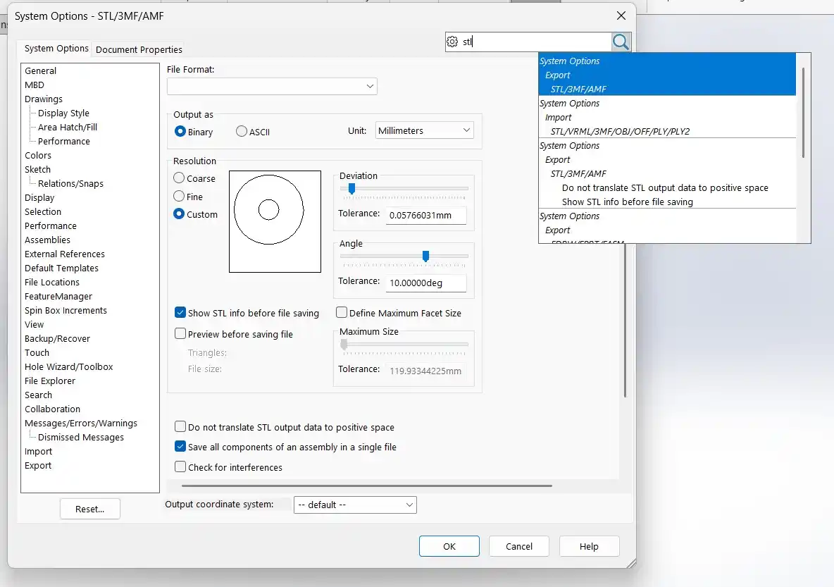
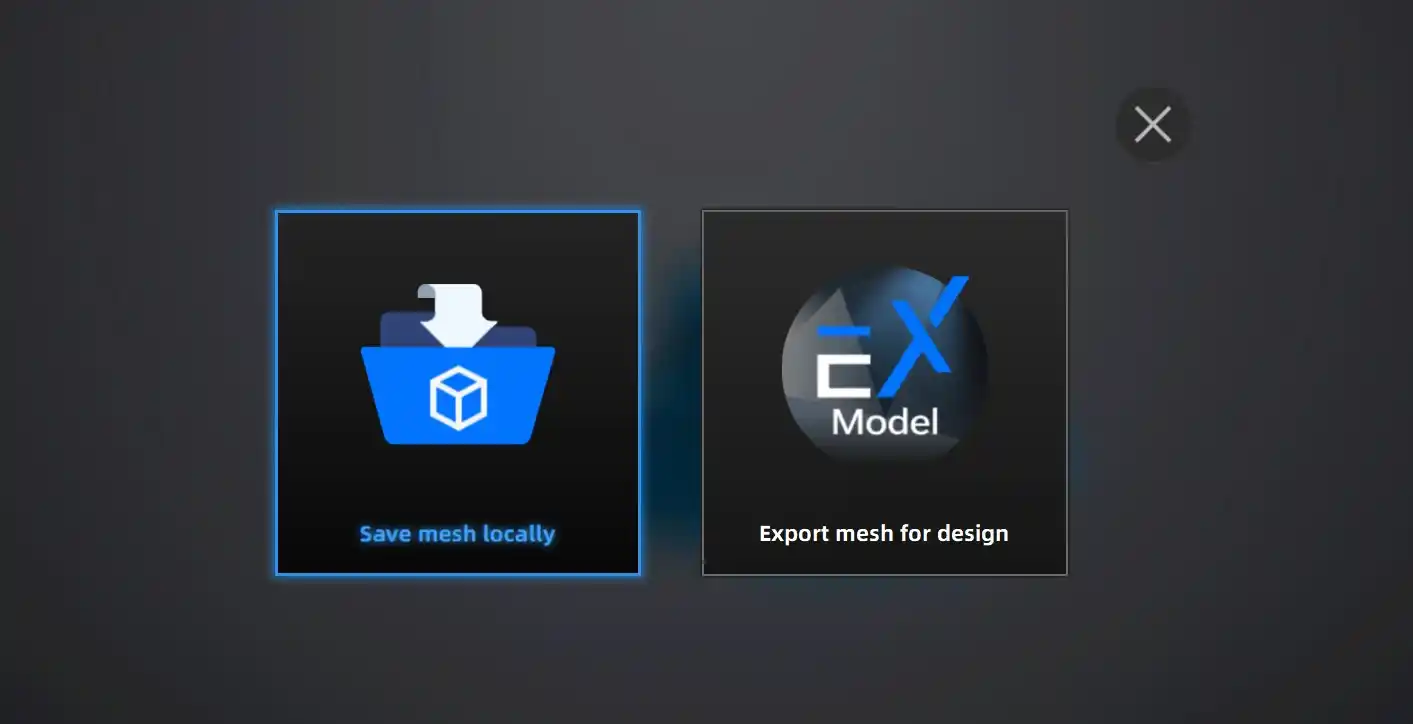
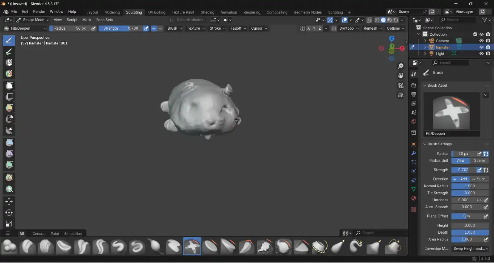
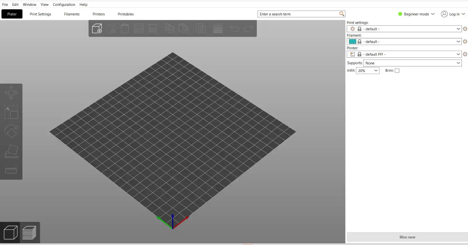
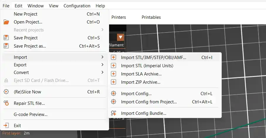
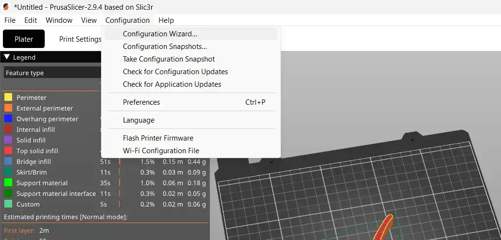
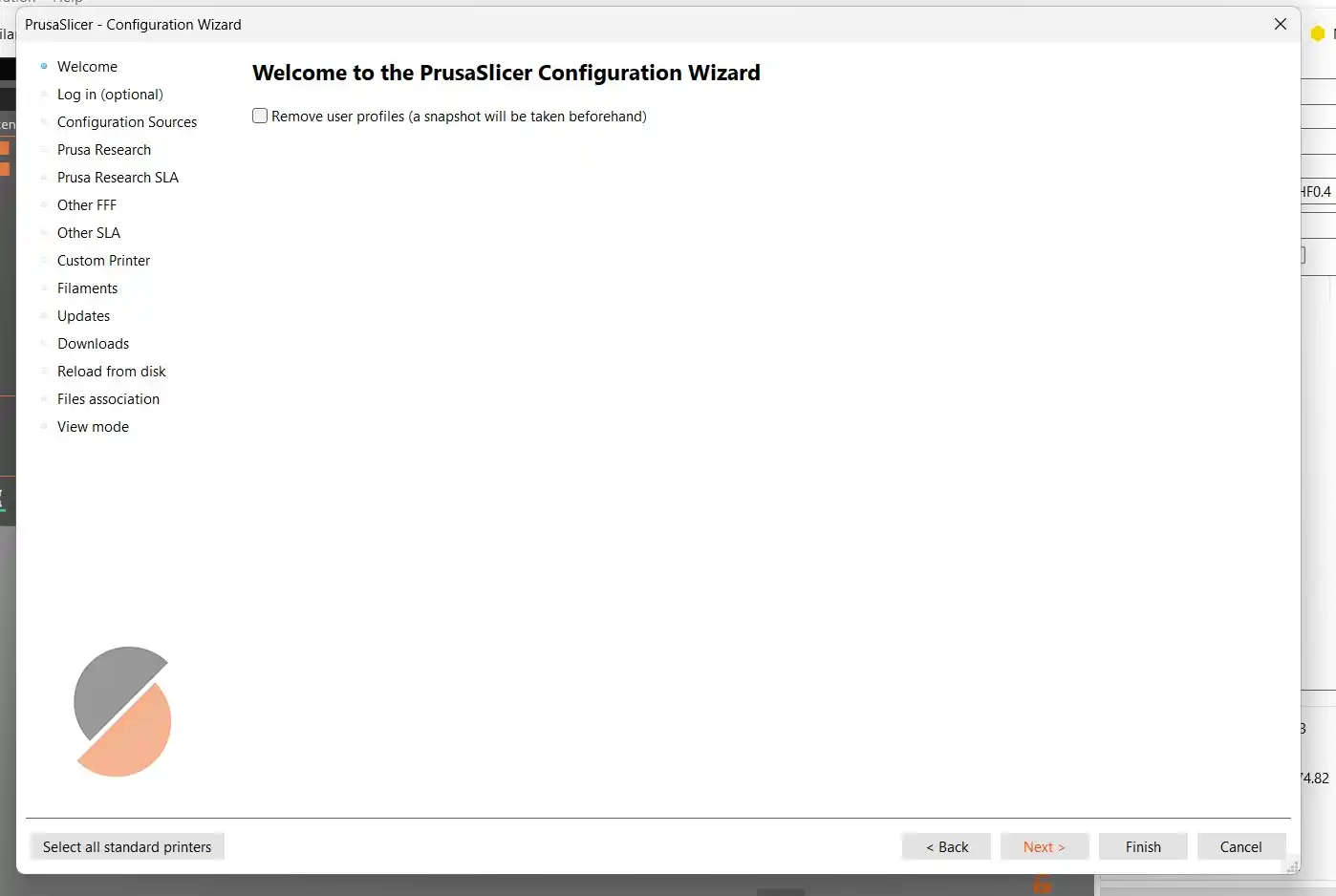
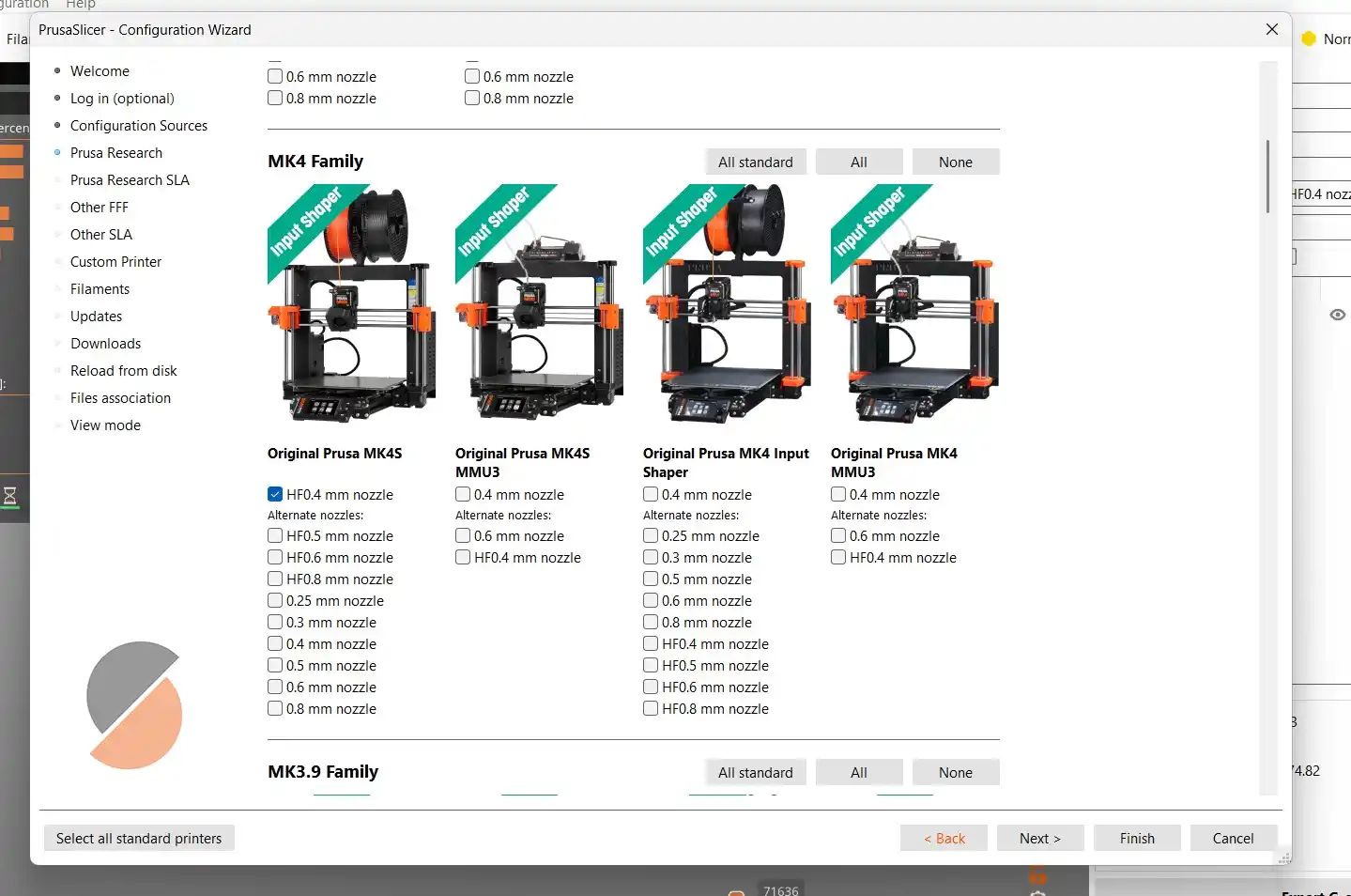
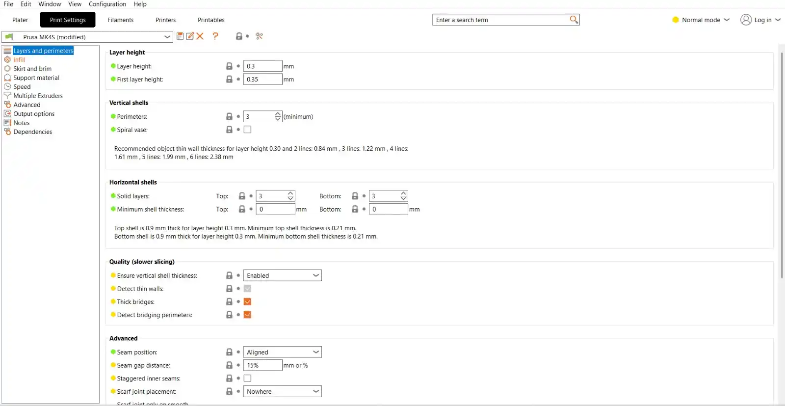
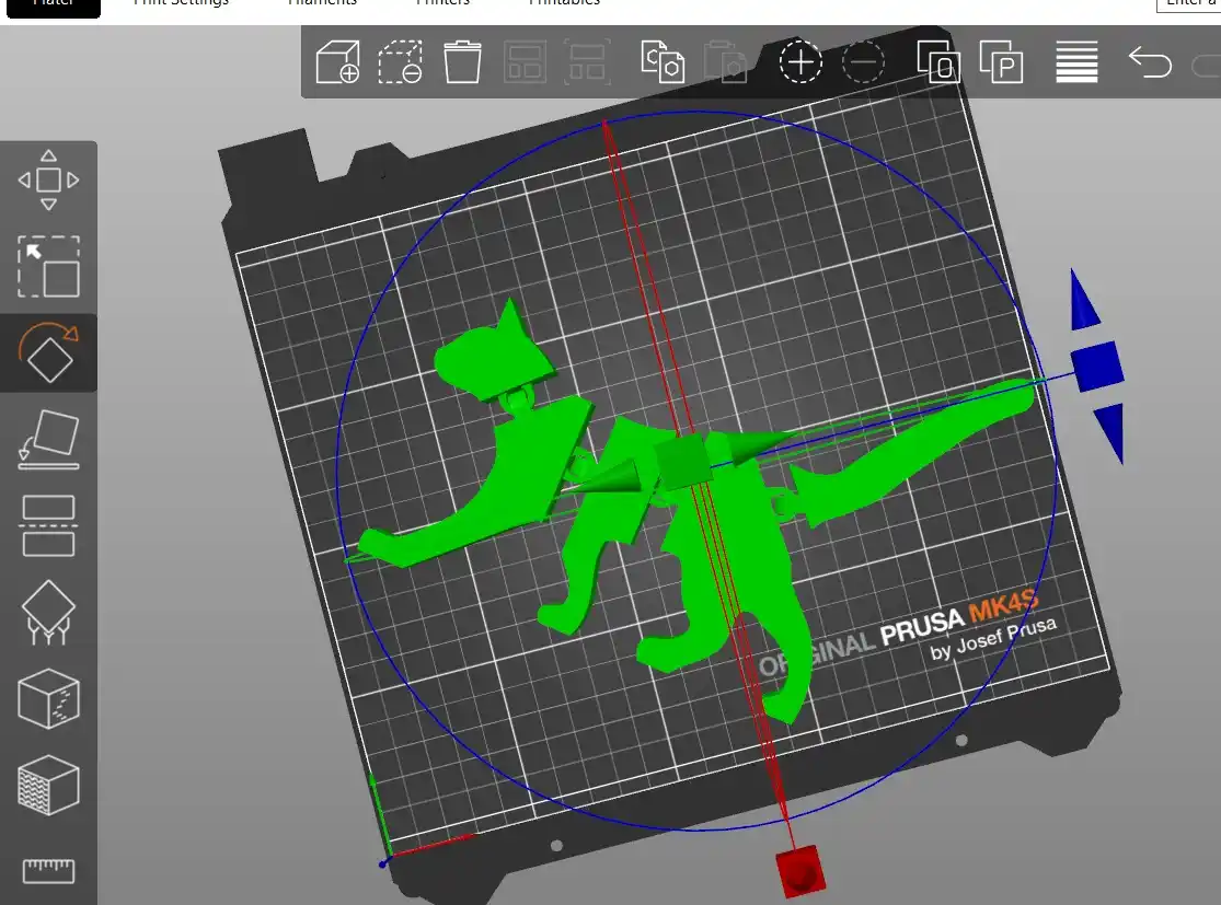
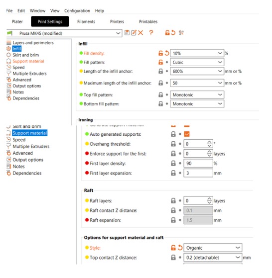
3. Software
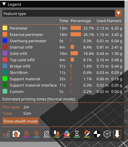
4. 3D printing
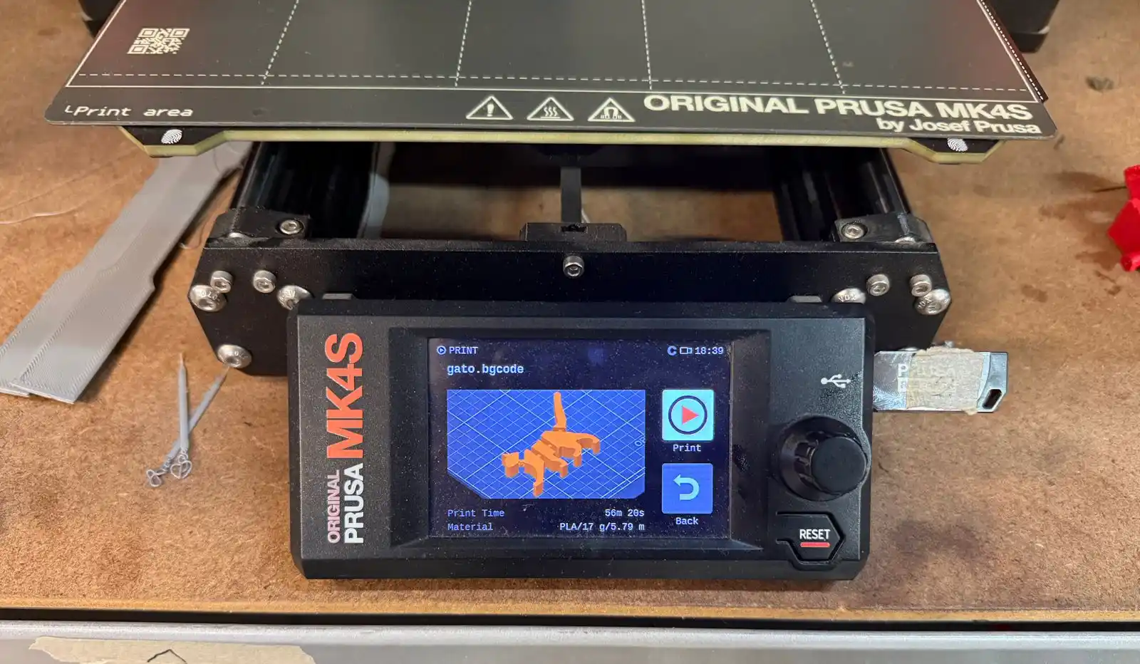
To start the printing process, I inserted the USB drive into the printer. The most recent file saved is the one that automatically appears on the screen. I selected Print, and the machine began the printing process.
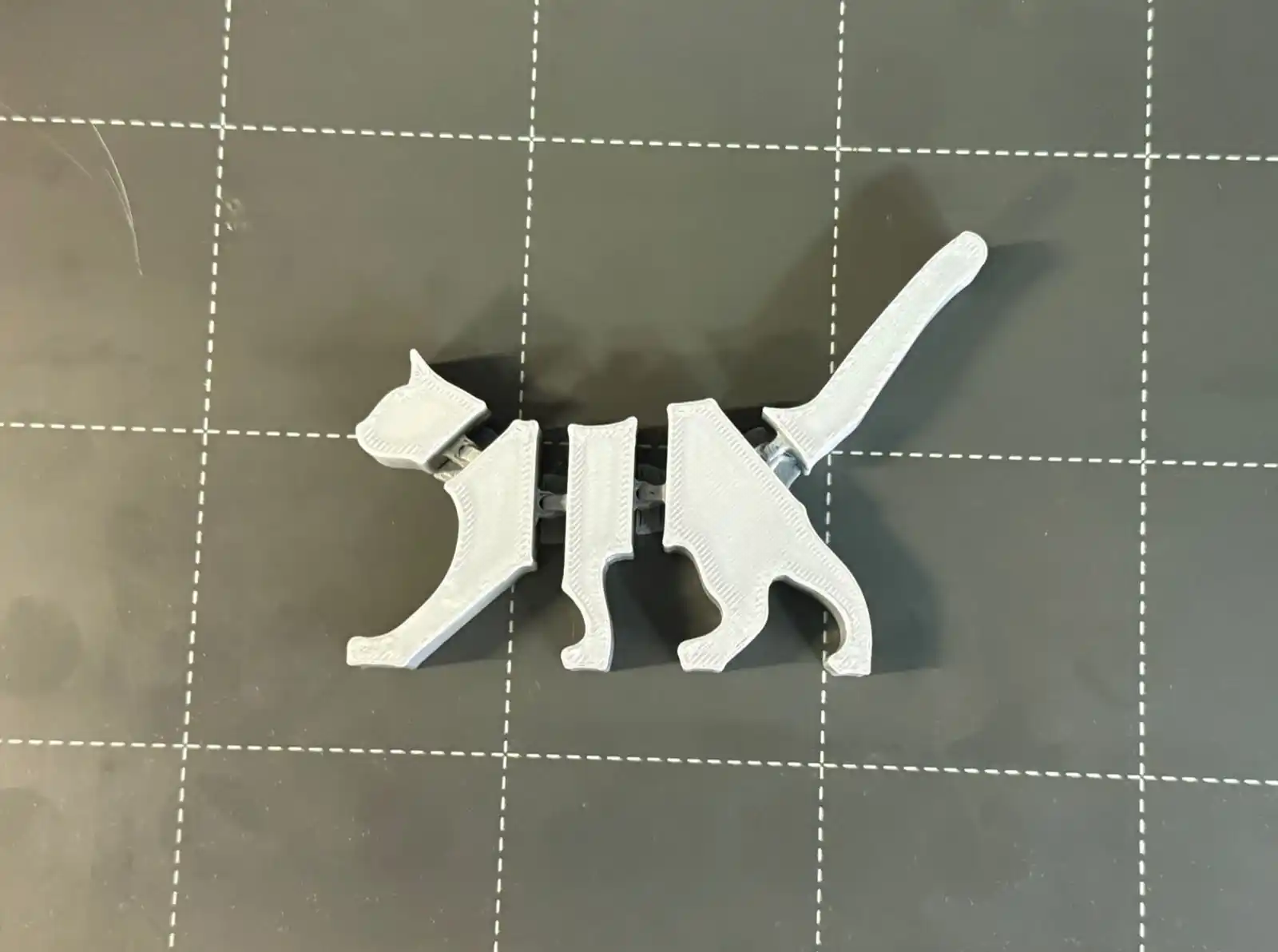
I also 3D printed my cat model in orange so it would remind me more of my cat, Jumper.