4. Embedded Programming
During this week, an individual assignment focused on the use of microcontrollers was carried out. The objective was to review the datasheet of a microcontroller to understand its operation, pins, and main characteristics. With this information, a program was developed and tested that interacts with input and output devices, in addition to establishing communication through wired or wireless connections.
For more information about microcontrollers, data sheets, and the comparative analysis of different programming languages and architectures, visit our GROUP PAGE.
1. Microcontroller
This week, I chose the Raspberry Pi Pico 2 due to the high number of output pins it offers. However, I am still deciding which will be the final board for my project, as I am evaluating two main options:
- Raspberry Pi Pico 2: It utilizes the RP2350 chip in the standard Pico family form factor.
- Seeed Studio XIAO ESP32-C3: In this case, XIAO refers to the board's form factor, which features the ESP32-C3 chip. It is an excellent choice if I require Wi-Fi or Bluetooth connectivity.
Features Comparison
| Feature | ESP32-C3 | RP2350 |
|---|---|---|
SRAM |
400 KB | 520 KB |
Flash Memory |
4 MB | 4 MB |
GPIO Pins |
11 GPIO | 26 GPIO multi-function |
Analog Inputs |
4 ADC channels | 4 ADC channels |
Communication |
UART, I²C, SPI | UART, I²C, SPI |
Languages |
Arduino, MicroPython | C/C++, MicroPython, CircuitPython |
Wireless |
Wi-Fi 2.4 GHz + Bluetooth 5.0 / BLE | None |
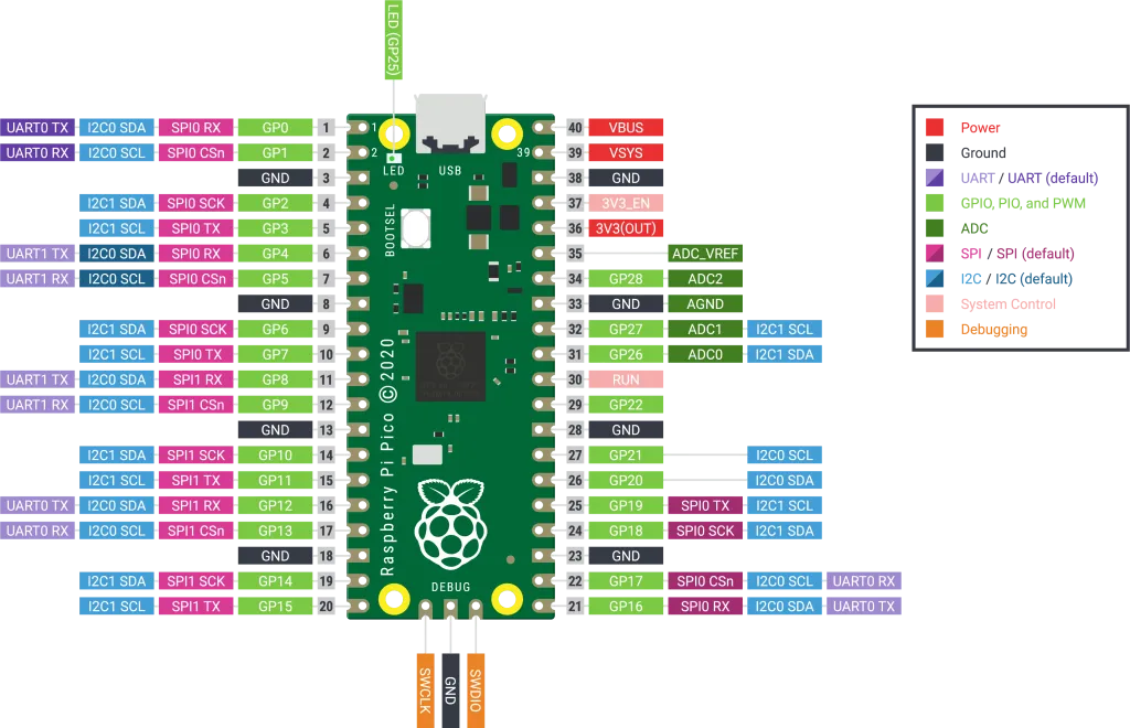
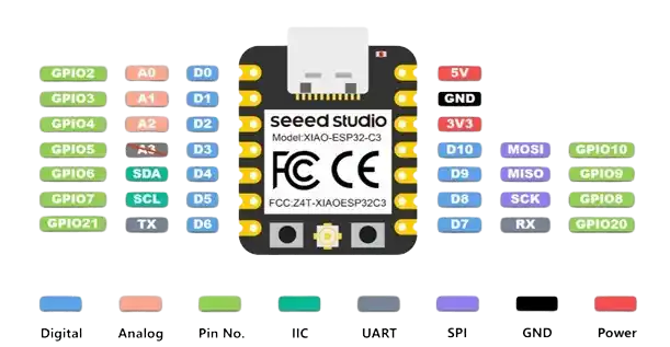
Each of the pins has different functions, which are:
- GPIO (General Purpose Input/Output): For inputs (buttons, digital sensors) or output (leds, buzzers).
- Digital Pins: Work only with two states: LOW (0V) or HIGH (3.3V).
- Analog Pins: Read continuous voltage (potentiometers, flex sensors).
- PWM: A digital signal that behaves like an analog signal (servo motors).
- UART: Simple point-to-point serial communication.
- TX → transmit
- RX → receive
- I2C: Two-wire serial communication.
- SDA → data
- SCL → clock
2. Simulation
To become more familiar with this microcontroller, I used Wokwi to simulate the same code in two languages: MicroPython and C.
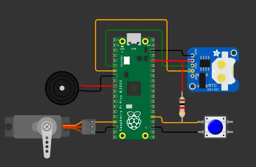
I will use a clock sensor, a motor, and a buzzer focused on my final project; when the time set by the user for the alarm is reached, the motor must start moving and the buzzer must start sounding. When the button is pressed, both things must stop.
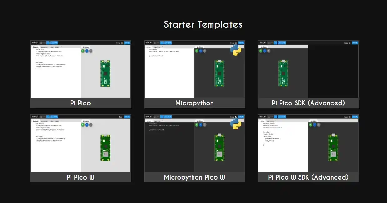
- Open Wokwi.
- Select the microcontroller.
- Select the language in which you want to program.
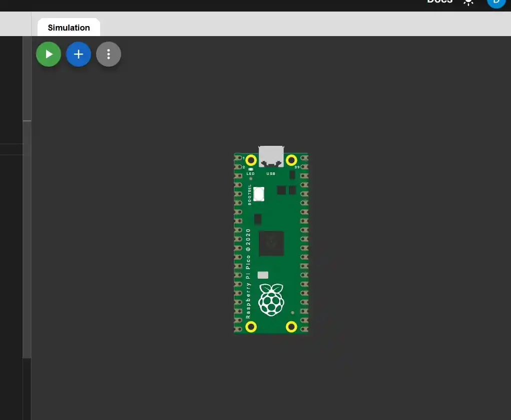
- The main tab will have code on the left and the microcontroller on the right.
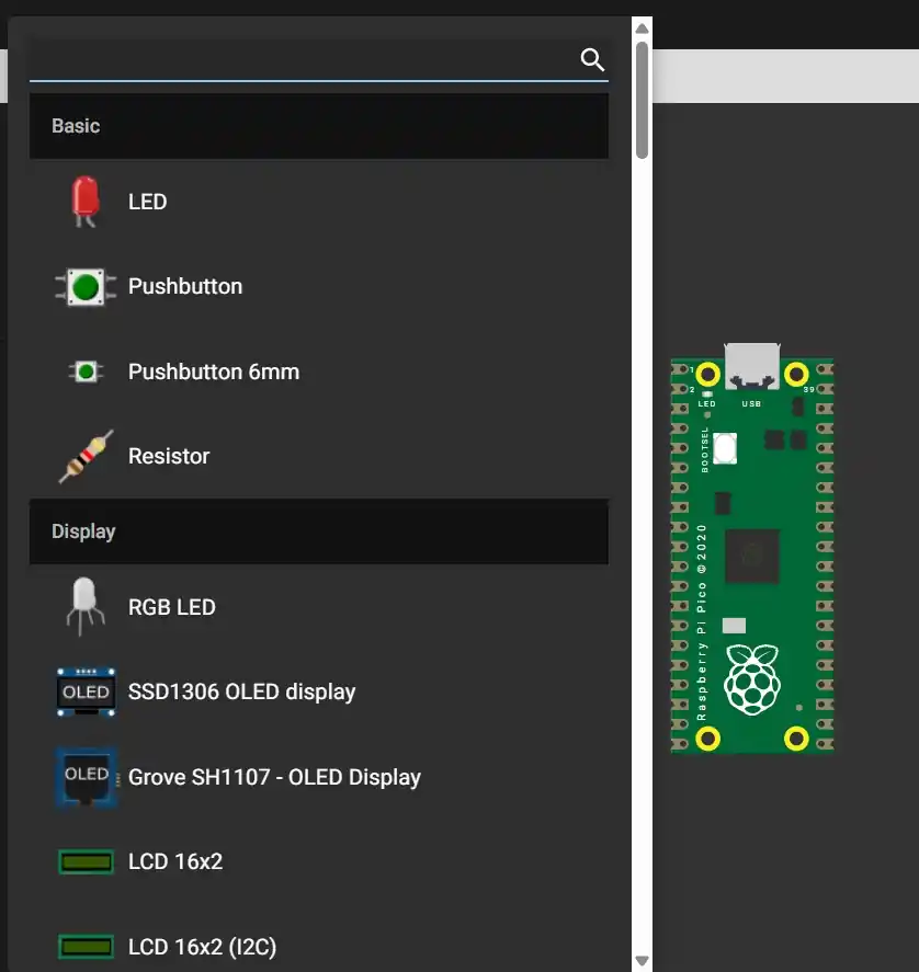
- To add more components, press the blue button with a plus sign.
- Choose which component we want to add.
- The new component will appear next to the microcontroller; to wire it, you press the component and a line will appear. To rotate the component, press the R key.
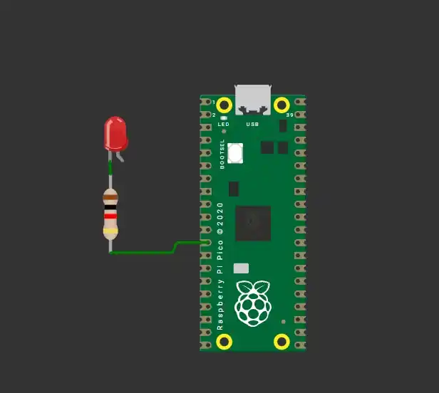
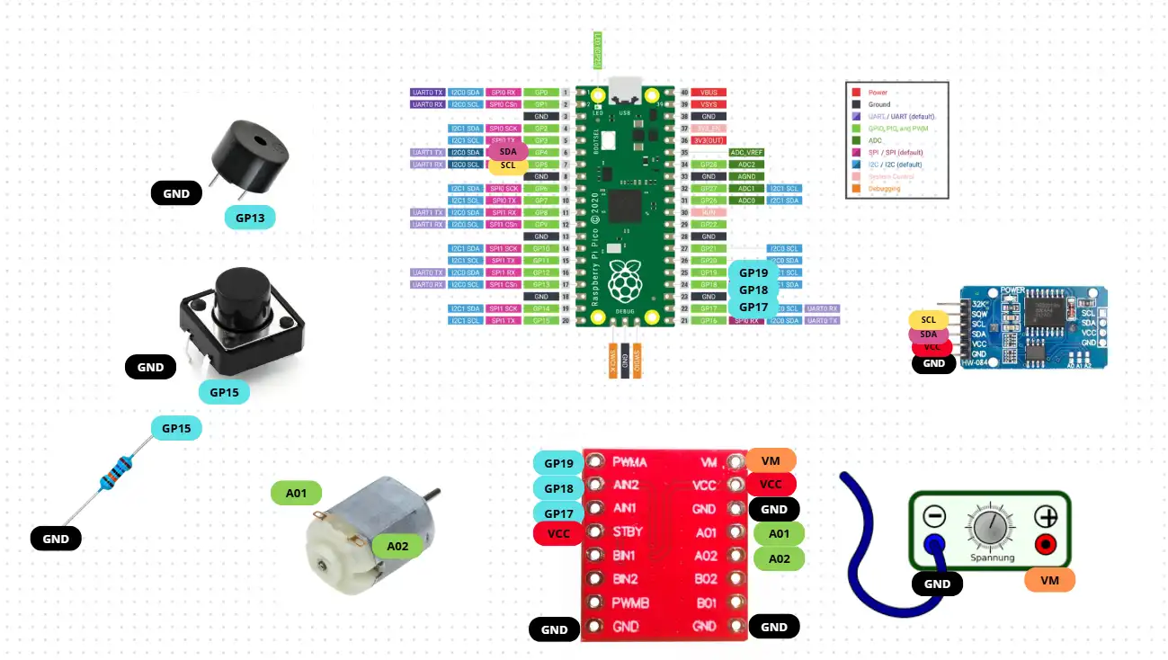
This was the connection I made:
3. Code
MicroPython
| Command | Syntax / Example | Description |
|---|---|---|
Comments |
# Single or ''' Multi ''' |
Notes that the program ignores. |
| Printing | print("HELLO WORLD") |
Displays information in the terminal. |
| Variables | string, int, float, boolean |
Space to save information (text or numbers). |
| Conditions | if, elif, else |
Executes code only if a condition is met. |
| Operators | and, or |
Used to check multiple conditions at once. |
| Loops | while, for i in range(10) |
Repeats code while true or for a set range. |
Function & Exception Handling: They are reusable blocks of code. To prevent the program from stopping when an error occurs, we use:
try:
    resultado = 10 / 0
except ZeroDivisionError:
    print("Cannot divide")
Micropython Code
from machine import Pin, PWM, I2C
import time

#-----------PINS----------
SDA_PIN = 4 # Pins to connect the DS3231 we must make sure that if they are SDA and SCL
SCL_PIN = 5
DS3231_ADDR = 0x68

SERVO_PIN = 14 # Pin to connect the servo
BUZZER_PIN = 13 # Pin to connect the buzzer
BOTON_PIN = 19 # Pin to connect the button

# ================== I2C RTC ==================
i2c = I2C(0, scl=Pin(SCL_PIN), sda=Pin(SDA_PIN), freq=100000)

# With this part of the code we convert from binary to decimal.
# The watch stores the data in two parts that are a binary number and a binary number.
# For example, 25 looks like this: 0010 (2) 0101 (5) Then it becomes val >> 4: Move everything to the right to keep only the 2.
# Then multiply it by 10 (20).
# And val & 0x0F: Delete the left side to keep only the 5. then add it and there are 25.
def bcd_to_dec(val):
    return ((val >> 4) * 10) + (val & 0x0F)

def leer_hora():
    data = i2c.readfrom_mem(DS3231_ADDR, 0x00, 3) # Timer registration
    segundos = bcd_to_dec(data[0])
    minutos = bcd_to_dec(data[1])
    horas = bcd_to_dec(data[2] & 0x3F)
    return horas, minutos, segundos

# ================== SERVO ==================
servo = PWM(Pin(SERVO_PIN)) # configure the pin for the servo with PWM
servo.freq(50)

def set_servo_position(deg):
    # Limit safe range
    if deg < 0:
        deg = 0
    if deg > 180:
        deg = 180

    # Function that helps us map the servo position from degrees to PWM units
    duty = int(1638 + (deg / 180) * 6553)
    servo.duty_u16(duty)

# ================== BUZZER ==================
buzzer = PWM(Pin(BUZZER_PIN))

def set_buzzer_freq(freq): # give it specific sound commands.
    if freq == 0:
        buzzer.duty_u16(0) # Line to prevent our buzzer from sounding
    else:
        buzzer.freq(freq)
        # This line calculates how long a clock cycle needs to be to fit exactly the amount of "vibrations" (freq) you want to hear in one second.
        buzzer.duty_u16(32768)  # 50%

# ================== BUTTON ==================
boton = Pin(BOTON_PIN, Pin.IN, Pin.PULL_UP) # We initialize our pin as input

# ================== ALARM CONFIG ==================
# For the user to enter the time
print("Hamster Alarm Configuration")
h_alarma = int(input("Hour (0-23): "))
m_alarma = int(input("Minute (0-59): "))

print(f"Alarm set at {h_alarma:02d}:{m_alarma:02d}")

alarma_disparada = False

# ================== MAIN LOOP ==================
pos_izq = 20
pos_der = 160

while True:
    # Read the RTC
    horas, minutos, _ = leer_hora()

    # activate the alarm at the time the user logged in
    if horas == h_alarma and minutos == m_alarma and not alarma_disparada:
        alarma_disparada = True
        print("Alarm activated!")

    if alarma_disparada:
        # if the alarm is activate the buzzer and the servo are activated
        set_servo_position(pos_izq)
        set_buzzer_freq(1000)
        time.sleep(0.2)

        set_servo_position(pos_der)
        set_buzzer_freq(1500)
        time.sleep(0.2)

        # if the button is activated the buzzer and the servo are desactivated
        if boton.value() == 0:
            alarma_disparada = False
            set_buzzer_freq(0)
            set_servo_position(90)
            print("Hamster caught! Alarm off.")
            time.sleep(60)

    else:
        print(f"Current time: {horas:02d}:{minutos:02d}")
        time.sleep(1)
C
| Command | Syntax / Example | Description |
|---|---|---|
Comments |
// Single or /* Multi */ |
Documentation inside the code. |
| Variables | string, int, float, boolean |
Typed space to save information. |
| Conditions | if (condition) { // code } |
Uses curly braces { } to enclose the code. |
| Operators | && (AND), || (OR), ! (NOT) |
Logical operators to invert or combine values. |
| While Loop | while (condition) { } |
Repeats while the condition is true. |
| For Loop | for (int i=0; i < 10; i++) { } |
The syntax is: for(start; condition; increment). |
Example of a For Loop in C :
    for (int i = 0; i < 10; i++) {
        printf("%d\n", i); //Prints from 0 to 9
    }
C Code
#include </stdio.h>
#include "pico/stdlib.h"
#include "hardware/i2c.h"
#include "hardware/pwm.h"

/* -------------PINS------------ */
#define I2C_PORT i2c0
#define SDA_PIN 4 /*Pins to connect the DS3231 we must make sure that if they are SDA and SCL */
#define SCL_PIN 5
#define DS3231_ADDR 0x68

#define SERVO_PIN 13  /*Pin to connect the servo */
#define BUZZER_PIN 7  /*Pin to connect the buzzer */
#define BOTON_PIN 19 /*Pin to connect the button*/

// With this part of the code we convert from binary to decimal.

/* The watch stores the data in two parts that are a binary number and a binary number.
For example, 25 looks like this: 0010 (2) 0101 (5) Then it becomes val >> 4: Move everything to the right to keep only the 2.
Then multiply it by 10 (20).
And val & 0x0F: Delete the left side to keep only the 5. then add it and there are 25. */
uint8_t bcd_to_dec(uint8_t val) {
    return ((val >> 4) * 10) + (val & 0x0F);
}

/* ------------SERVO----------------*/
void setup_servo(uint pin) {
    gpio_set_function(pin, GPIO_FUNC_PWM);   //configure the pin for the servo with PWM
    uint slice = pwm_gpio_to_slice_num(pin);

    pwm_set_clkdiv(slice, 64.0f);
    pwm_set_wrap(slice, 39062);
    pwm_set_enabled(slice, true);
}

void set_servo_position(uint pin, int degrees) {
    uint32_t duty = (degrees * 2000 / 180) + 1000; // Function that helps us map the servo position from degrees to PWM units
    pwm_set_gpio_level(pin, duty);
}

/* ------------BUZZER------------- */
void setup_buzzer(uint pin) {
    gpio_set_function(pin, GPIO_FUNC_PWM);
    uint slice = pwm_gpio_to_slice_num(pin);

    pwm_set_clkdiv(slice, 4.0f);      // Reduce base frequency
    pwm_set_wrap(slice, 31250);       // Audible base
    pwm_set_enabled(slice, true);
}

void set_buzzer_freq(uint pin, uint freq) {     //give it specific sound commands.
    uint slice = pwm_gpio_to_slice_num(pin);

    if (freq == 0) {
        pwm_set_gpio_level(pin, 0);   //Line to prevent our buzzer from sounding
        return;
    }

    uint32_t wrap = 125000000 / 4 / freq;
    pwm_set_wrap(slice, wrap);
    pwm_set_gpio_level(pin, wrap / 2); /* This line calculates how long a clock cycle needs to be to
    fit exactly the amount of "vibrations" (freq) you want to hear in one second.*/
}

/* --------------- MAIN ------------------- */
int main() {
    stdio_init_all();

    i2c_init(I2C_PORT, 100000);
    gpio_set_function(SDA_PIN, GPIO_FUNC_I2C);
    gpio_set_function(SCL_PIN, GPIO_FUNC_I2C);
    gpio_pull_up(SDA_PIN);
    gpio_pull_up(SCL_PIN);

    setup_servo(SERVO_PIN);
    setup_buzzer(BUZZER_PIN);

    gpio_init(BOTON_PIN);
    gpio_set_dir(BOTON_PIN, GPIO_IN);
    gpio_pull_up(BOTON_PIN);

    //We initialize our pins as output or input

    int h_alarma, m_alarma;
    bool alarma_disparada = false;

    // For the user to enter the time
    printf("Configuración de Alarma Hamster\n");
    printf("Hora (0-23): ");
    scanf("%d", &h_alarma);
    printf("Minuto (0-59): ");
    scanf("%d", &m_alarma);
    printf("Alarma fijada a las %02d:%02d\n", h_alarma, m_alarma);

    uint8_t reg = 0x00;
    uint8_t data[3];
    //Timer registration

    while (true) {
        // Read the RTC (DS1307)
        i2c_write_blocking(I2C_PORT, DS3231_ADDR, ®, 1, true);
        i2c_read_blocking(I2C_PORT, DS3231_ADDR, data, 3, false);

        uint8_t minutos = bcd_to_dec(data[1]);
        uint8_t horas = bcd_to_dec(data[2] & 0x3F);

        //activate the alarm at the time the user logged in
        if (horas == h_alarma && minutos == m_alarma && !alarma_disparada) {
            alarma_disparada = true;
            printf("¡Alarma activada!\n");
        }

        if (alarma_disparada) {
            // if the alarm is activate the buzzer and the servo are activated
            set_servo_position(SERVO_PIN, 20);
            set_buzzer_freq(BUZZER_PIN, 1000);
            sleep_ms(200);

            set_servo_position(SERVO_PIN, 270);
            set_buzzer_freq(BUZZER_PIN, 1500);
            sleep_ms(200);

            // if the button is activated the buzzer and the servo are desactivated
            if (gpio_get(BOTON_PIN) == 0) {
                alarma_disparada = false;
                set_buzzer_freq(BUZZER_PIN, 0);
                set_servo_position(SERVO_PIN, 90);
                printf("Alarma apagada.\n");
                sleep_ms(60000);
            }
        } else {
            printf("Hora actual: %02d:%02d\n", horas, minutos);
            sleep_ms(1000);
        }
    }
}
Video Simulation (WARNING WITH THE SOUND!!!)
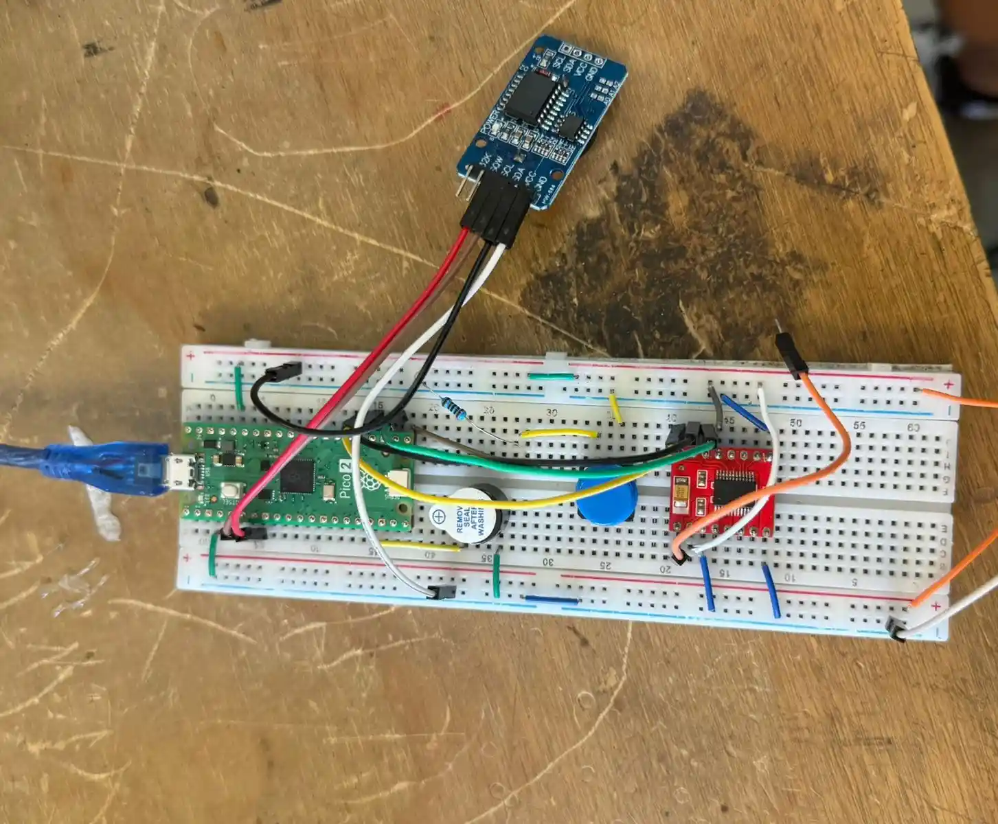
4. Construction
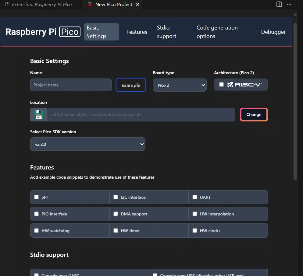
To have it physically, I used Visual Studio Code, and to be able to program my Pi Pico 2, I did the following:
- Open Visual Studio Code.
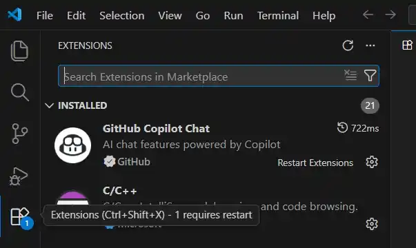
- Go to the extensions menu located on the left side of the Visual home screen.
- Search for the Raspberry Pi Pico extension and install it.
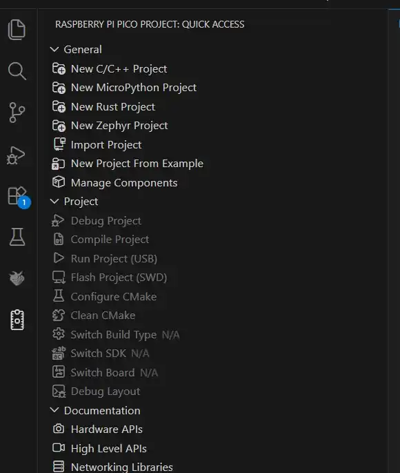
- Wait a moment and the symbol of a Raspberry Pi Pico will appear in the menu; select the icon and select the language in which you want the file.
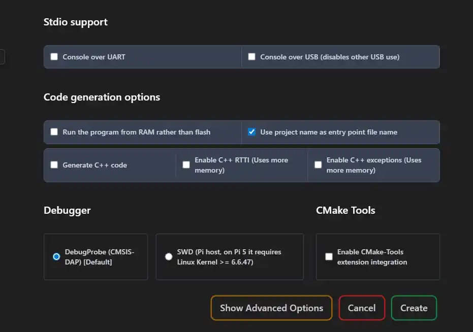
- Change the name of the file.
- At the bottom, press the Create button and that's it; we can now program to upload to our microcontroller.

Schematic
I replaced the servo from the simulation with a small DC motor in the physical build, so I added an H-Bridge to the circuit. These are the final connections.