Week Context
What I knew before:
- At that point, I only knew how to model in SolidWorks and Catia.
- I did not know how to use Blender.
- I had never worked with PET or styrene.
- I had never used a thermoforming machine.
Week context: For my Industrial Design Workshop course, I built a prototype of a salt and pepper shaker set out of MDF, giving it a smooth and professional finish. The professor asked us to create a Display — meaning the stand on which the prototype would be mounted — as the conceptual presentation piece for the salt and pepper shaker. The idea was to make the display in the shape of a cloud.
Why this week is different: Although we had already covered topics like computer-aided 3D design and 3D printing, this week was different as it was the first time we used the thermoforming machine or any system that required applying a vacuum to our process.
Planning and Design
To achieve this, the first step was to conceptualize how we wanted the Display to look. We described our ideas to ChatGPT and it provided the following reference images.
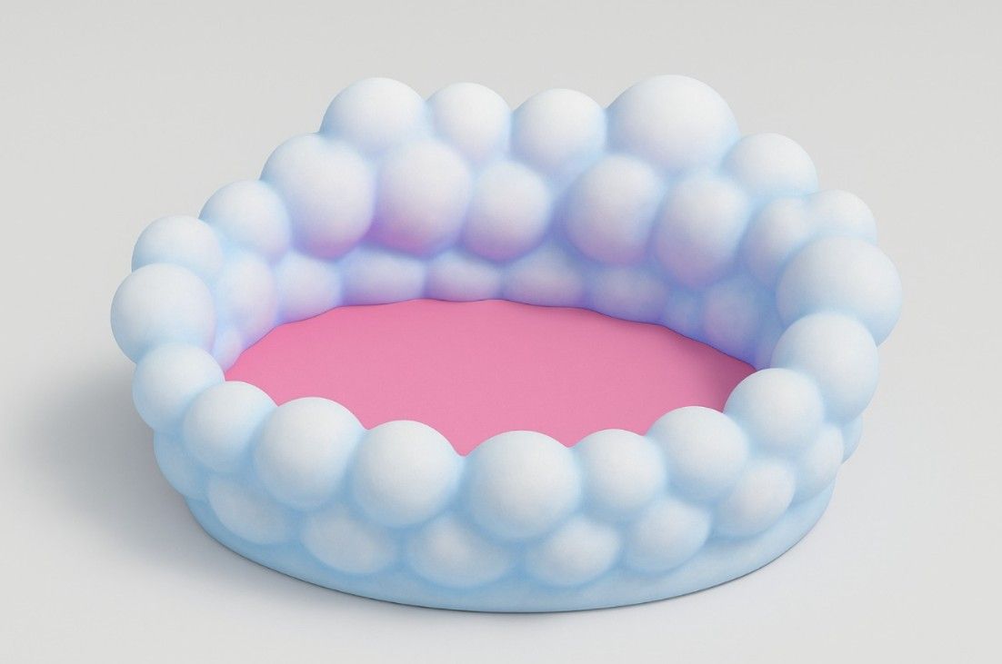
Reference image 1
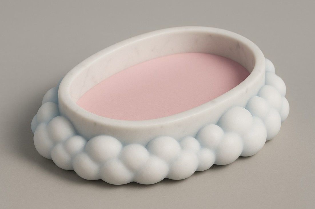
Reference image 2
I then tried modeling different pieces in SolidWorks; however, I was not happy with the results, and the sharp peaks they produced would have made it very difficult for the thermoforming machine to replicate them.
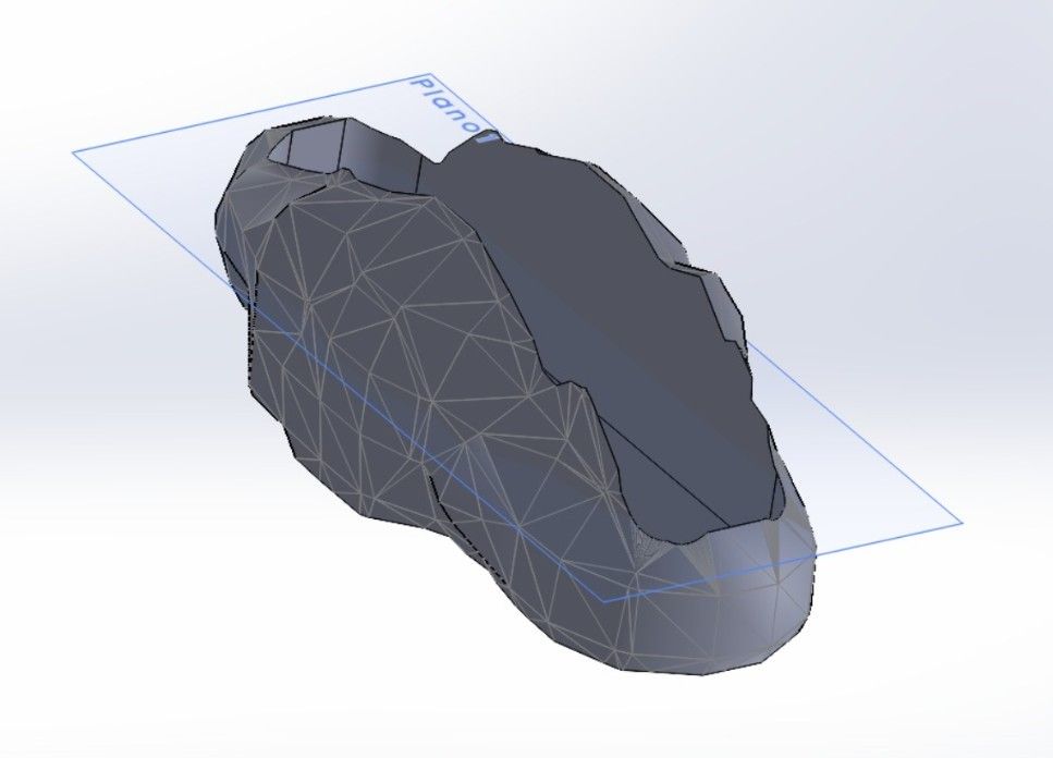
SolidWorks attempt 1
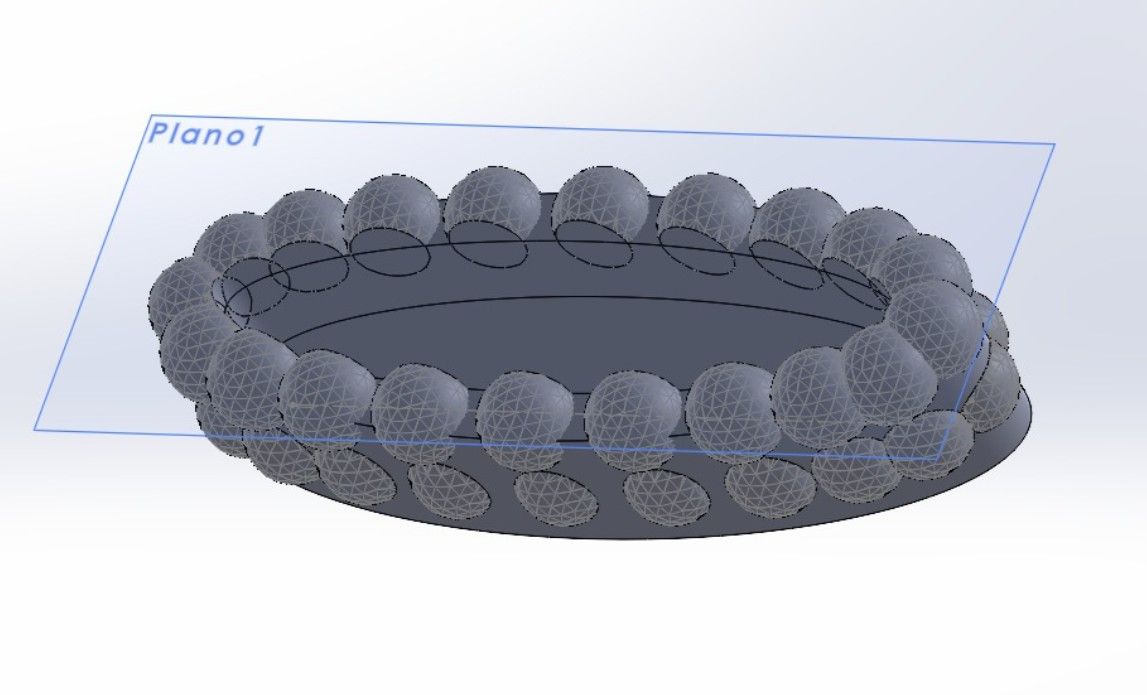
SolidWorks attempt 2
Note: Creating organic shapes in SolidWorks is much harder because the program is too parametric — everything requires a specific measurement.
Blender
In order to have more flexibility in the design creation, I proceeded to model it in Blender.
Note: I did not record a video or take photos of my modeling process for this piece; however, I referenced the following YouTube tutorials:
- Como hacer nubes en Blender | Tutorial fácil en Español | Maritdoodles — How to create clouds in Blender.
- Make Stunning Clouds FAST in Blender! — How to create clouds with Blender.
This is the cloud-shaped design I arrived at in Blender:
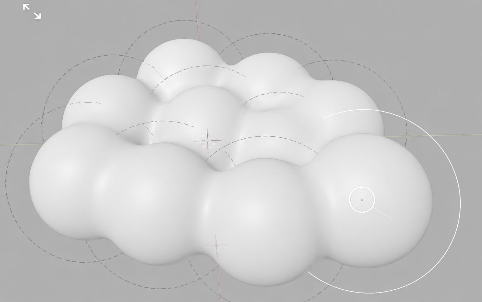
Cloud-shaped design in Blender.
SolidWorks & Printing
I then imported the Blender model into SolidWorks and added the corresponding holes so the salt and pepper shakers could stand and be held in place.
Note: If there are surfaces where I need the material to sink down, it is necessary to add holes in that area of the model so that the thermoforming machine can create suction when the vacuum is applied.
The holes do not need to be very large, but the bigger the better. In fact, if the geometry is complex and adding holes makes printing difficult, they can be drilled in after printing using a drill press or bench drill.
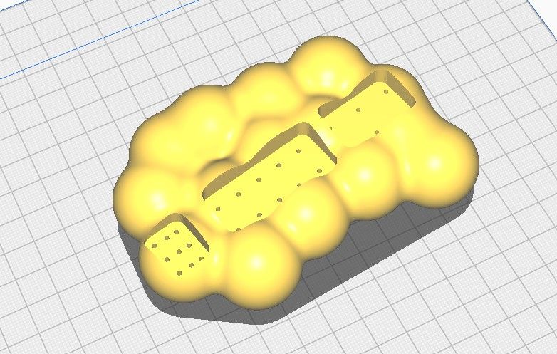
Model imported into SolidWorks with the holes added.
From there, I brought it into Ultimaker Cura with the following parameters:
Parameters in Ultimaker Cura.
I then printed it on a Creality Ender 3v:
Printing on the Creality Ender 3v.
This is how the final 3D-printed piece turned out:
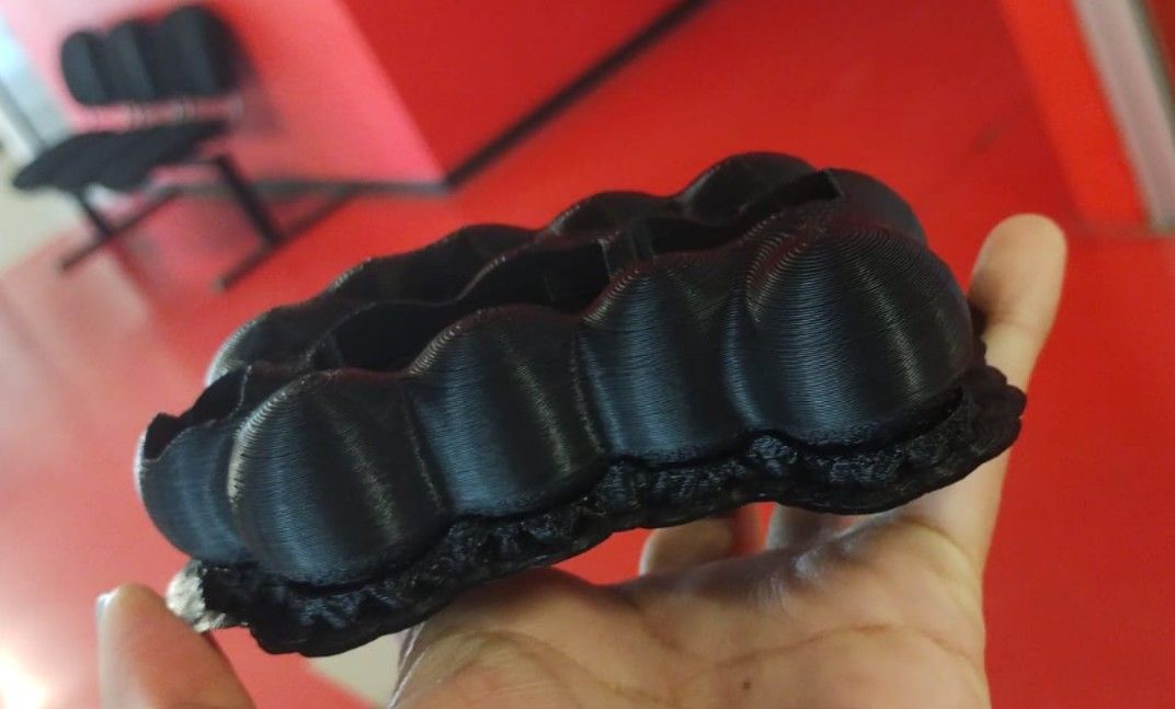
Final 3D-printed piece.
Thermoforming
Thermoforming Process
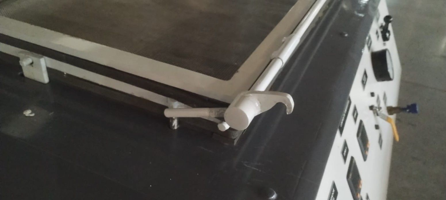
Step 2 — Raise the frame
Raise the frame holding the PET using the knob on the far right side of the machine.
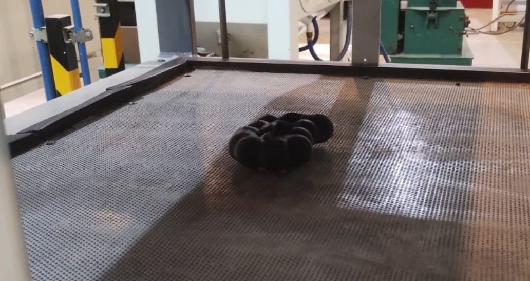
Step 3 — Place the piece
Place the piece at the center of the frame.
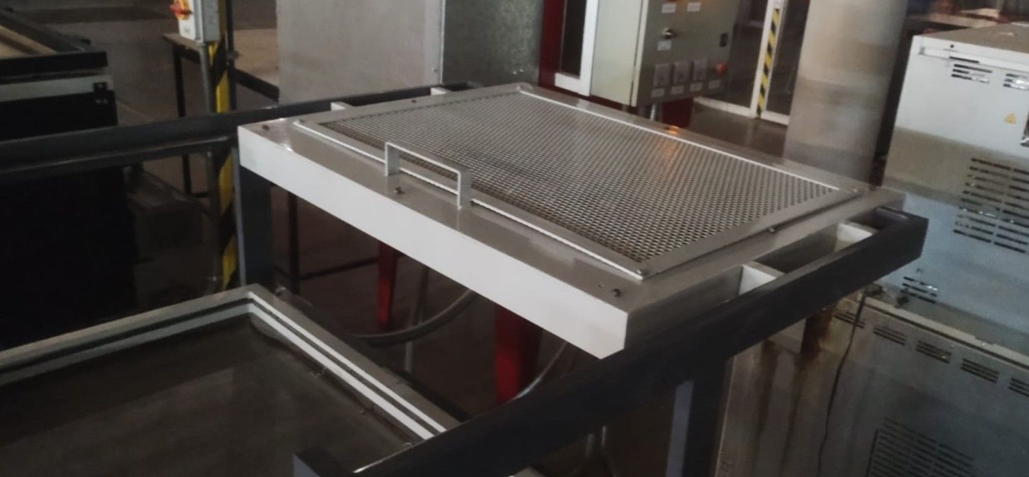
Step 4 — Move the heating element
Slide the heating element — located at the very top of the machine — directly over the raised PET frame.
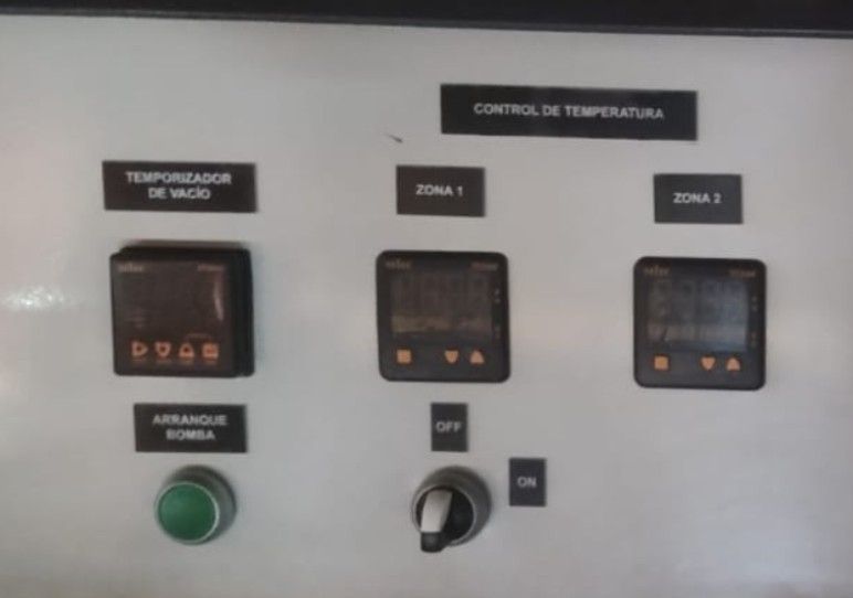
Step 5 — Turn on the machine
Turn on the machine using the green button. Then switch the black knob to its right to the On position so the heating element begins to heat the PET.
Note: To know when the PET has reached the correct temperature, look for a small "belly" or sag forming at the center of the PET sheet.
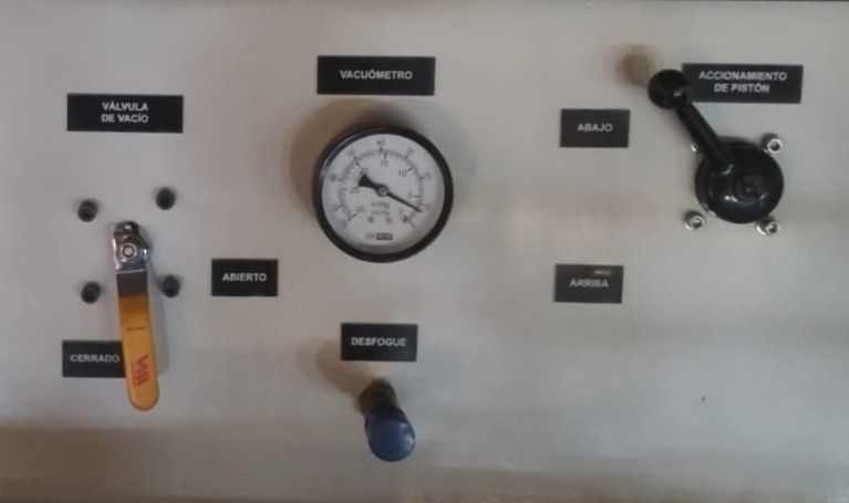
Step 7 — Open the vacuum valve
Immediately after, turn the yellow key of the "Vacuum Valve" from "Closed" to "Open".
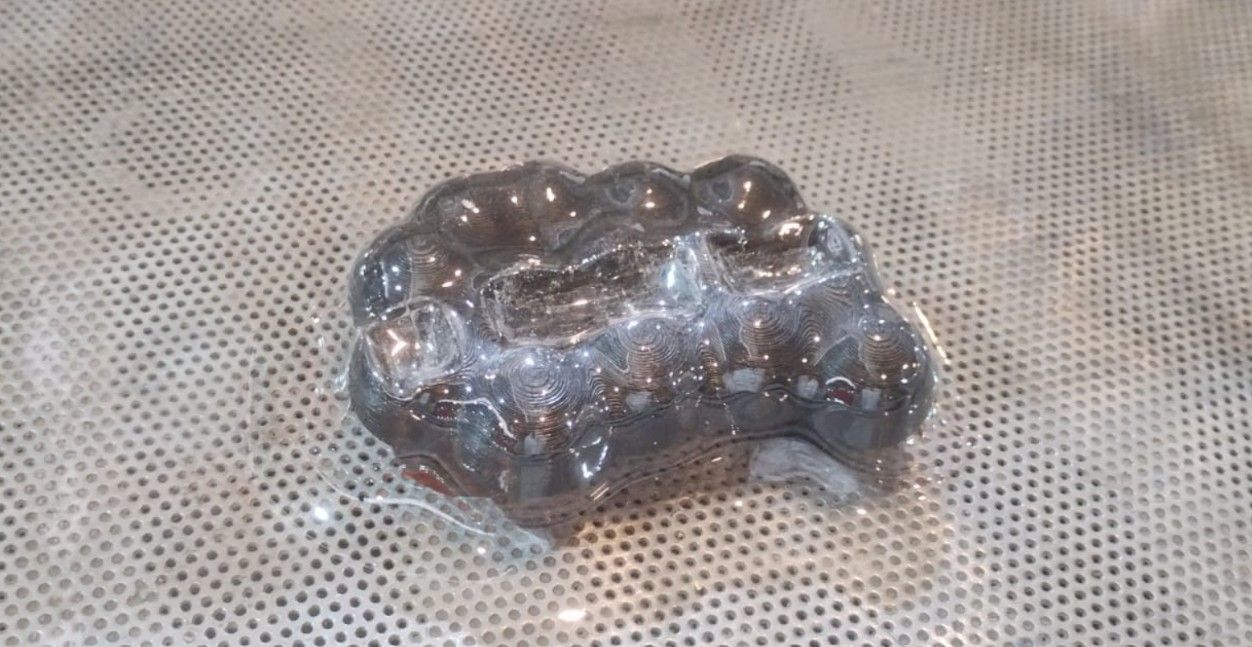
Step 8 — Remove the piece
Once the PET has cooled, open the frame to remove the material and return everything to its original state.
This is how the piece turned out.
Thermoforming temperature
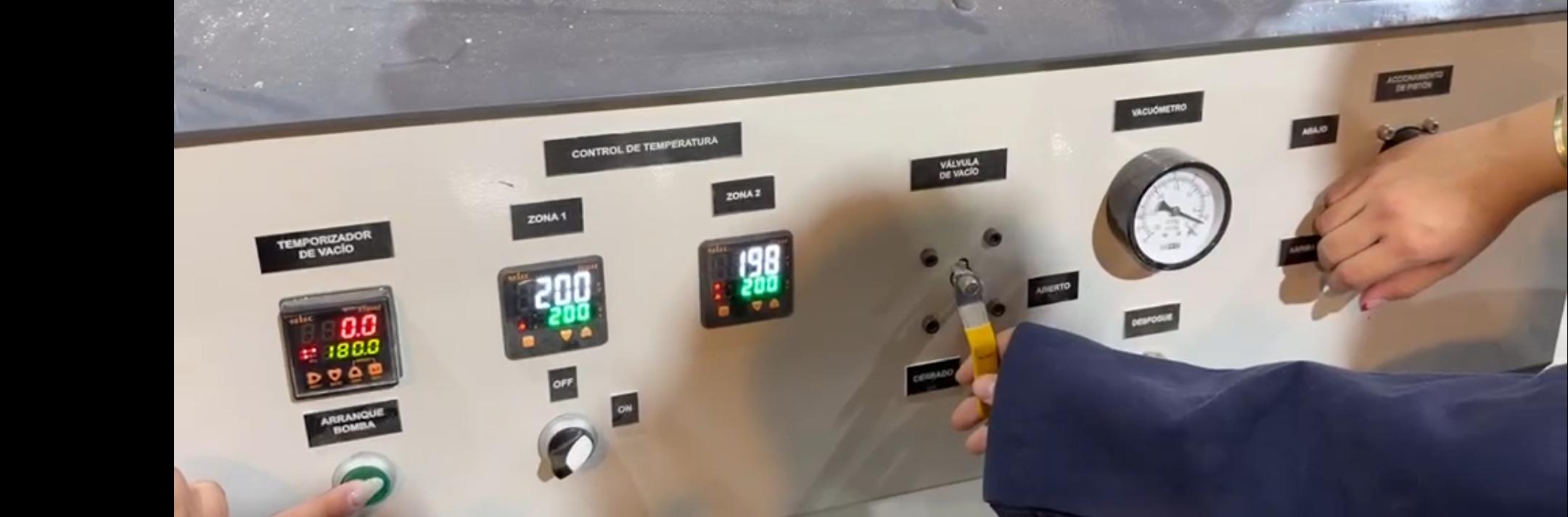
This is the temperature at which the thermoforming was done in the machine.
Temperature Used: First zone: 200°C, Second zone: 198°C and vacuum pressure timer: 180 seconds.
Post-Processing and Result
The piece, once used as a display, appeared transparent; however, this made it difficult to see the details. To fix this, we painted the inside of the piece with white spray paint.
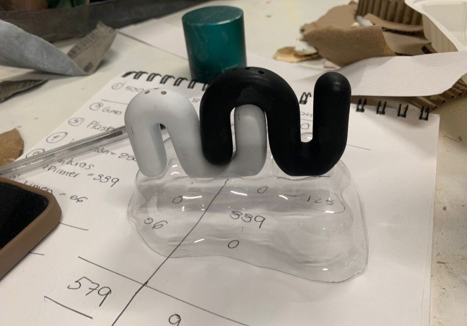
Piece before painting.
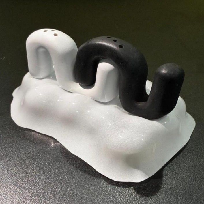
Final result as a display.
What I learned this week:
- I learned that SolidWorks, being too parametric, is not the ideal tool for creating organic shapes like clouds, since every feature requires a specific measurement. For this type of geometry, Blender offers much more flexibility.
- I learned to use Blender for the first time to model an organic cloud-shaped form, using YouTube tutorials as a guide.
- I understood the importance of adding holes to the 3D model for thermoforming: on surfaces where the material needs to sink, holes allow the vacuum to form correctly. The bigger the holes, the better; and if the geometry is too complex to add them during printing, they can be drilled in afterward using a bench drill.
- I learned to operate the thermoforming machine from start to finish: correctly placing the PET on the frame without gaps, identifying the right temperature by watching for a small "belly" sag at the center of the PET sheet, lowering the material onto the piece, and opening the vacuum valve at the right moment.
- I learned that the thinner the PET, the better it captures the shape — but it should not be too thin, as it can develop holes if it overheats.
- I discovered that a transparent thermoformed piece does not show details well, and that painting the inside with white spray paint produces a much more professional and visible display.
- I worked with PET and styrene as thermoforming materials for the first time.
Files I used this week
Note: Unfortunately, when I did this work, it was done as a team for a class, and we didn't save the original Blender document or the STL file. However, if anyone wants to replicate it, it is very easy, and it can be reproduced using the Blender videos I attached to my page.
It is only important to remember: in the areas that require more suction, holes need to be made in that part.
Thermoforming_Files.zip
Thermoforming Files
The following files are included in the package:
- 3_to print.gcode: G-Code file ready to print on the Creality Ender 3v.