Export Formats
When working with 3D models, the file format you choose depends on your end goal — whether it's printing, modifying, or rendering. Below are the main formats used in this week's workflow:
| Format | Use |
|---|---|
| STL | Standard format for 3D printing (triangle mesh). It is the most used for sending files to the slicing software (Slicer). |
| STEP | High-precision exchange format. Used to transfer solid models between different CAD softwares while maintaining editable geometry. |
| OBJ | For modifications in Blender or Rhino. It contains mesh information and is ideal for handling textures and 3D scans. |
Softwares
| Softwares | Description |
|---|---|
| Ultimaker Cura | One of the most popular open-source softwares for preparing 3D models (slicing). It allows configuring critical parameters such as layer height, infill, and supports for printing. It is compatible with a wide range of FDM printers and stands out for its intuitive interface. |
| Prusa Slicer | Software based on Slic3r, ideal for Prusa printers. It offers advanced control over the model geometry; in my case, I used it specifically to configure my piece for multi-color printing, taking advantage of its layer-based filament change tools. |
| Anycubic | Specialized software for the resin printers (SLA/DLP) available at the university. Clicking the name starts the direct download. It is essential for generating .pwmo files or similar required for photopolymerization technology. |
Ultimaker Cura
Ultimaker Cura — preferably do not log in, as it is rarely used.
Setup steps
- Non Ultimaker printer
- No network
- Search for the printer; in my case, I mostly use the "Creality Ender-3 V3 SE"
- Add printer
Navigation
- Right click: Rotate
- Scroll wheel: Zoom
- Light blue area: Correctly attached to the print bed
- Red parts: Areas requiring supports
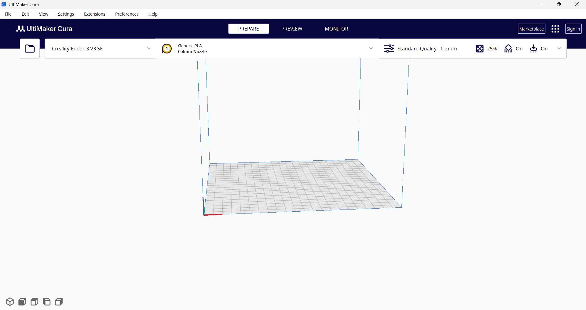
This is how the Ultimaker Cura interface looks like.
Parameters to modify
| Parameter | Description / Values |
|---|---|
| Quality | The smaller the layer height, the better the resolution, but it takes longer.
Minimum layer height:
|
| Walls | Provides better mechanical properties (especially for vertical forces).
|
| Infill (orange color) | Recommendation: 10% to 20% |
| Material | Temperature parameters [Research for other materials]:
|
| Speed (mm/s) | Up to 150 or 220. The higher the speed, the more likely errors may occur. |
| Supports | Changing the orientation of the piece can help minimize them. |
| Build plate adhesion | Recommended: Brim or Raft (Raft adds 3 layers, providing high stability but consuming more material). |
| Fuzzy skin | Wrinkled texture (useful for hiding errors, but not for structural parts). |
Prusa Slicer
Used for multi-color printing since we have this printer at the node.
- Layer height
- Perimeters = Walls
Anycubic (Beto's Program)
For resin 3D printing.
Preparing the printer
Two printers were used: a basic one allowing only one filament color, and another one used for printing my assembly. The filament used was PLA, and only one color was used.
Steps to calibrate the printer:
- Check if the bed is leveled.
- Adjust the nozzle height (0.1 mm is a good starting point).
- Run a calibration print (e.g., a calibration cube).
- Adjust parameters based on results.
Steps:
- Calibration
- Loading the filament
- Setting printer parameters
- Extruding
- Sending to print
3D Scanner
| Resource | Description / Link |
|---|---|
| EinScan SE | This is the software used for the desktop scanner, which I used for my process. |
| Creality Scan | Software for the most recent scanner at the university, which is handheld and portable. |
| Polycam | A software that can be used from a smartphone, offering a free trial for scanning. |
Software: EinScan SE
Software Calibration
First, we are asked to place the calibration board on the scanner base. The software provides three instructions to move the board in different directions on the base.
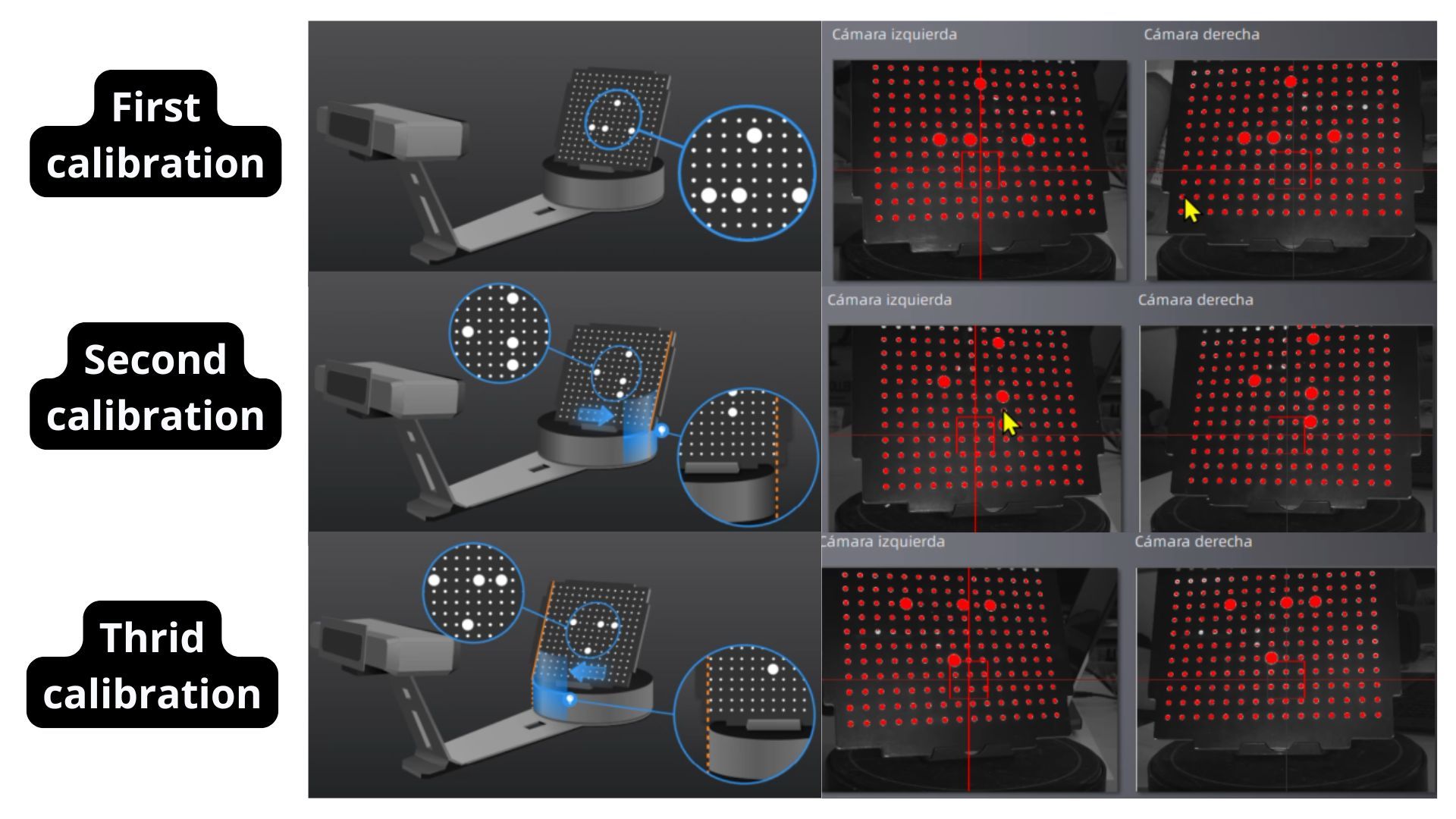
Initial calibration tests.
The second calibration test is performed using a white office sheet in the same manner.
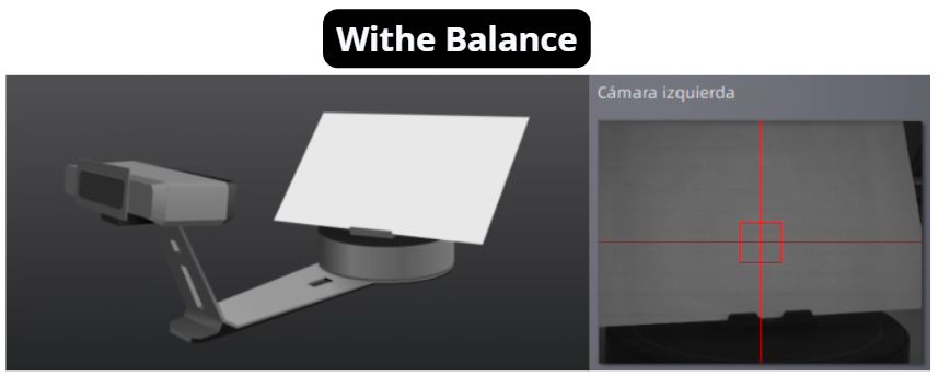
Second calibration test.
Scanning Process
Scanning Steps
- Place the object on the scanner base.
- Configure scanning parameters in the left panel; be careful with the brightness setting.
- Start the first scan.
- Once finished, click the stop symbol in the right panel.
- Rotate the model on the base to scan the rest of the piece.
- Repeat the process until most of the object is scanned.
Note: In the first scan, I set 30 "platform steps," which took about 15 minutes. I recommend setting this parameter between 12 and 15 steps.
Deleting Imperfections
- To delete imperfections, hold Shift and select the errors.
- Click the "Selected Elements" button.
- Click the last button on the right panel to finalize the scan.
Importing the Scan
- Click on "Watertight Model" to automatically fill holes. Usually, it works well; otherwise, this option can be undone.
- Preferably, click "Medium Detail," as it looks great and higher detail takes much longer.
- Click "Export" and choose the format; I recommend STL and OBJ.
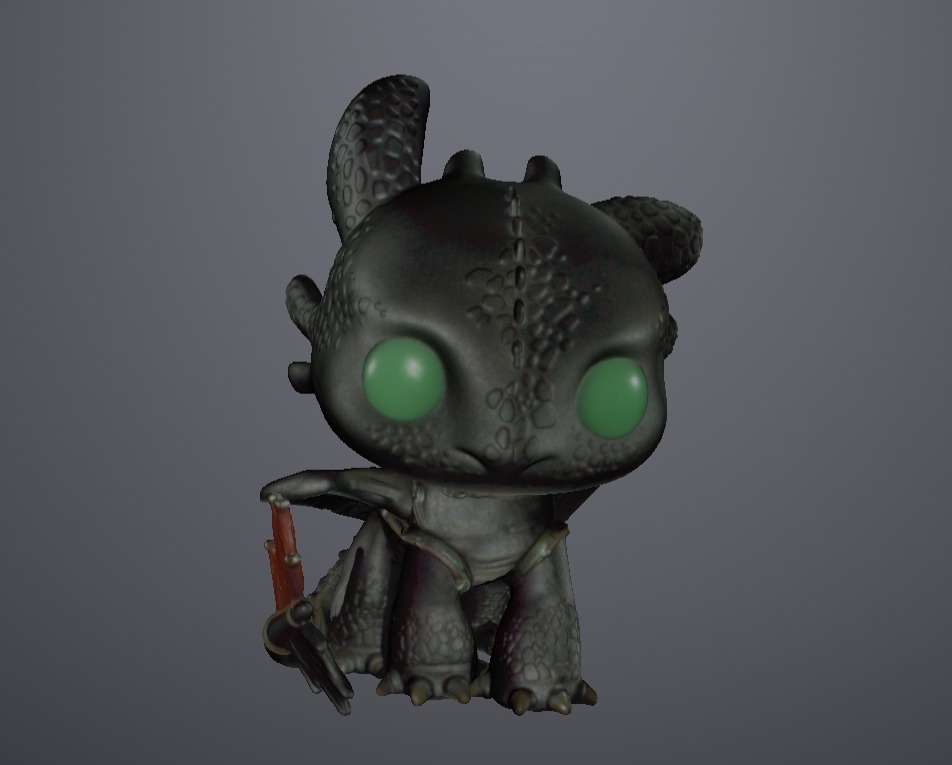
Below is a video showing all the steps performed for the scan.
Result
Height Comparison
I had the opportunity to print the piece with original parameters, without modifications, to see the size difference.
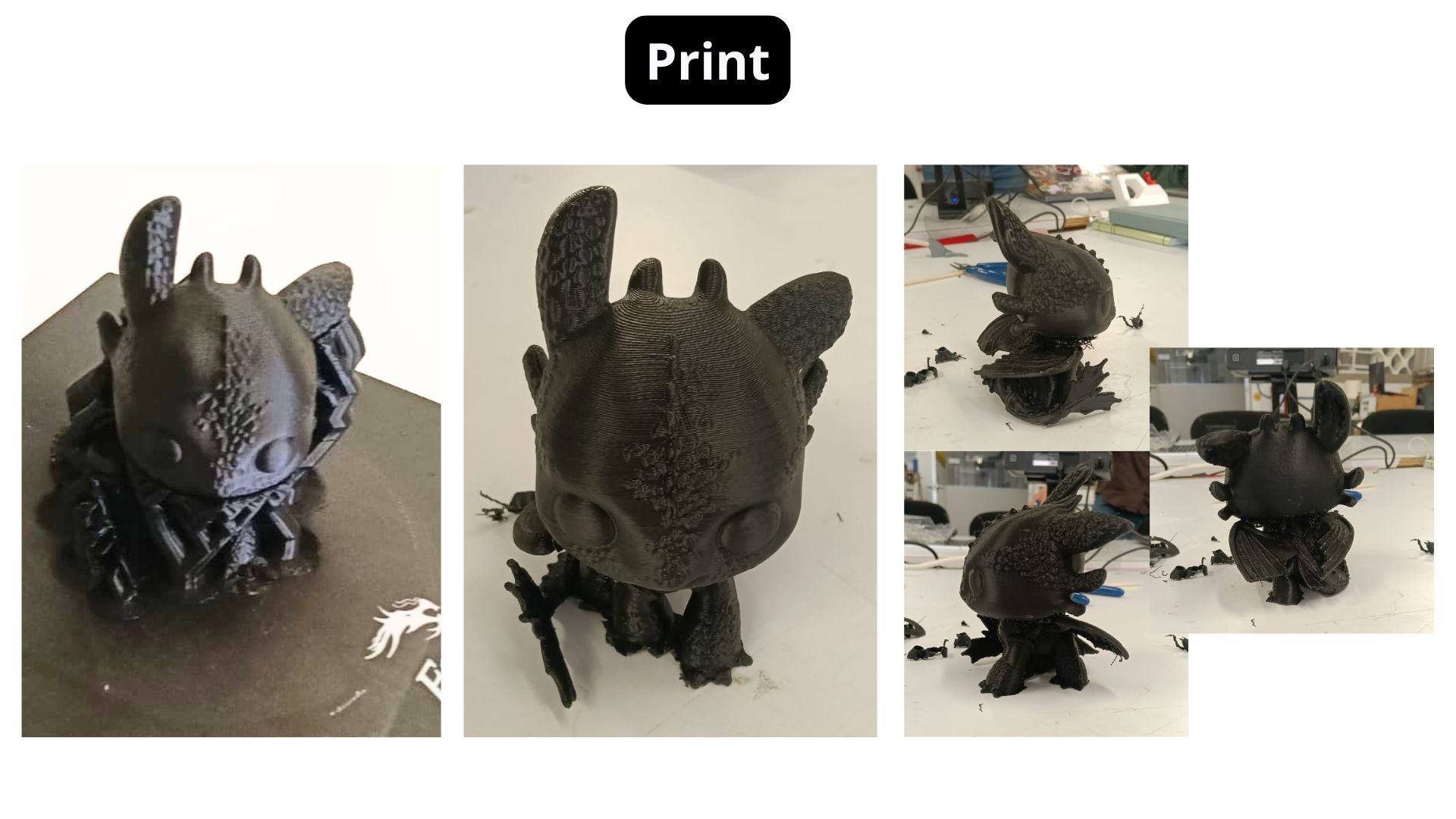
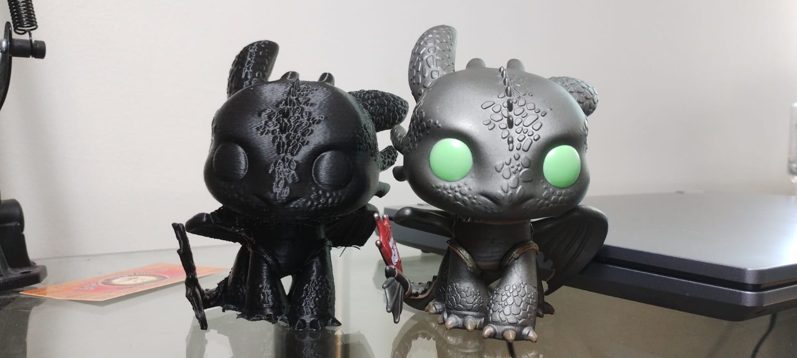
Size difference between the real model and the print.
3D Printing — My Piece Design
Justification
The piece I designed in SolidWorks is an assembly made of the different shapes found in poker cards. I always wanted to design my own earrings. Additionally, I had the chance to use different filaments on the Prusa printer, something I also wanted to try.
I believe my piece cannot be made by any method other than 3D printing without having to make separate parts and then creating openings to assemble them.
SolidWorks Process
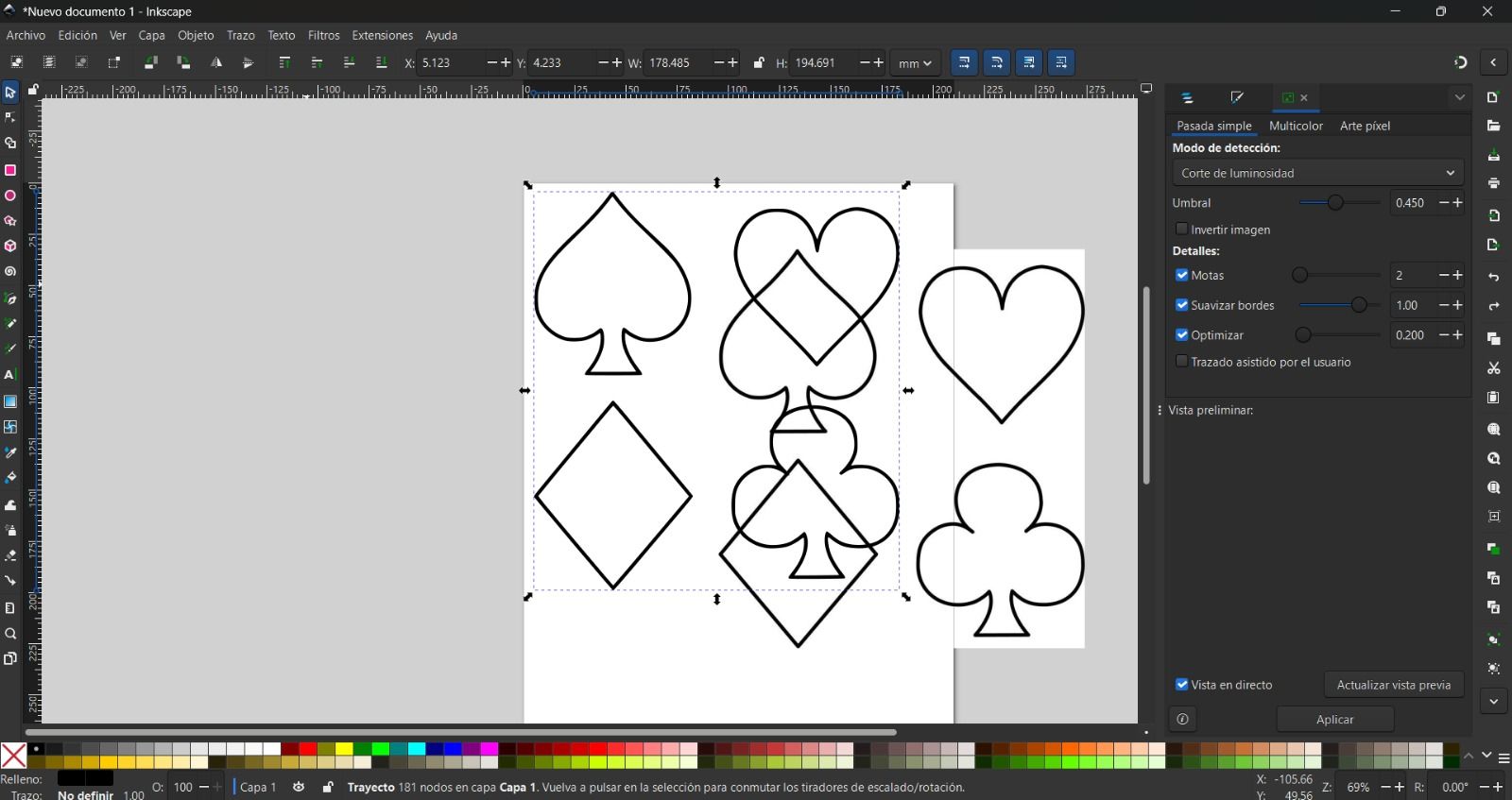
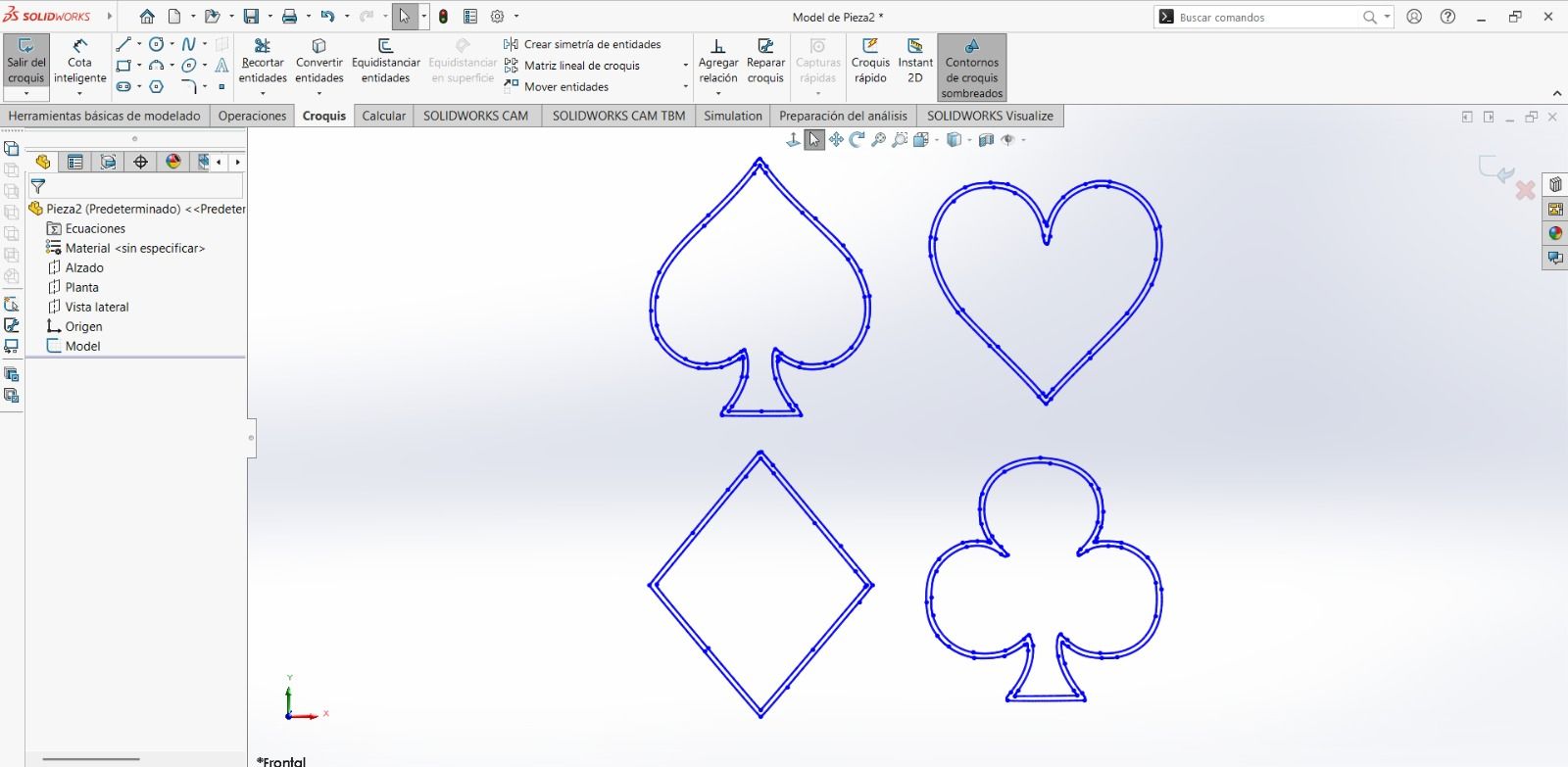
I started by looking for an image of the pieces on Pinterest to convert it into a vector in Inkscape and later export it as a DXF to open it in SolidWorks.
In SolidWorks, we select "Open," choose the DXF option, and follow the import settings. Once finished, click "Next." To see how I imported a DXF for modification, here is the YouTube video I learned from.
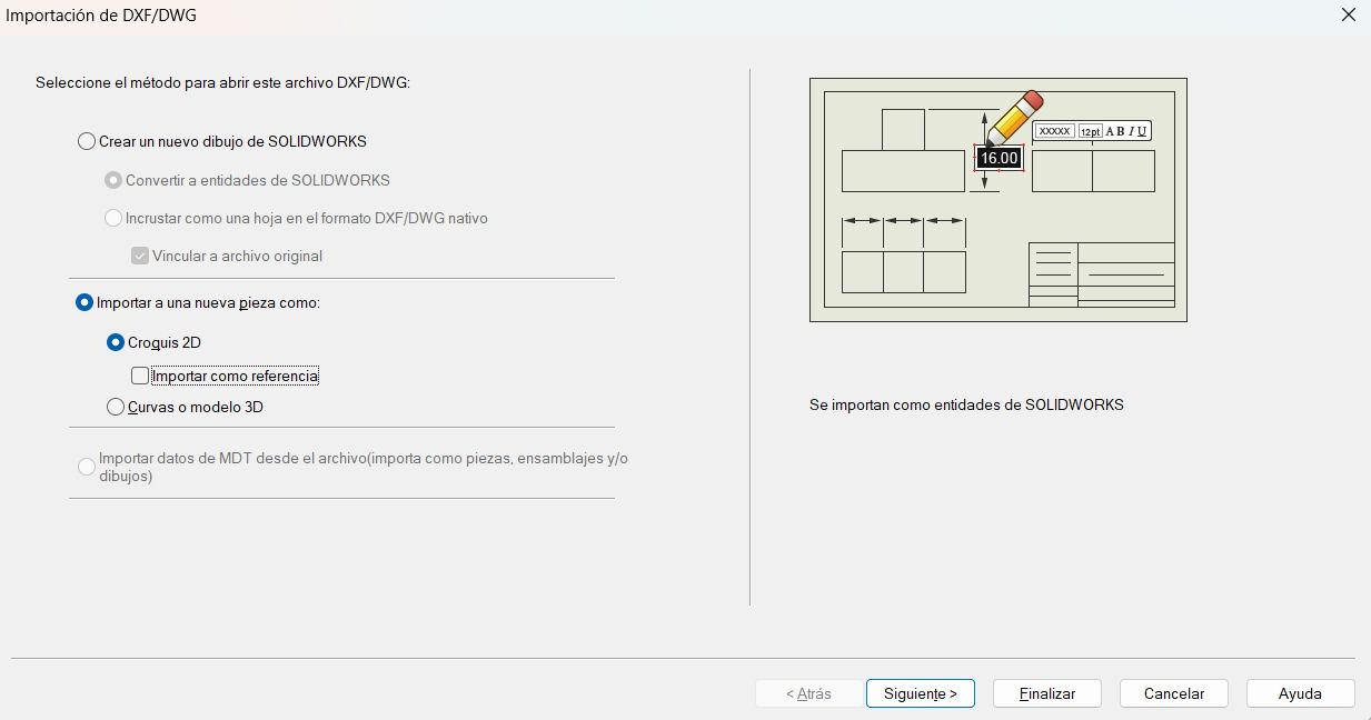
DXF import options in SolidWorks
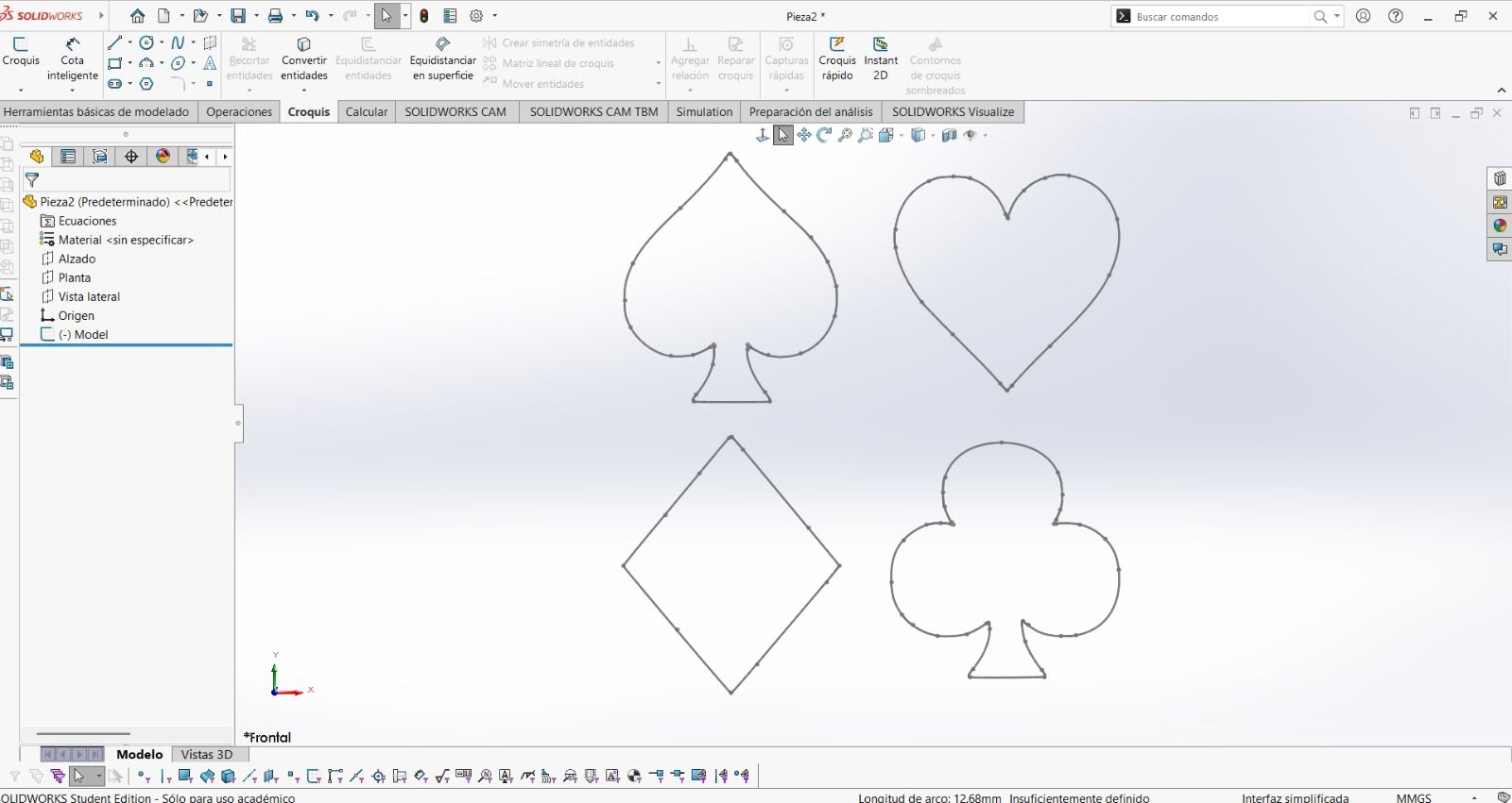
It will show a preview where we set the working units. The dimensions appear, but since I only need one set of outlines, I delete the internal chains of each figure.
Using the "Swept Boss/Base" operation, I decided on a 3mm diameter so the earrings wouldn't be too thick. However, after printing, they were too small because I scaled the piece in Prusa Slicer. Therefore, the final thickness I used in SolidWorks was 10mm.
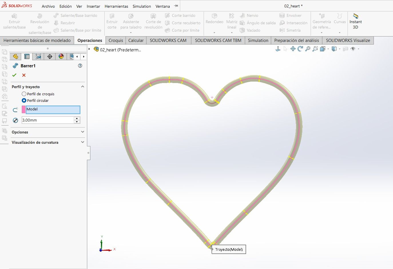
"Swept Boss/Base" operation in SolidWorks
Care must be taken, as I had to round the corners of some pieces more because the "Swept Boss/Base" operation showed an error.
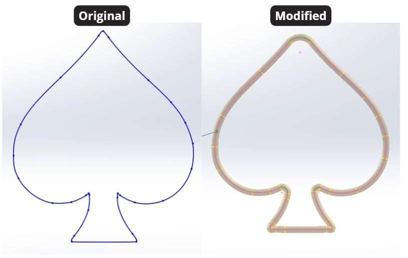
Piece requiring corner correction
This is how the assembly ended up. Note that the top piece is the one I designed to hold the entire assembly, where the hook for the earrings will be attached.
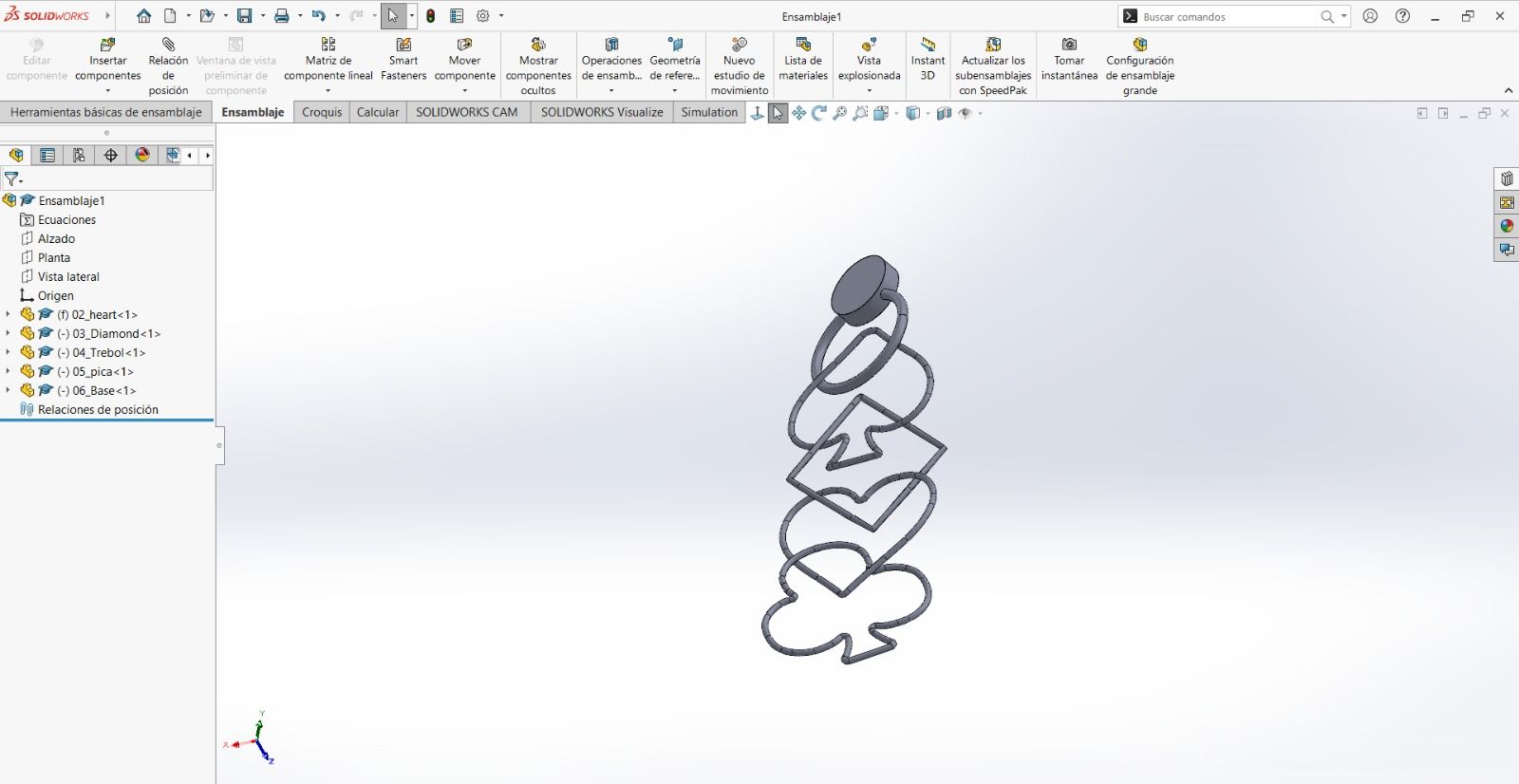
Finished assembly in SolidWorks
Note
It is important to arrange the assembly pieces horizontally to avoid support issues.
Software: Prusa Slicer
Note: In the top right corner, it is important to enable "Expert Mode" to see all design options.
In Prusa Slicer, I first scaled my document since it was too large for earrings.
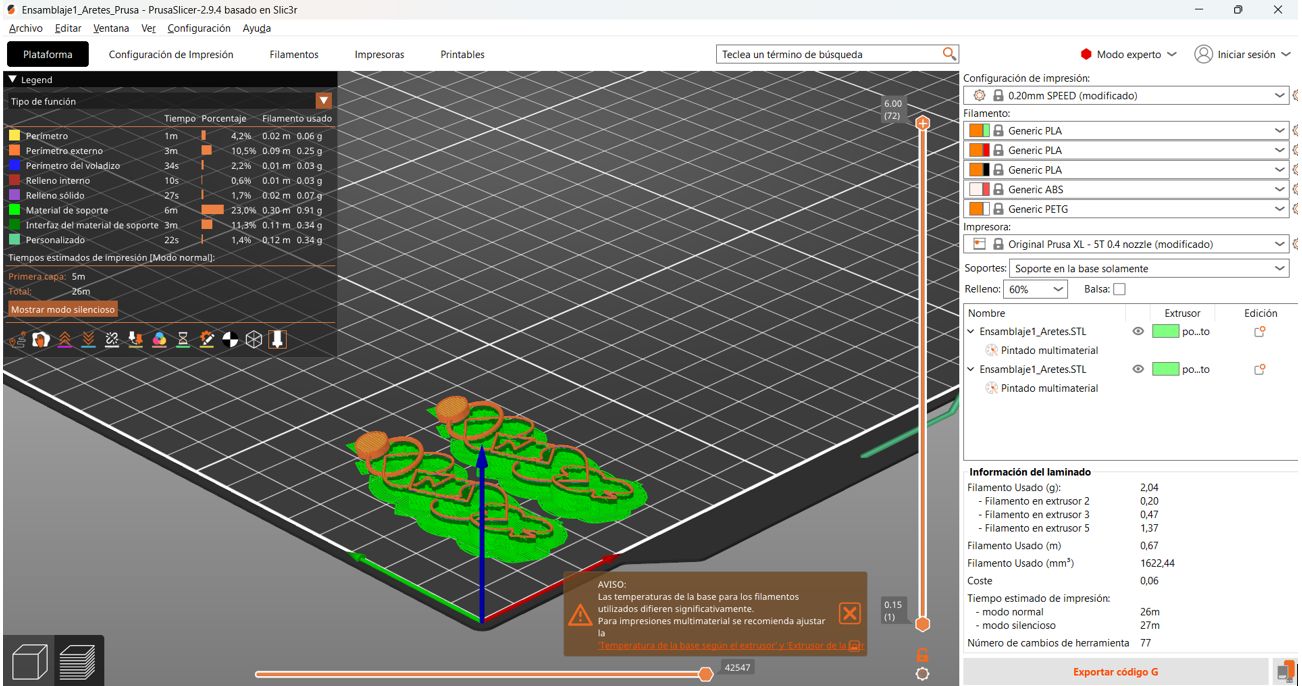
Scaled pieces in Slicer.
Color Assignment by Extruder
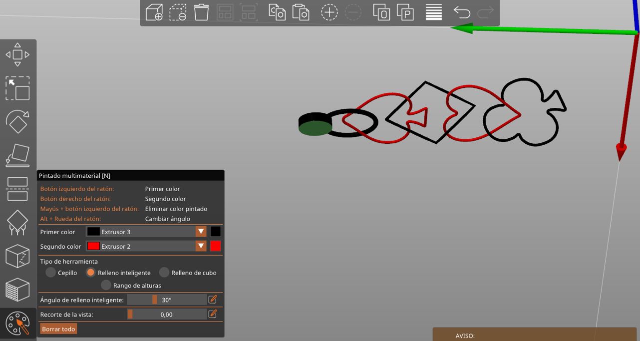
To follow the poker card aesthetic, I decided on red and black pieces. In the main left panel, there is a palette icon used to assign colors to each part of the print.
- Left click on a part to assign Extruder 1 (Black).
- Right click on a part to assign Extruder 2 (Red).
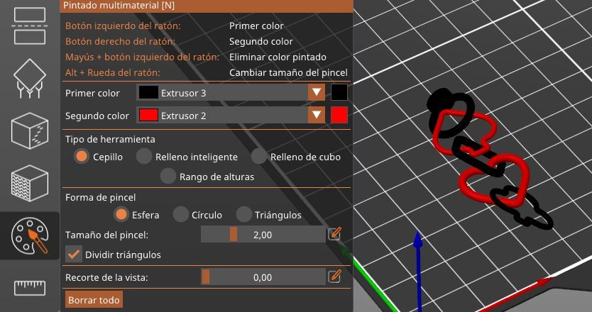
Color assignment by extruder
Next, change the filament types in the right panel and scale the file to 60mm on the "Y" axis in the "Object Manipulation" section.
First click Slice now and then Export G-code.

Slicing process and G-code export
Note: Be careful to change the bottom parts.
Printing Tests
With the original print where all pieces were 3mm wide, the print failed. The second photo shows the second attempt where some pieces had a 10mm thickness before scaling. Unfortunately, not all shapes allowed the same thickness (ranging from 7mm to 10mm).
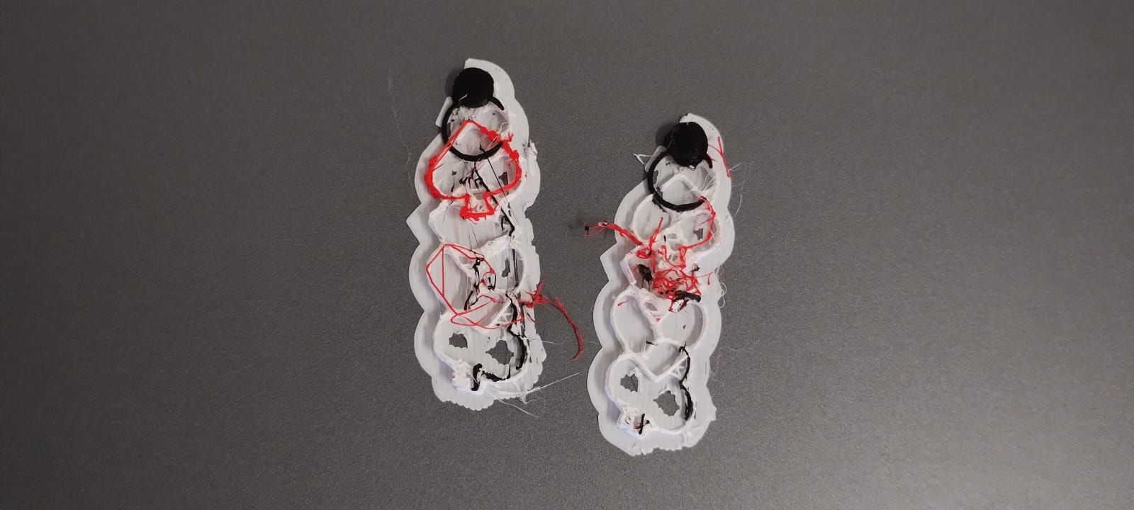
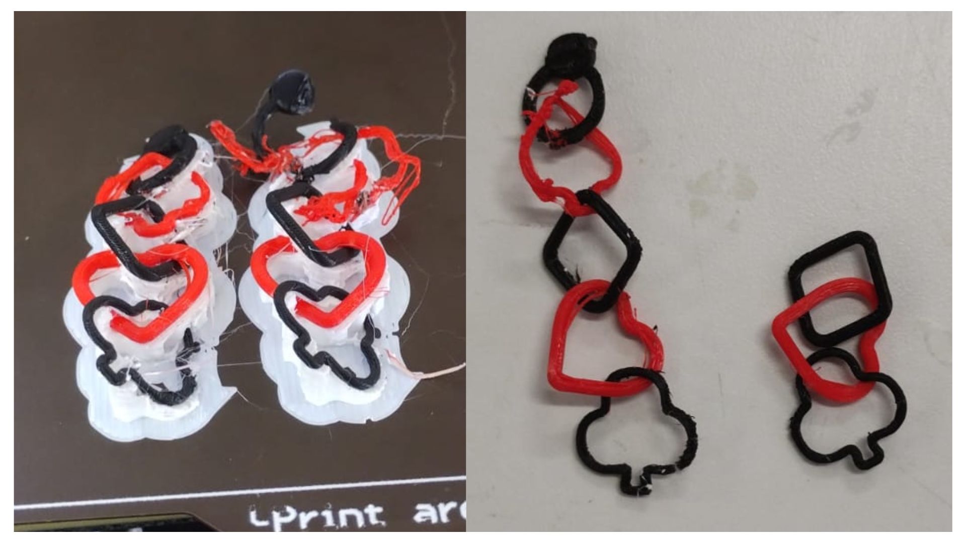
Note: Due to recent events in Puebla, I couldn't return to the university to reprint with greater thickness. However, those files are in the "Files" section.
Resin Printing
Software: Anycubic
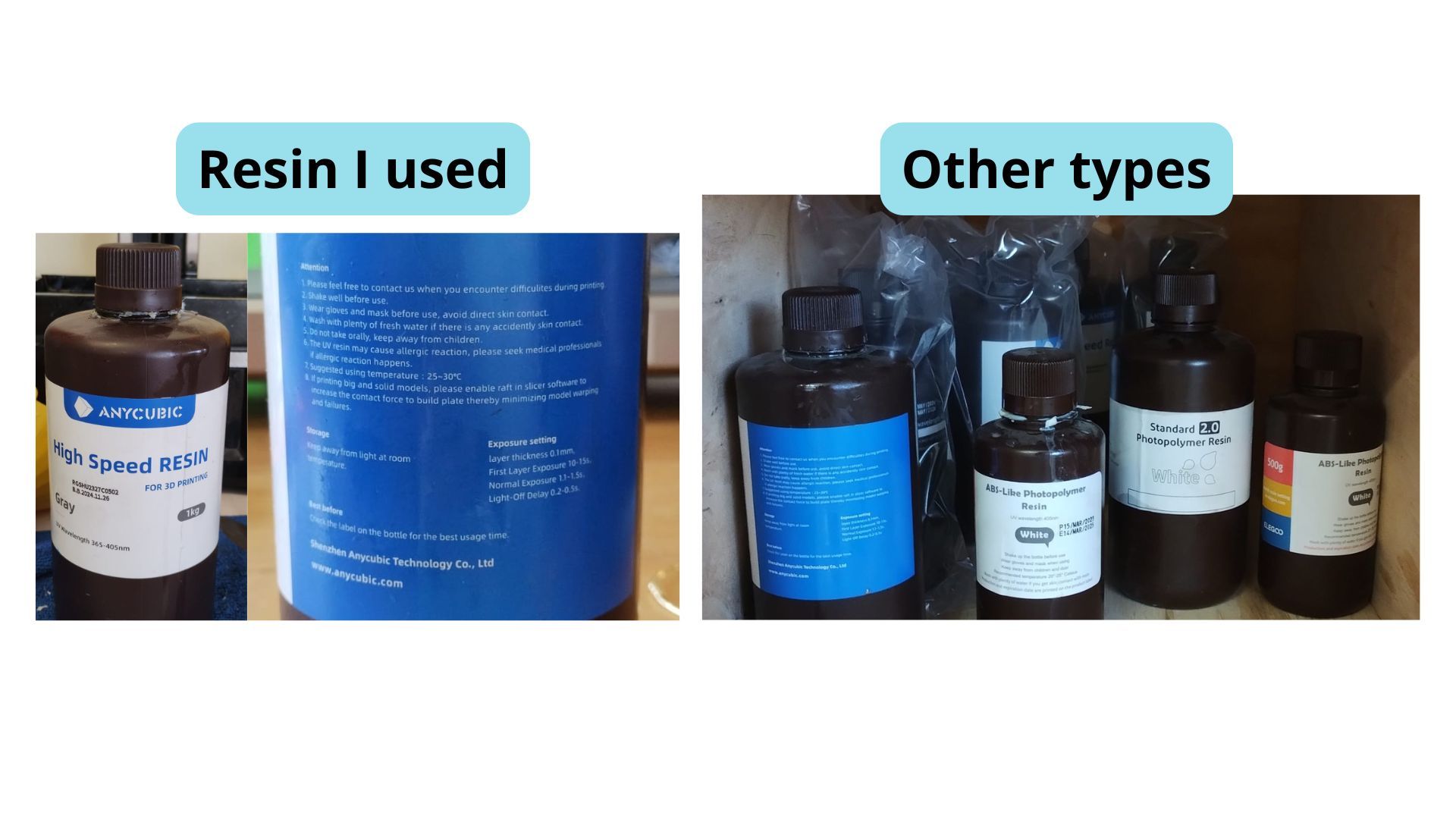
I used fast resin, but there are other resins available in the lab as shown in the image.
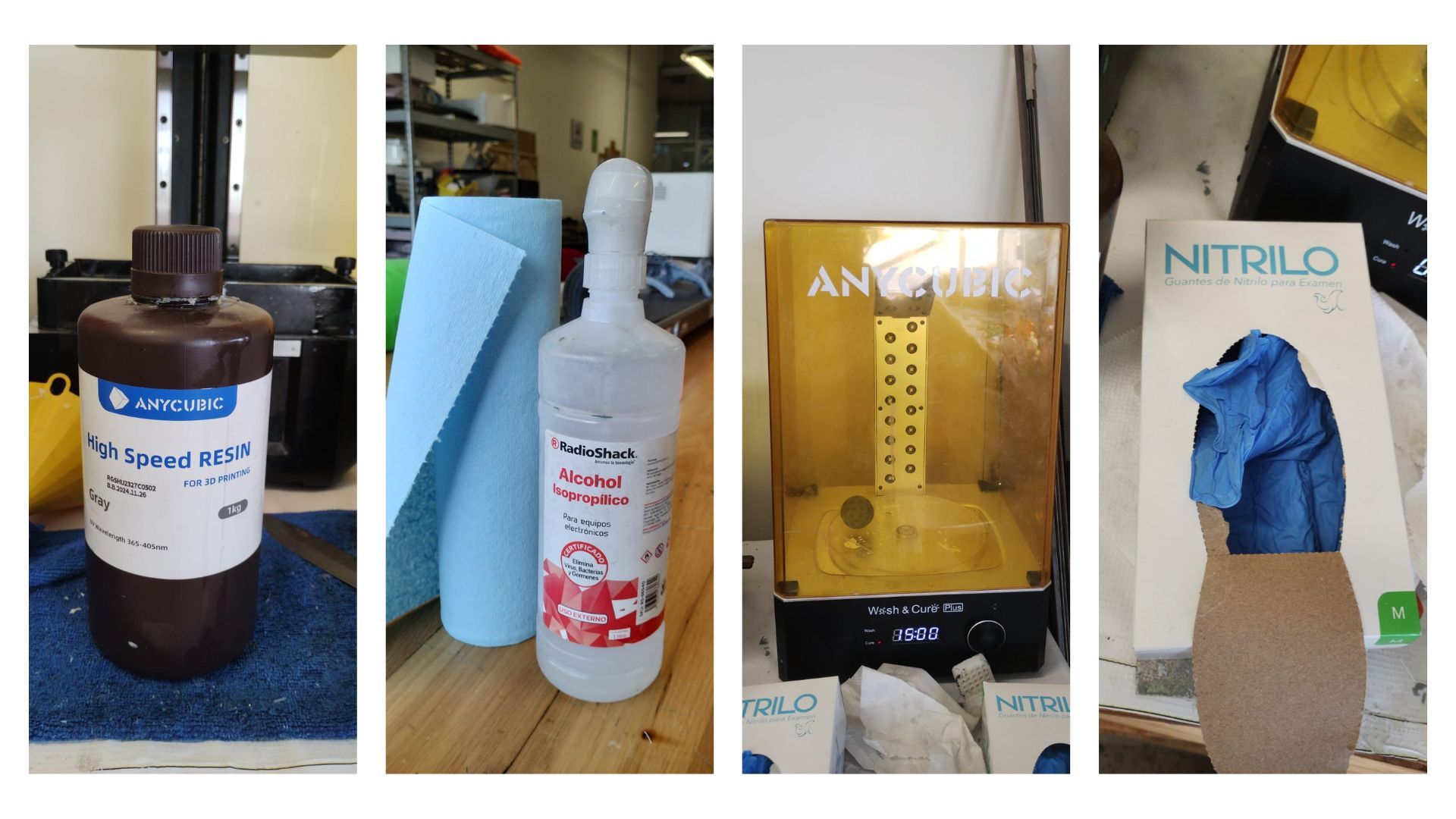
Required Materials
- Resin
- Isopropyl Alcohol
- Blue towels
- Curing machine
- Nitrile gloves
Critical Parameters
| Parameter | Description |
|---|---|
| Normal exposure time | Time the light stays on per layer. (2.3 seconds) |
| Off time | Time the light is off. |
| Bottom exposure time | Ensures adhesion to the build plate. |
| Infill structure | If hollow, at least two holes are needed to drain resin. |
Instructor Recommendations:
- If a large flat area is attached, tilt it at a 45° angle in Anycubic software.
- Always include at least one drain hole in non-solid parts.
- Use compressed air to force resin out if the infill obstructs drainage.
Post-processing
- Wash with isopropyl alcohol and dry with blue towels.
- Cure the pieces in the curing machine; in my case, for 15 minutes.
- If they are still not dry, leave them in the sun.
Parameters I Used
Unfortunately, I couldn't complete the prints as they failed. However, to achieve the expected result, I would:
- Tilt my pieces.
- Add more drain holes.
- Bottom exposure time: 30 seconds.
- Infill structure: Hollow.
Software parameters
Extra Tools
| Tool | Description |
|---|---|
| Rodin | Software that allows auto-generating 3D models from a picture. |
| Maker World by Bambu Lab | A collaborative space for digital fabrication where ideas transform into prototypes through "learning by doing." |
What I learned this week:
- I learned how to use the EinScan SE scanner, including calibration with the calibration plate, removing imperfections using the Shift key, and exporting the final model in STL and OBJ formats.
- I learned how to import DXF files from SolidWorks into Prusa Slicer, assign colors to different extruders, and export G-code for multi-color printing, although I discovered the minimum thickness (3mm) was too small and had to redesign at 10mm.
- I understood the critical parameters of resin printing: exposure time, off time, and infill structure, as well as the importance of including drainage holes and tilting parts at 45° to avoid failures.
What I learned from the group page:
- I learned about the main 3D printing technologies (FDM, MSLA resin, SLS, etc.) and the technical specifications of each printer available in the lab, including build volumes and resolutions.
- I understood the design rules for FDM: the maximum overhang angle without support is 45°, minimum wall thickness is 2–3× the nozzle diameter, and the part is mechanically weakest along the Z-axis.
- I learned about different infill patterns (Grid, Triangles, Cubic, Concentric, Zig-Zag, etc.) and when to use each based on the required strength level: low stress (15–50%) or functional (>50%).
Files I used this week
3D Printing_Files.zip
3D Files
The following files are included in the package:
- 3D Model: Ensamblaje1_Aretes_Prusa.3mf
- G-code: final_earrings_to_print.bgcode