System Integration
Project Goals
This project involves multiple systems that can be added or discarded, depending on the time available for me to complete my final project. This systems are listed as follow:
| Priority | Included Systems |
|---|---|
| BASE | “Robot-like” casing for a Raspberry Pi 5 with an LLM model, with user voice input and Text to Speech output. |
| 1 | Added a rotating base that moves to the general direction of the user voice. |
| 2 | Added a person recognition module (Xiao Sense) to track the user position and adjust the rotating base as needed. |
| 3 | Added servo motors on the base of the articulated tentacles to enable the “tentacle movement” play feature. |
| 4 | Added a capacitive sensor in the head of the robot to enable the “petting” play feature. |
This goals work as a pyramid, where the base of the pyramid is the BASE tier and the top is the “3” tier. If time becomes a problem during the development of the project, the included systems will be removed from top to bottom.
Task Manager
For this project I created a google sheets document to track my pending tasks. This tasks manager will be including time stamps of the initialization and ending of a task. In the near future, the ending of each task will be scheduled.
User Diagram
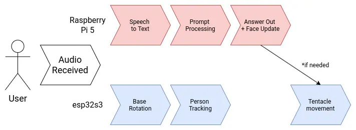
Brain Diagram
My project involves two main brain requirements. The first one being the LLM processing aspect. This part will take care of “hosting the AI”, plus anything involved with its functioning, like the speech to text and text to speech services. The second one being the peripherals control. This being any input and output devices included in the project, like the microphone array and the tentacle movement. Having a single micro-controller or single board computer to do all of this is not optimal. In the spirit of “dividing and conquering”, I decided to separate both systems into a “muscle and brain” configuration.
The “brain” of the robot will be a Raspberry Pi 5. Raspberry Pi 5 are small and powerful single board computers, already used for AI applications like hosting local LLMs. The Raspberry Pi 5 by itself can perfectly run all of my AI related services by itself. The “muscle” of the robot will be an esp32s3. This is a fast and versatile micro-controller powerful enough to handle any input and output device we attach to it. Both the muscle and brain need to be connected to one another to coordinate. Specially for sending activation signals from the brain to the muscle. For this, an UART connection will suffice. If a more complex communication necessity presents during the development process of the robot, both offer WiFi connectivity, opening the possibility for an HTTP connection as well.
Power Supply
There are multiple voltage requirements for the different systems present in our robot:
- The stepper-motor controller will need a 12v supply.
- The Raspberry Pi 5, esp32s3 and Xiao Sense will need a 5v supply.
- Servo motors work best at 6v. (SCRAPPED)
- The MEMS microphone modules will need a 3.3v supply.
Working with multiple voltage requirements is usually not a big deal. Many electronics, like laptops for example, have a base voltage input (usually the larges most used voltage) and then it´s transformed accordingly. Using a buck converter for the 5V and 6V line, our voltage problems will be solved:
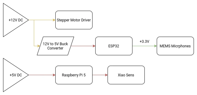
Our main +12V DC power source will be an external 12V 5A power supply. 5A should be enough for our consumption requirements, although bumping it up to 10A might be necessary. I’m not an expert and can’t really do the needed calculations to get my max amperage value. If I get to that value (with help of my instructors), and it’s greater than 5A, I will be changing the power supply.
At the time of updating this, the one concern I have is with my slip ring. The slip ring I ordered comes with pretty thin cables. This is why I ordered one with 8 cables, with the intention of using multiple cables for a single power line in order to protect those cables. For the 4 lines I will be needing (Ground and 3 +12V lines), it leaves me with 2 cables per line, that should be enough to sustain the power going through them. If two cables per line is not enough, there is a 12 cable option I could get.
Note: As of May 3th, the slip ring is no longer considered.
360 Rotating Base
The main aspect of the final project is it’s ability to rotate 360 degrees, enabling the sound detection -> person tracking functionalities of the robo-agent. For this rotary base to work properly, we need a couple of components:
- A stepper motor.
- An electrical slip ring. (SCRAPPED)
- A 3D printed base with a gear system.
For this rotating base, a gear based system seems optimal, as to allow a single motor to deliver the torque needed to move the whole robot. As I don’t currently know the weight of the final robot, the gear based system needs to have enough torque to move it, plus having the precision to face the robot to an exact angle. For torque and precision applications, a planetary gear arrangement is optimal.
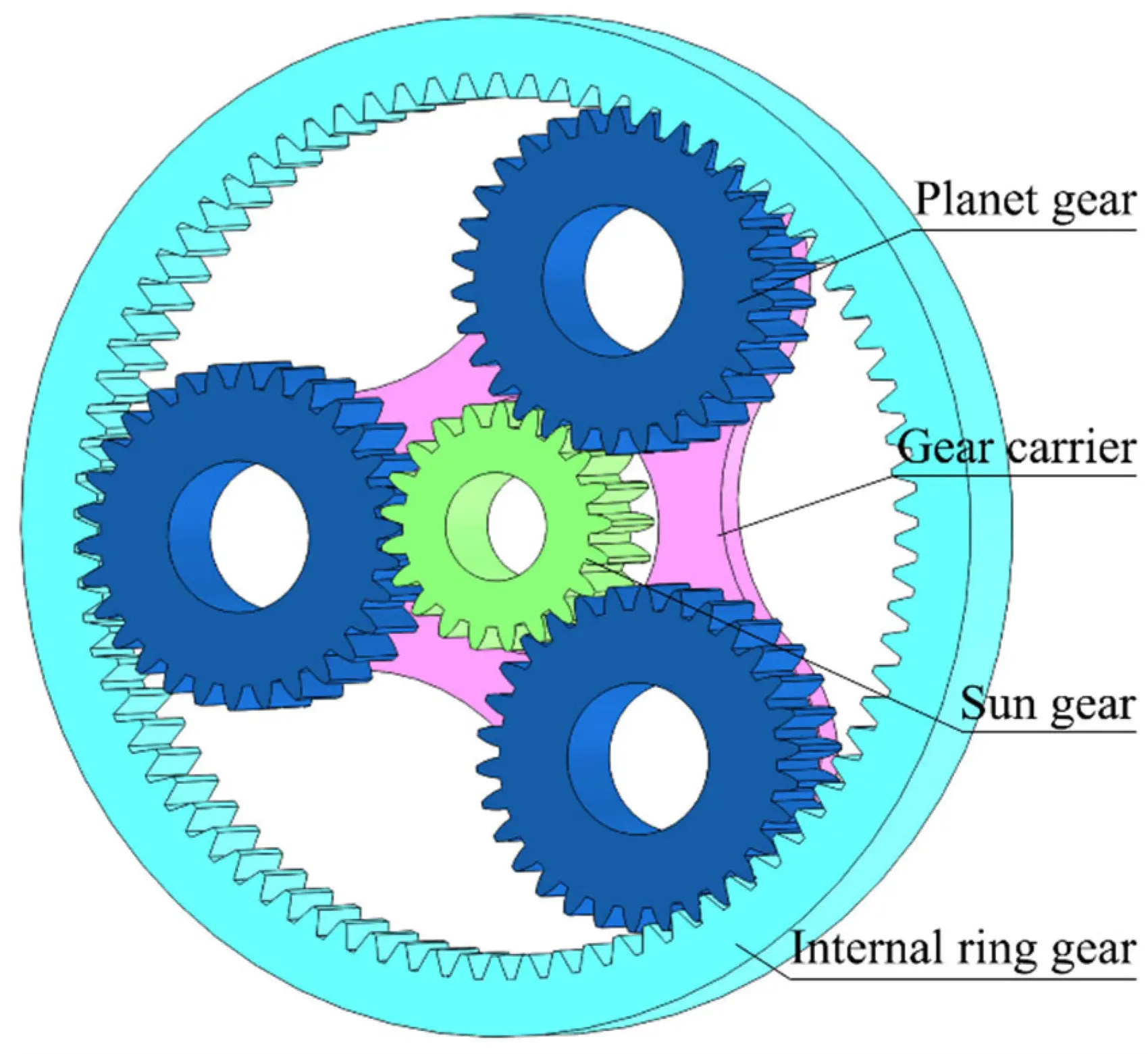
For a better explanation on how planetary gears work, and how to make them, check out this YouTube video by the 3D Printer Academy channel. The idea is to design a similar planetary gear from scratch, with a 5:1 movement ratio (standard for robotics applications). A NEMA stepper motor will be placed underneath the sun gear for the base movement. Plus, ball bearings are proposed for the inside of each planet gear, for a smoother rotation of the gear carrier. The base where the robot will be placed will also be attached to the top of the gear carrier.
Getting more into electronics, the stepper motor will be wired into a drv8825 driver, which will then be controlled by the ESP32. This driver is more than enough to allow for my motor to work. In the programming department, the stepper motor can use a similar script to the one I developed for my week 14 assignment, with a few modifications, including adding the UDP communication logic, the sound detection and the 5:1 ratio implementation.
The ESP32
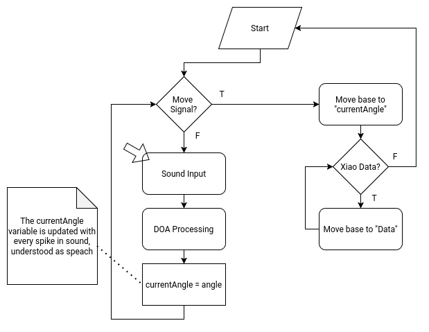
The ESP32 will manage the rotating base movement and the INMP441 MEMS microphone array for the sound detection system. For this, the ESP32 will require the following functions on its script:
- A “Home” function in the setup of the script, to return the robot to its home position. The robot will slowly spin into one direction until receiving a signal from the a3144 hall sensor on the base of the robot.
- A DOA (Direction of Arrival) algorithm That will constantly detect the direction of the incoming sound. This DOA algorithm will be the “idle” state of the micro-controller. This algorithm requires the following considerations:
- It needs to translate the incoming data of the MEMS microphone array into an angle.
- It needs a filter to prevent ambient sound from being processed.
- When a peak of sound is detected, understanding it as a voice detection, the calculated angle needs to be saved into a local variable.
- When receiving the activation signal from the Raspberry Pi 5 (trough UDP), a first movement function should activate, moving to the saved angle.
- When receiving data from the Xiao Sense (trough ESP-Now), a second movement function should activate, adjusting the position to match the data received. When data is no longer received from the Xiao Sense, the micro-controller should return to the idle state.
The Xiao Sense
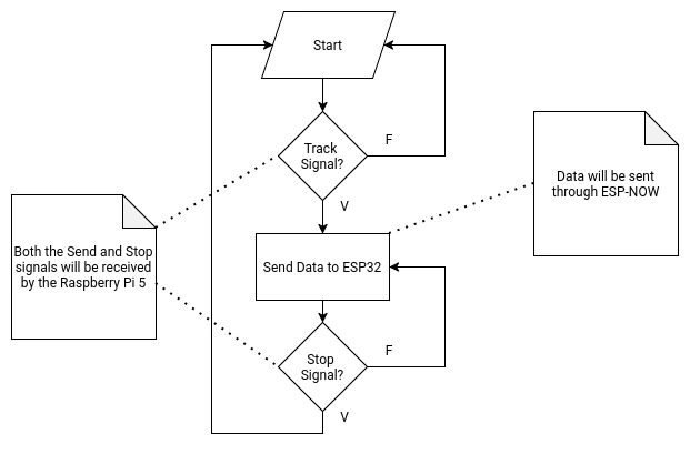
The Xiao Sense will manage the person tracking system of the robot. The Xiao Sense needs a person detection vision model. This model can be directly downloaded from the Seeed Studio page, allowing for implementations on Platformio or Arduino. For Arduino, the Seeed Arduino SSCMA library is also suggested. The Xiao Sense will also requiere the following functions on its script:
- Implementation of the vision model into the script.
- A first person detected lock that prevents more than one bounding box from being created.
- A function that calculates the aproxímate position of the person on the X axis.
- Data sending function to the ESP32 (via ESP-Now). The Xiao will send the calculated position value to the ESP32 until receiving the “stop” signal.
- Data receiving function from the Raspberry Pi 5 (via UART). When receiving the “stop” signal from the Raspberry Pi 5, the Xiao Sense will stop sending data into the ESP32.
The Raspberry Pi 5
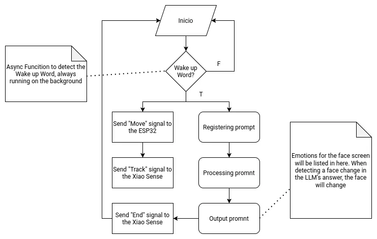
As the main brain of the robot, the Raspberry Pi 5 needs to handle two main functionalities. The first one being the LLM hosting and supporting functions. The second one being signal sending to the other micro-controllers. Both of these functionalities will be hosted on a single main file, as to allow them to coordinate and communicate with one another.
The following flow chart describes the main function:
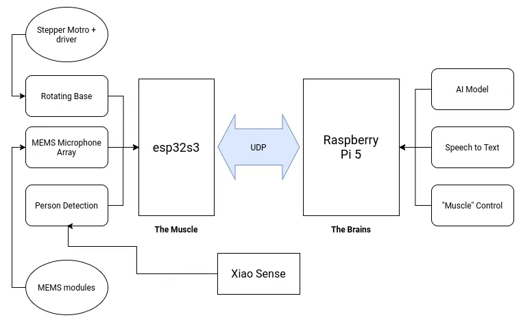
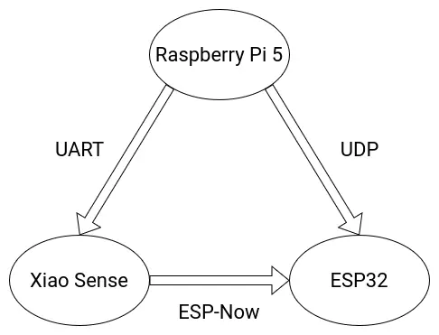
Communications
The following diagram details the final communication protocols used for the various micro-controllers involved on the Robot.
Wire Management
The Raspberry Pi 5 has integrated GPIO pins, some of which will be used to connect/power components. For simplicity sake, and to prevent the Raspberry Pi 5 from being damaged, standard “dupont” jumper wires will be used. To prevent this jumper wires from disconnecting they will be soldered to the component side of the connection. Additionally, my personal workflow involves “color coding” my jumper wires (red for power, black for gnd, etc.). For this reason, most power/gnd cables will be red and black. The rest of the cables connected to any component will be of different colors from one another, as to prevent confusion between each one.
At the time of writing this, the only components that require cables are:
- The MEMS microphone.
- The eyes screens.
- The stepper motor.
- Cables from the power supply.
The MEMS microphone and the eye screens are located inside the main casing of the robot, so using short, exact sized cables is optimal. For the stepper motor, which is located inside the rotating base, the distance from the stepper cable output and the input connection to the PCB is minimum, sol small that using a standard connection cable for stepper motor would required packing a long cable inside the base. For this reason, creating a custom connection might be optimal. The cables coming from the power supply into the main DC input block terminal in the PCB will need to be long enough to account for a possible floor positioning of the power supply unit.
Packaging
The idea of my final project is to be a “first venture” into developing an “AI powered social robot”. For this reason, a formal package is not considered as part of the development of this final project. Regardless, if a package where to be included, it would have to have an enough size to fit the whole robot as a unit. It is posible to release the main body of the robot from its rotating base, but packaging both separately would not be optimal. A single, tall and wide enough package would be ideal.