3D Printing
3D Printing is the act of taking a 3D model and, using a 3D printer, bring it to life. 3D printers use different materias that solidify in the shape of your desired object. 3D printing is an essential part of project making, as it helps makers create every piece and component they can imagine in order to bring their ideas to life. For me, this is my very first time using a 3D printer to print anything.
This is an skill I´ve always wanted to learn, and thanks to the FAB Academy I have the opportunity, material and installations to do it! First of all, we must learn a little bit of theory on how 3D printers work. For this, you can check our Lab’s Group Assignment Page. From this assignemt I learned the basic operation of 3D printers and how its components work. We also took a look at every 3D printer available at our University and how they differ from one another. I also learned the different types of materials a 3D printer can use, its aplications and considerations. Finally, I learned some important design rules for 3D prints.
The Plan
There are two types of 3D prints: Technical printing and leisure/artistic printing. Technical printing refers to prints meant to serve a purpose. This type of prints may be project casings, structures, gears, etc. On the other hand, leisure/artistic printing refers to prints meant without a defined purpose other than being a test of human creativity. Leisure/artistic prints can be sculptures, toys, articulated pieces, etc. A model being created just for fun purposes does not make it less important that a technical piece. The usage you want to give to your 3D prints is what really matters.
Here´s our game plan. We want to print 3 models:
- A testing model to test our printers capabilities.
- A technical print.
- An artistic print.
The testing model will be directly downloaded from a 3D models page like Printables Our technical print will be the tentacle we designed in week 2 with OpenSCAD. And at last, our artistic print will be created from 0 with Blender.
But Why Not Subtractively?
You might be wonder, why 3D printing? Why not creating our models with subtractive manufacturing? Subtractive manufacturing is the act of creating pieces by removing material from a base shape. Think of wood carving, where you must remove material and shape your figure by hand. There are a lot of machines, even some available on our University, that would allow us to make stronger pieces with this method.
3D printing has a lot of advantages over subtractive manufacturing. It allows for more complex shapes, like overhangs, undercuts and internal geometry. Machining pieces are not good at hollow shapes, for example. Plus, 3D printing is cheaper and faster, allowing us to create multiple iterations of the same shape until we reached the final product. Machining pieces are meant for final products only.
The reality that subtractive manufacturing and 3D printing serve two different purposes. 3D printing is best used for prototyping and more complex pieces, allowing for a vast application range. Subtractive manufacturing is best used for simple, sturdier pieces meant to be machined once and last for a long time, like gears for example.
Blender
We’ve used Blender before, for physics simulation. However, we never tackled on Blender´s main function: 3D modeling. Blender is the industry standard for 3D modeling, being used in everything from video games and movies. Its opensource nature make it the best at having a huge community and support, like plugins and tutorials. Blender will be our software of choice for artistic modeling.
Getting Started
Following our week 2´s quick Blender tutorial, we´ll create a new blank project.
Note: This next steps might not be the most optimal way of creating a model like the one I´ll choose. The method I´ll be implementing is the one I understood the most during my “Crash Course” learning phase.
For creative work, having a reference image is a good practice. For that we have to define what our very first 3D model in Blender. I decided to model a small key chain in the form of my Linux Distribution´s mascot: the OpenSUSE gecko. Why? I had no better ideas.

Importing the reference image was as easy as dragging it into the workspace.
The Mesh Method
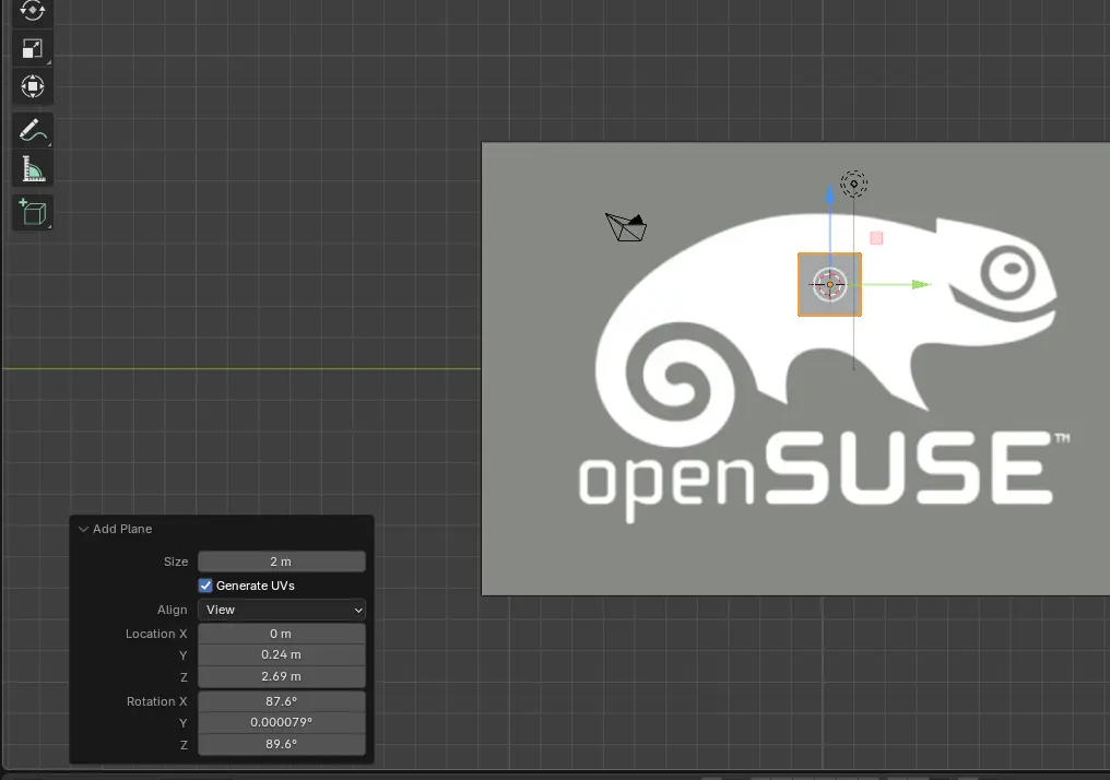
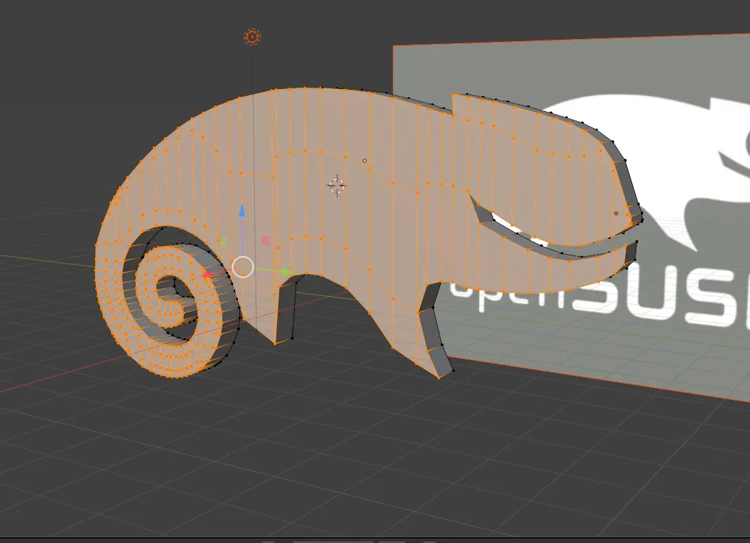
Our main strategy involved using a Plane mesh object, and modifying it accordingly to fit the shape of our object. To do this, we first need our Plane, by typing SHIFT + A and selecting Mesh > Plane. A square will appear in our workspace. A menu will appear in the left-bottom of the screen. In the “Align” drop down menu, select “View”. Now the plane is in parallel to the reference image.
Controlling the Plane is quite straight forward. In “Edit mode”, we can select our shapes corners and move them at will. This will deform our figure. Selecting to corners will form an edge, which we can extrude by pressing E.
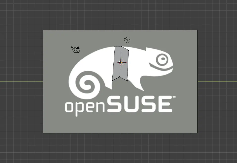
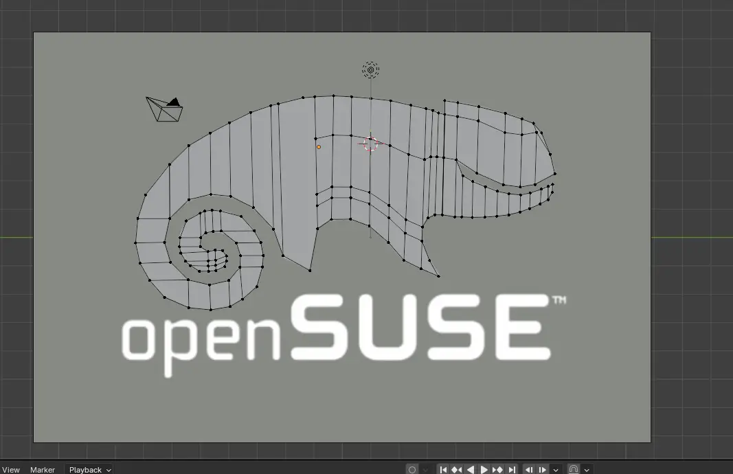
Just these two functions will are enough to cover our entire reference image. You might need to get creative with some shapes, though.
Extruding The Object and Other Modifiers
With our shape read, it is time to give it some volume. Select the whole object with the A key, and then E to extrude. Your piece will now get volume in one directions. If you wish to give it volume in the other direction for symmetry reasons, you can use a “mirror” modifier instead.
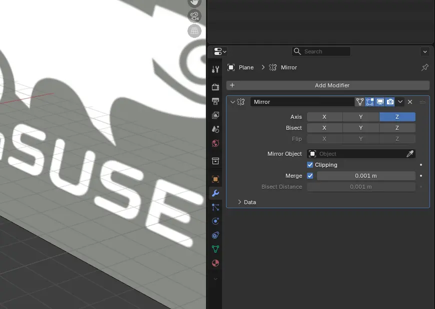
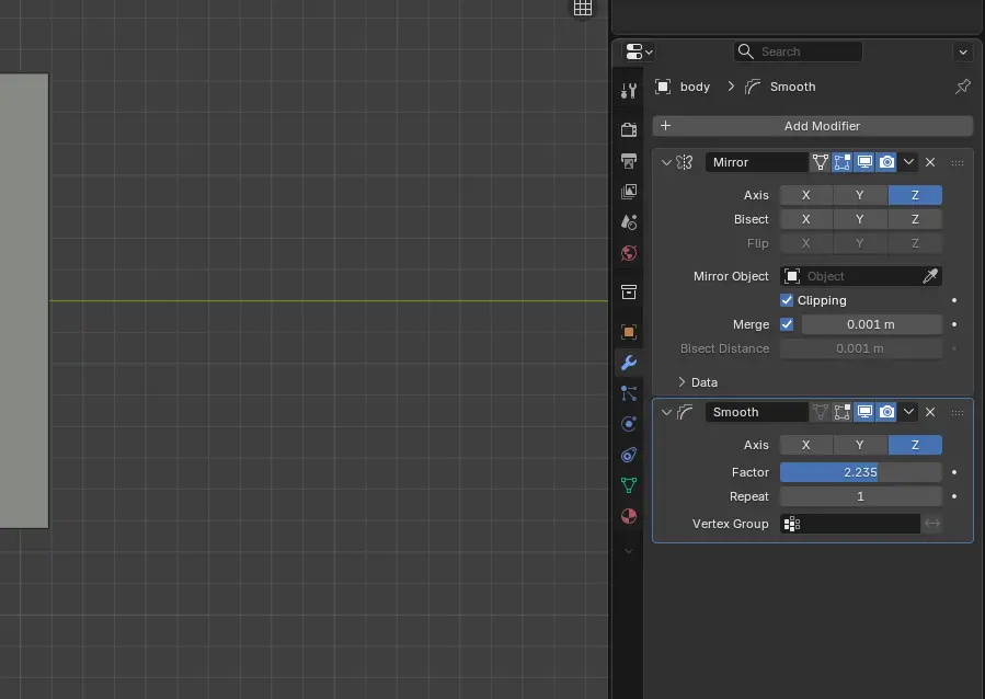
To use the mirror modifier, go to the “modifiers” menu on the right-bottom panel of your screen. It has the shape of a blue wrench. Then, select the “Add modifier” button, and type “mirror”. You can will now have a mirror modifier. For the Axis select Z, and check the “Clipping” box.
Now, we can click A and then E to extrude our figure. The figure will now extrude from both sides. Any changes made to the Editable side will be reflected on to the other side.
Another modifier we can use is the the smooth modifier, to give it a more “natural” look. To use it, we can go to the “modifiers” menu and select a “smooth” modifier.
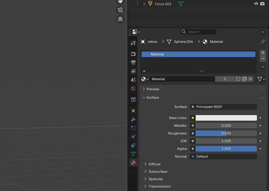
The las modification we can apply to our model is color. Color won´t be reflected in the printed version, as it´s color will depend solely on the filament color. But adding color to our render will make it look better for us. To do this, we can add a material in the “material” menu, with the shape of a red sphere. Here, we must click in “add new material”. We will now change the “Base Color” to green.
The Final Result
After adjusting the smooth modifier values, adding color and some other shapes for eyes and a key chain holder, we ended up with this final producto:
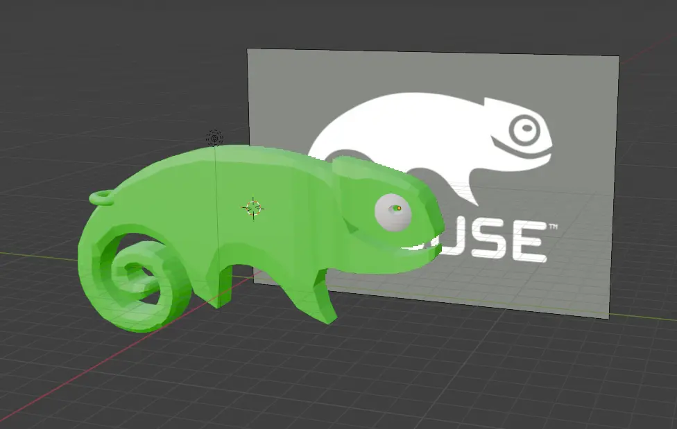
For it being my first 3D model in Blender, I was happy with the result. It is now time to remove the reference image and export the file as .stl. We can now procede with our 3D printing software to prepare the file.
Small Side Quest: Repairing a 3D Printer
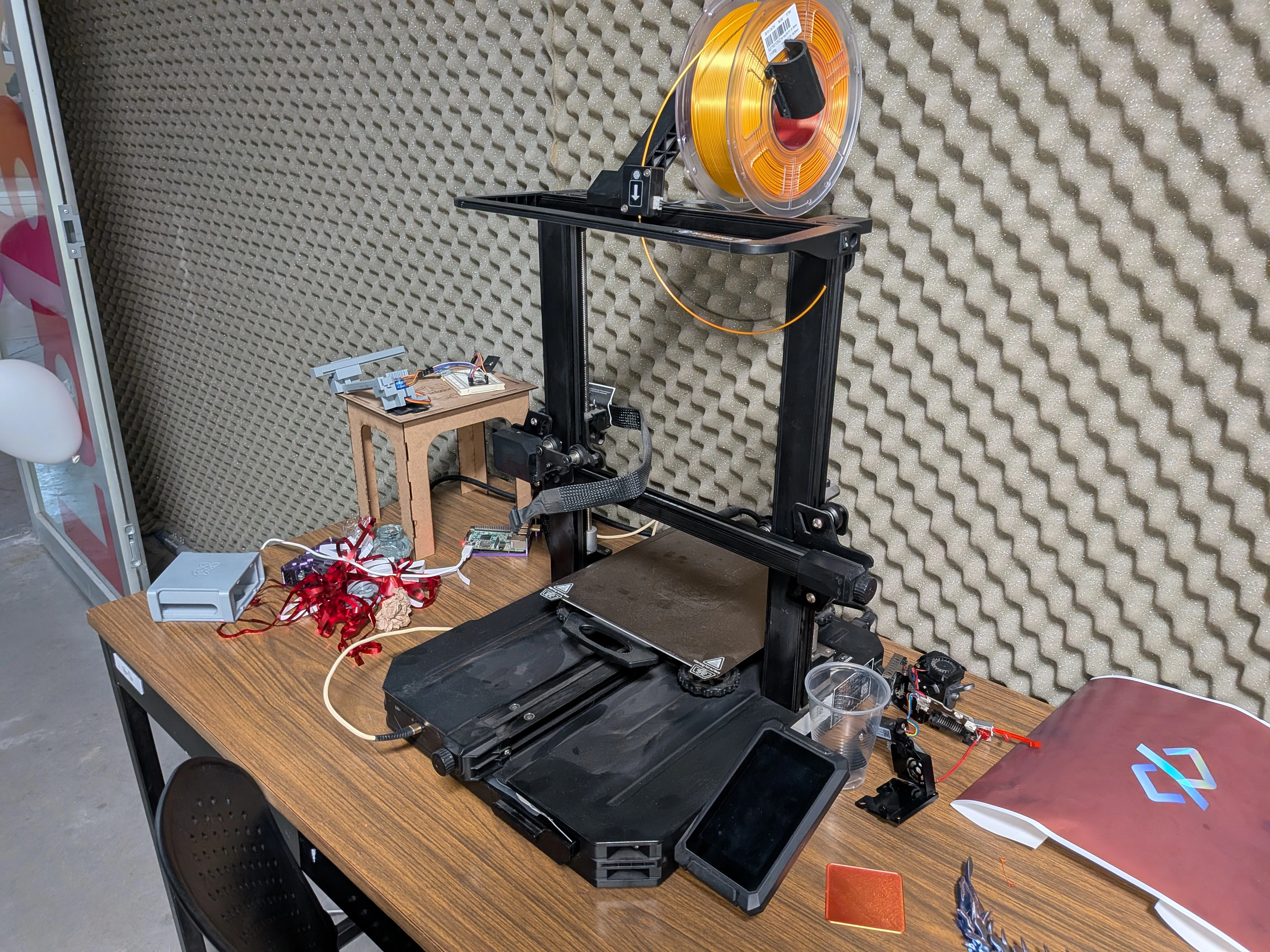
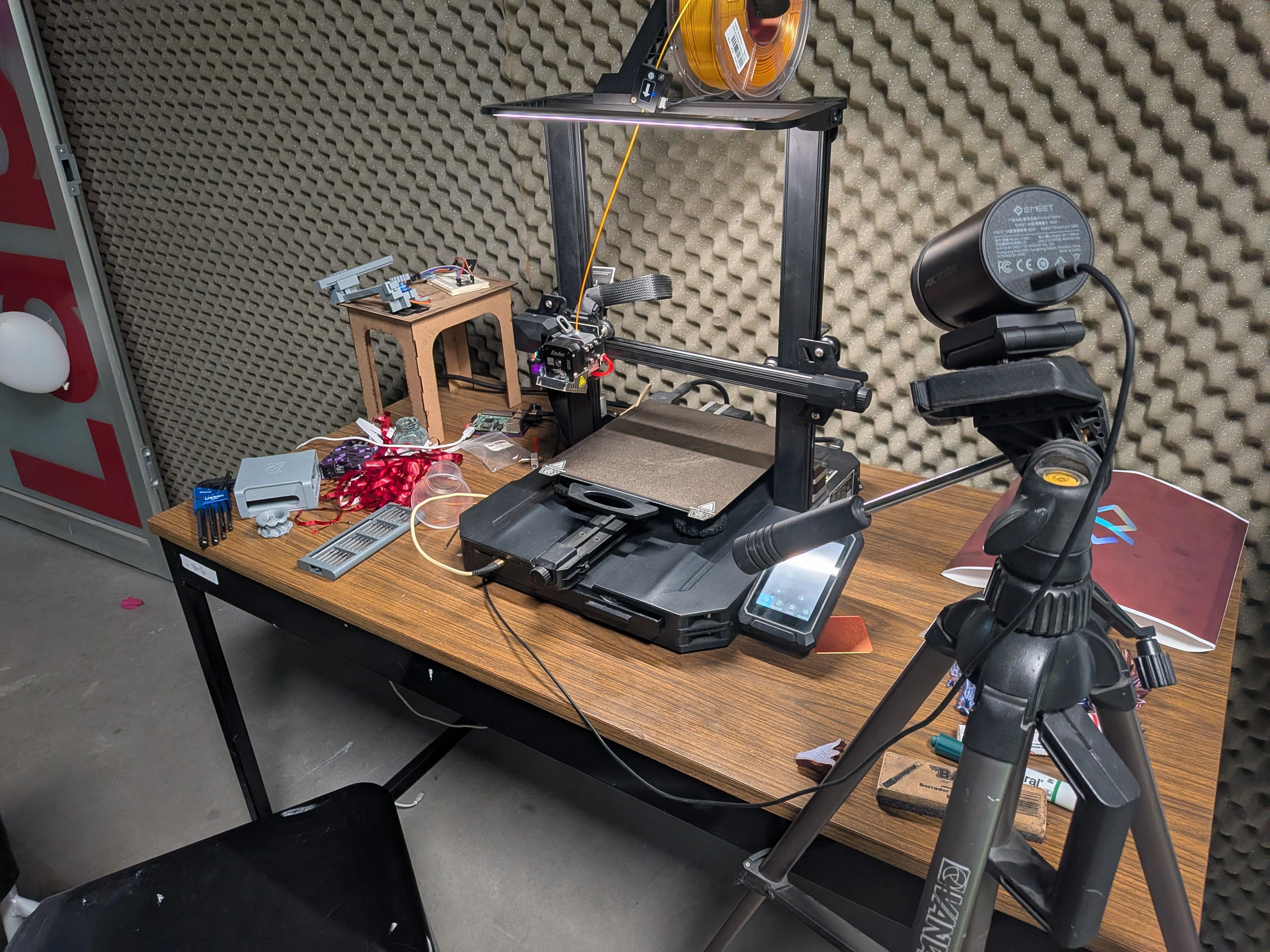
As said before, this was my very first time using a 3D printer. In our FAB Lab we have a plentiful array of 3D printers for us students to use. One of this printers is stationary in Ibero Puebla´s AI and AR Lab, formerly introduced as Professor Rafa´s Cave as it is also his office. This 3D printer is a Creality Ender 3 s1 Pro, with a small issue: It didn’t work correctly.
A little bit of 3D printer theory: In vague terms, for a 3D printer to actually print, you need a filament to be heated enough for it to become liquid, and this liquid is placed on the printing area. The melted filament then solidifies in our desired shape. The mechanisms requires two main parts: The extruder, which feed filament, and the hotend, which heats up the filament. For more information on how 3D printers work, checkout Our Lab´s group assignment.
Our 3D printer had a filament leak in the hotend. Printing with this leak would cause the print to be messed up. A quick inspection on the hotend piece revealed a mayor obstruction of petrified filament in the nozzle channel. Fixing this problem would require disassembly of the piece and removal of the obstruction, which we did.
Disassembly of the Piece
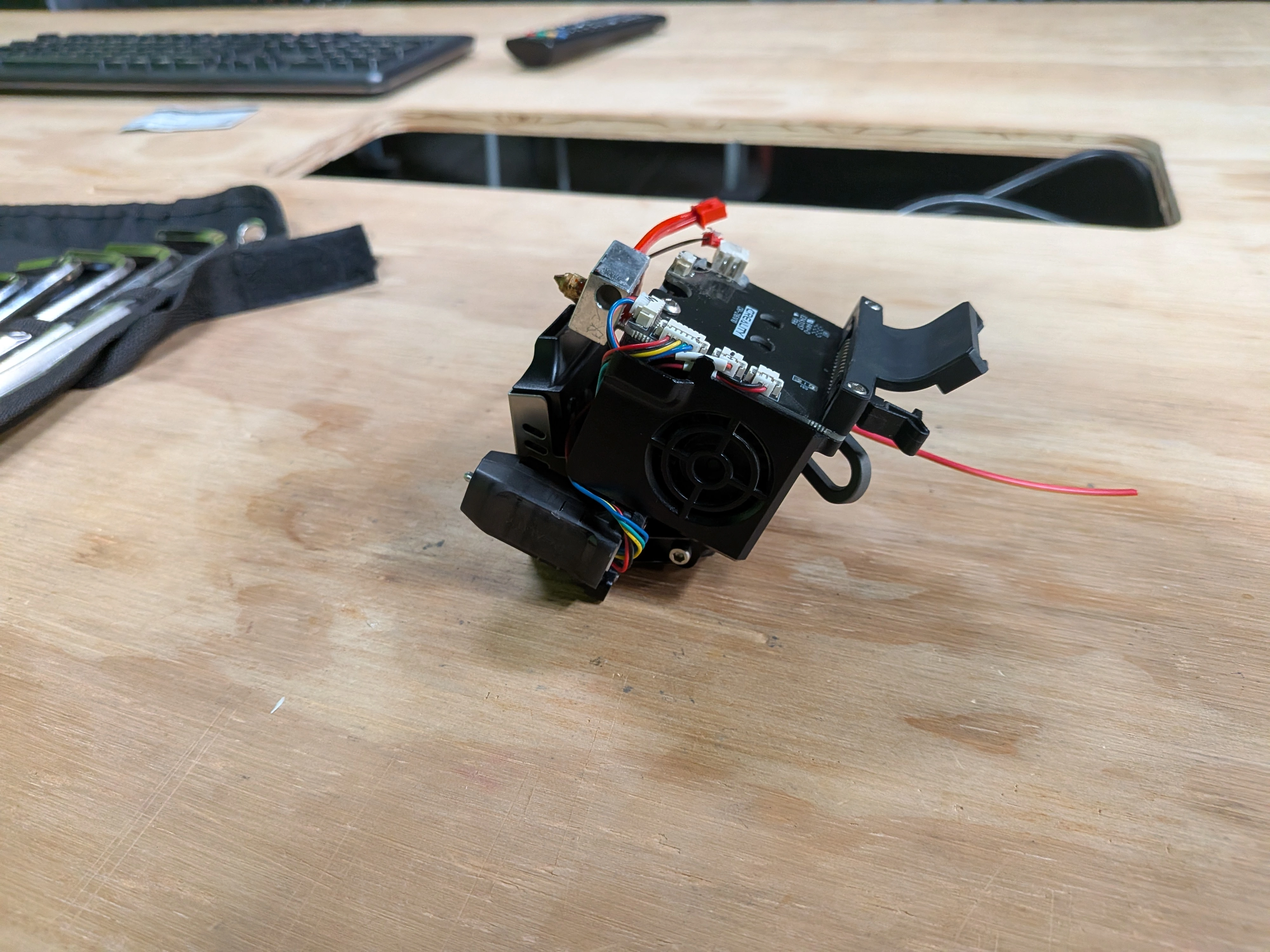
Getting to the hotend was a tricky process, as it required disassembling the whole extruder block and its assisting components. With the help of a YouTube video and some Allen wrenches, we where able to remove the extruder block from the 3D printer itself
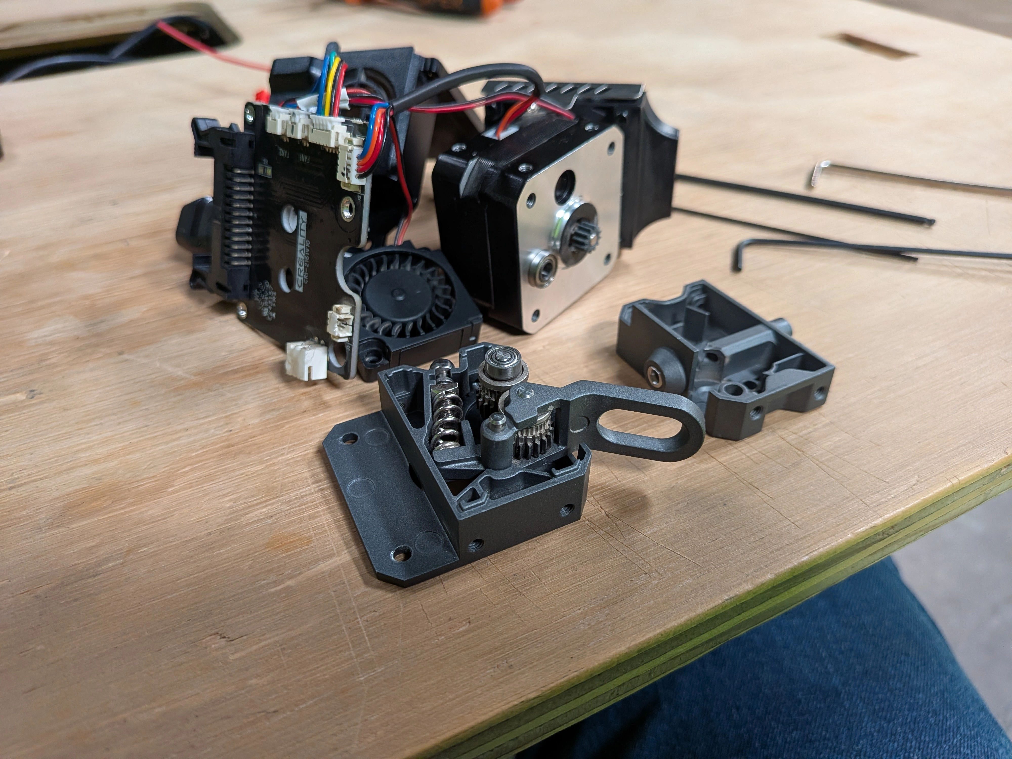
Then, it was still necessary to disassemble the block as to free the hotend from the rest of the components. The same YouTube video that helped us remove the extruder block also guided us on its disassembly. We not only needed to check the hotend´s condition, but also the extruder itself to discard damages or clogging in it´s mechanism.
Disassembling the extruder revealed it had no damage or clogging, and also gave us a look on how the mechanism works which I found really interesting.
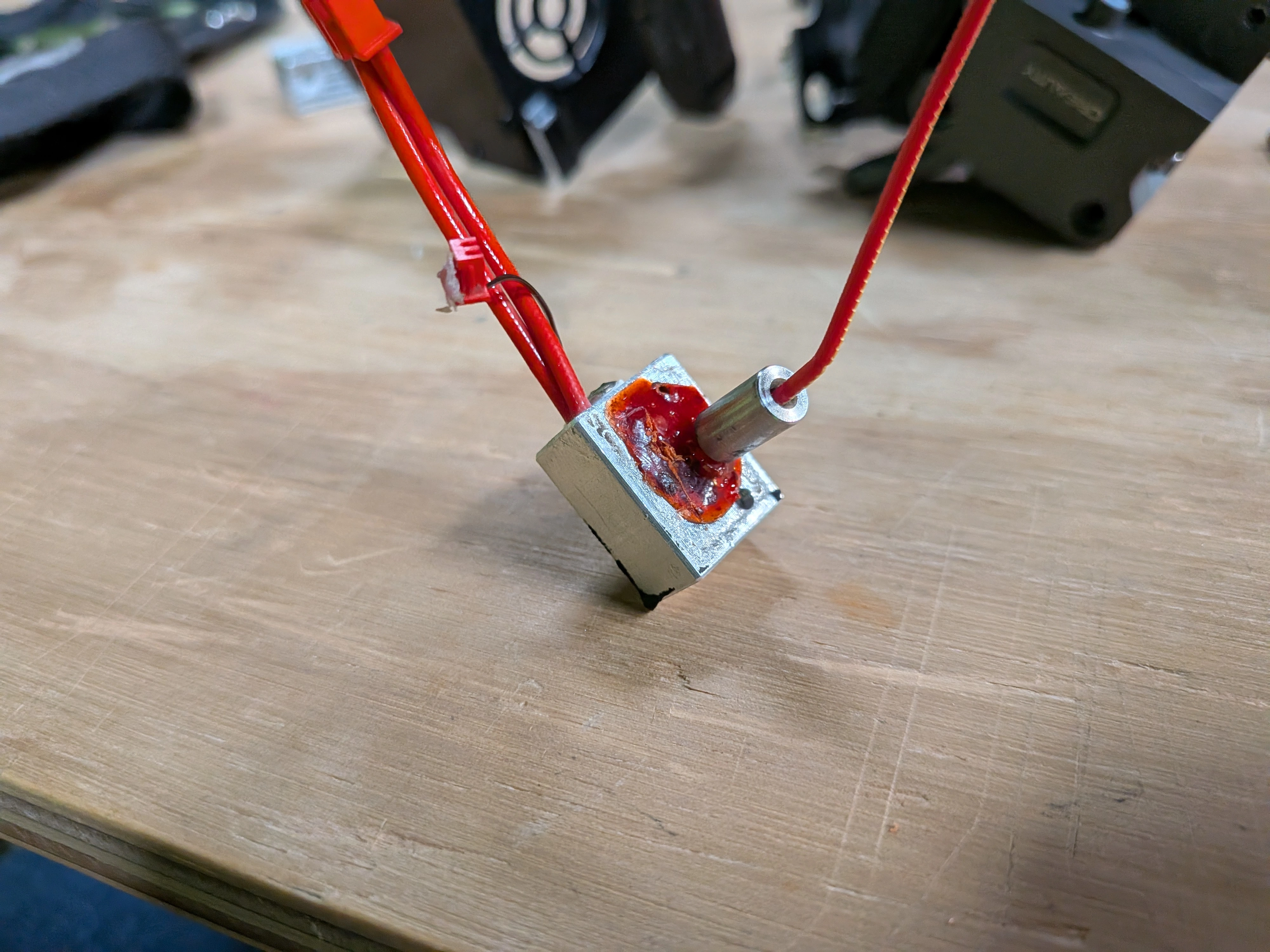
However, the hotend piece´s situation was not fortunate. It seemed that the clogging of the hotend was way deeper and complicated than we expected. Our theory was that the nozzle was not correctly attached to the rest of the piece, leading to leakage. Instead, we saw how a big clump of petrified filament extended all the way from the nozzle to it´s base. This clogging made it so that the printer had trouble releasing filament, but also created the leakage we saw.
We had a few options:
- A. We could connect the disassembled extruder block to the 3D printer and heat it up. Then, with a nail, we could remove the molten filament clog.
- B. We could use a heat gun or flame torch to heat up the isolated aluminium part of the hotend. Then we could remove the filament as well.
- C. Buy a new hotend, as they are not that expensive.
In the end, we decided that in it´s current state, our hotend was not worth saving. We where able to locate a new hotend online for around $15 USD, with free next-day shipping.
Reassembling The Printer
With the new piece in our hands, reassembling the piece was as strait forwards as following the disassembly steps backwards. The important step was readjusting the 3D printer, as the distance of the hotend was now different. The Ender 3 s1 Pro has it’s own self-configuring tool, but a few tweaking was also needed after this auto configuration. After a few printing tests, we figured out that a 3.95 z separation was optimal.
Now it was just a matter of sending the file to the printer. For this, we used a Raspberry Pi 5 with the Octoprint software to remotely connect to the printer via web page. In this web page, we were able to send files, se temperature charts and even hook up a webcam to get a monitoring view of the print, plus a video of the progress.
Ulitmaker Cura
Our 3D Printing preparation software of choice will be Ultimaker Cura. This is a free software that will help us control both our .stl file and our printer´s parameters. To use Ultimaker Cura, you can download it from Ultimaker Cura Main Page
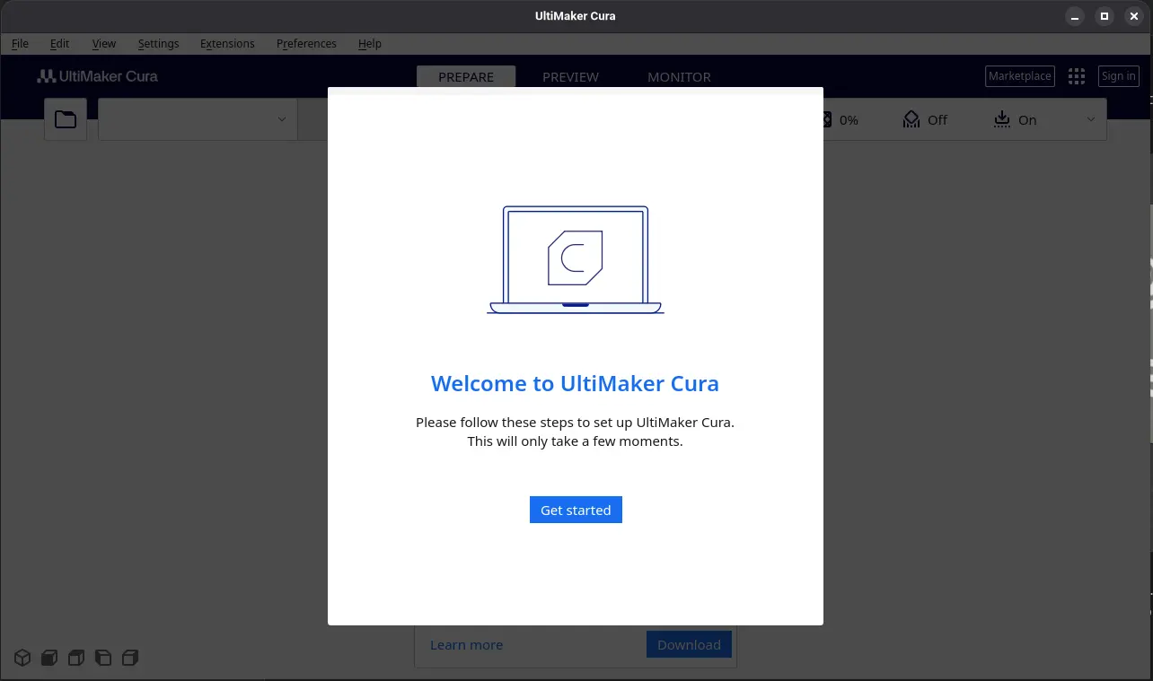
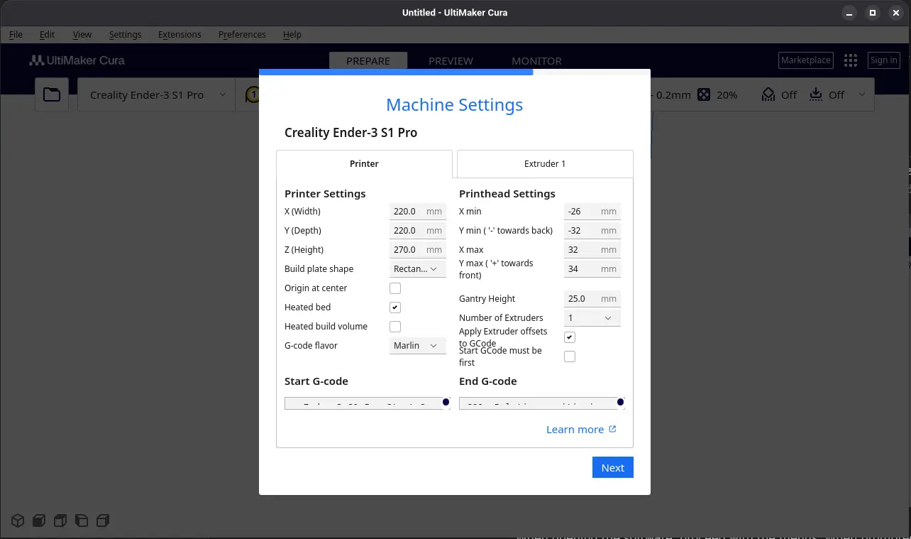
When opening the software, proceed with the menus. When prompted to go with an account, skip it. You will now arrive to a page where you must select your printer. Check your FAB´s printer model to correctly select the one you´ll be using. In my case it will be the Creality Ender 3 s1 Pro we fixed.
After this, a page with parameters will show up. Leave everything as is, or make adjustments as you may need.
You will now se your workspace.
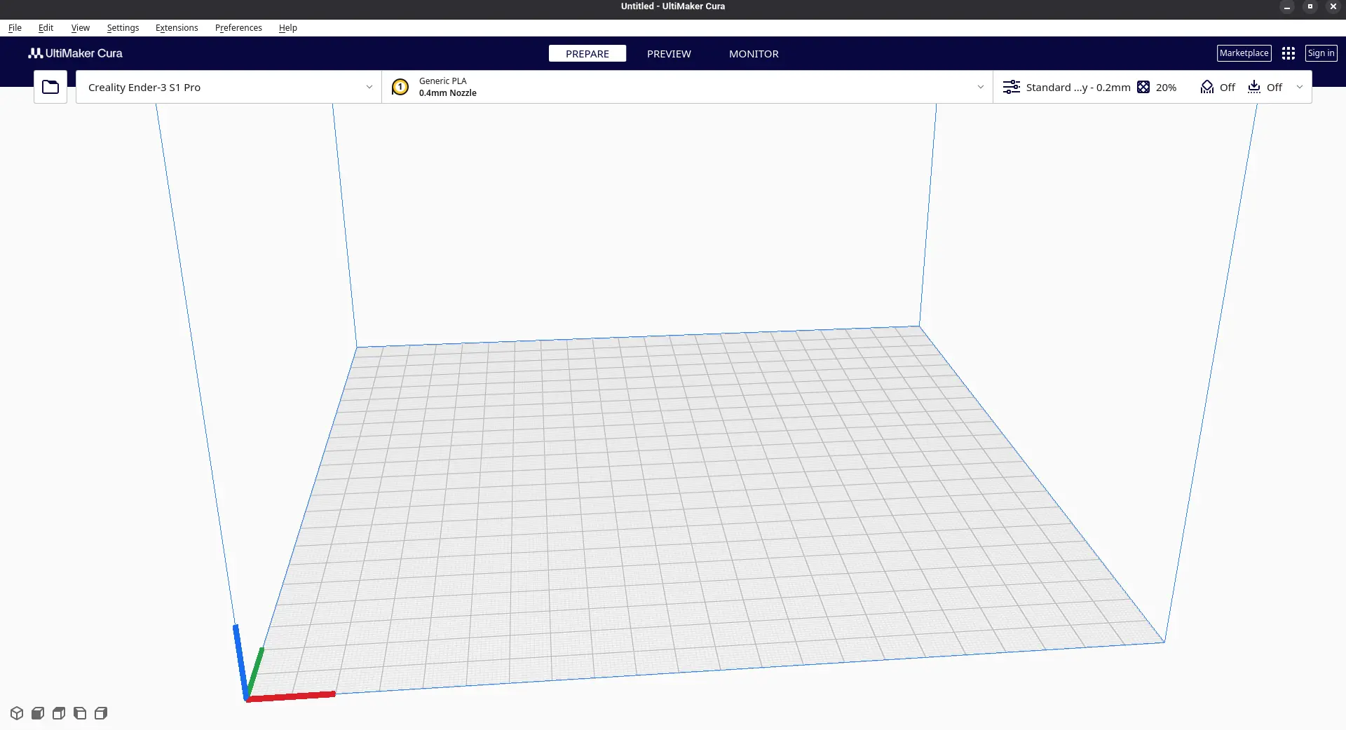
To start modifying an .stl file, simply drag and drop it into the workspace. After this, you can make somo modifications, like multiplying for multiple prints at once, and scaling the model for a better size.
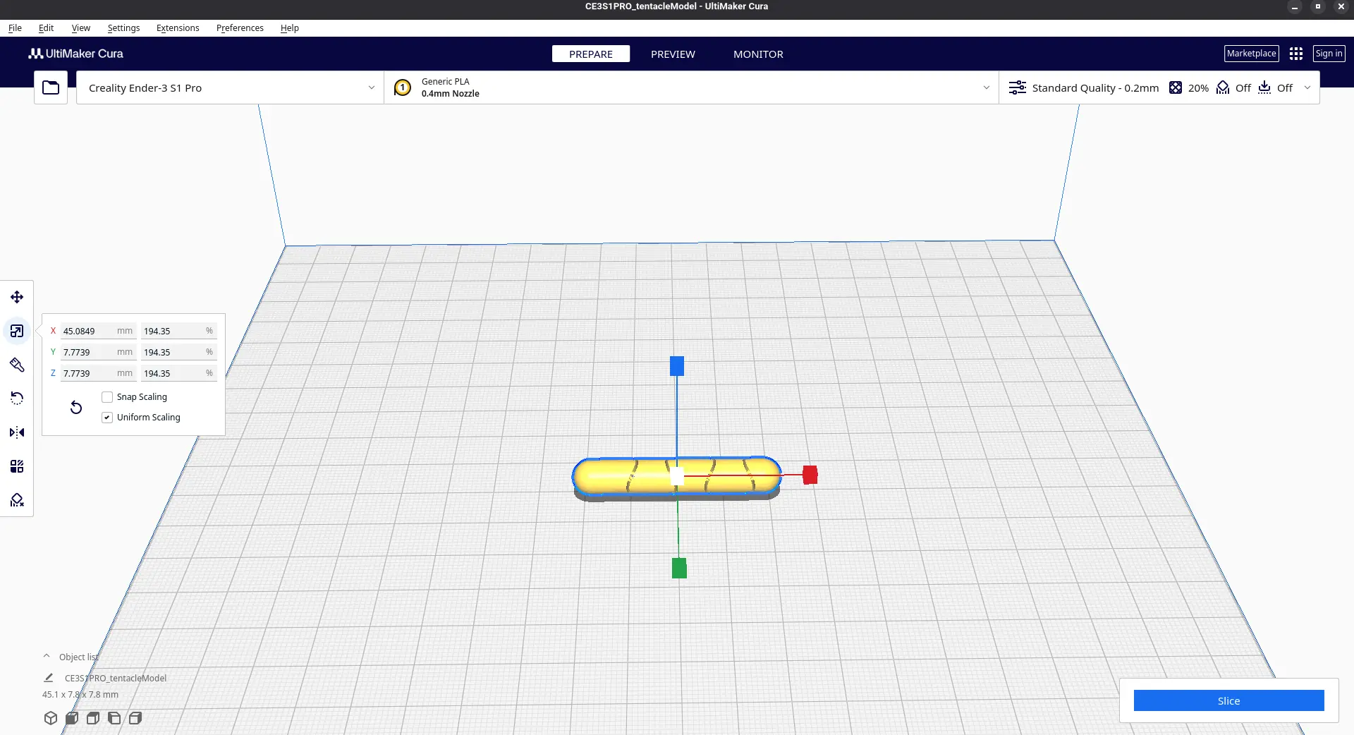
Now, it is time to configure our printing settings. First of all, the printing quality. Printing quality refers to the overall smoothness of the final product. A better quality will always result in better prints, but will take longer. Likewise, a lower quality will make prints faster, but with lesser quality. For prototypes, a lower quality is desired, and for final products a the best quality is desired.
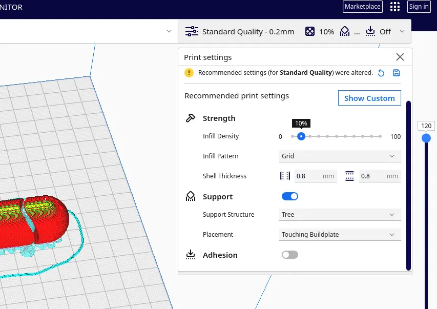
You can also modify other parameters. Playing with these parameters is ideal to find the right settings for your necessities.
- Infill density and shape: Refers to the amount and type of shapes inside your figure that will serve as a filling.
- Support. If you have hanging pieces, you must add a support. This will ensure you printer has a solid surface to print the actual piece. This support can be later removed when the print is ready.
- Advanced options: For more advanced features and tweaks, there is an advanced menu. Most of these options are not recommended to change, so be careful and do research before modifying them.
For us, our setting will be as follow:
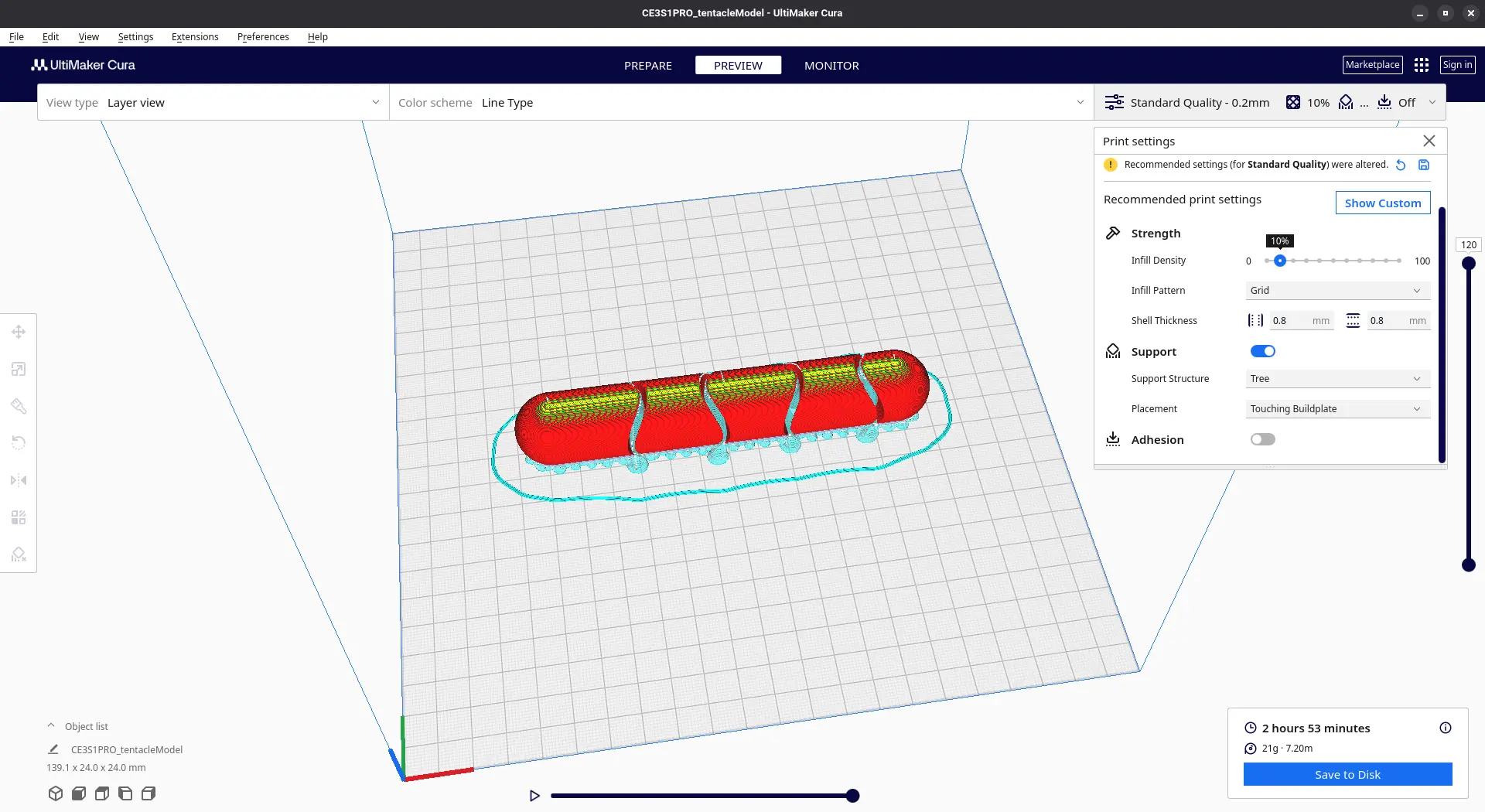
After configuring your settings, you can click the “slice” button to get a preview of your model. When everything is ready, you can click “save to Disk” to get the “gcode” of the print.
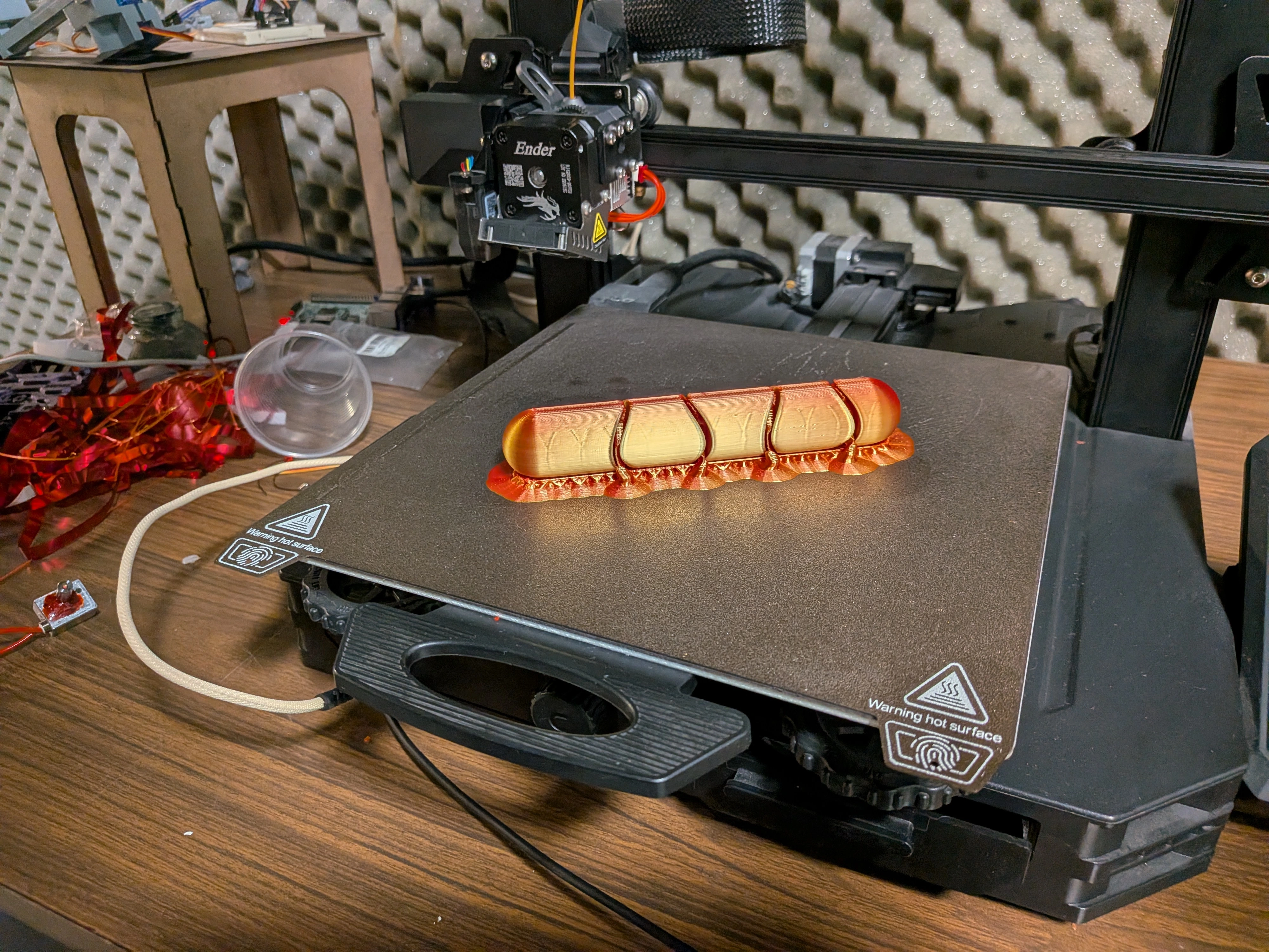
3D Printing
With every step ready, 3D printing is as simple as sending the file with the Octoprint website to our printer. This is what´s really fascinating about 3D printing. Having access to a 3D printer is one of the biggest privileges a maker can have, allowing you to create everything you need for your ideas to come to life. It took a while to set up my printer (mostly because of the reparation involved), and I was late on this week´s assignment. Time only allowed me to print the tentacle model, instead of the 3 prints planned for the week. But in the end, after 3 hours of printing, I got myself my very first 3D printed piece!
Now that the 3D printer is set up, and I involved myself so deeply into making it work correctly, any other prints I might need for this FAB will be a walk in the park!
3D Scanning
Up to this point, we’ve talked about multiple ways of creating an object from scratch in order to bring it to life by 3D printing. This skill is essential when developing any kind of project where there is an idea that needs to take shape. But what if the idea already has a shape? There is a big chance that, once in a while, your projects will require modeling things that already exist. This can happen for many reasons, one of them being needing a model of that object in a 3D CAD software in order to create something around it. The more you think about it, the more useful applications of bringing a real-life object into a 3D working space appear.
3D scanning solves this issue for us. The process of 3D scanning is as straight forward as it sounds: you take an object, use one of many tools to scan its shape and translate it into a 3D object (usually an .stl file). The world of 3D scanning is as vast as it is underrated.
Getting Started
To start 3D scanning we first need a platform to work with. 3D scanning comes in different forms, some needing dedicated hardware to work. I recommend taking a look at this page for a better explanation on how this 3D scanning technologies work. For us, it is better to look at the available 3D scanning tools in our Lab.
Polycam
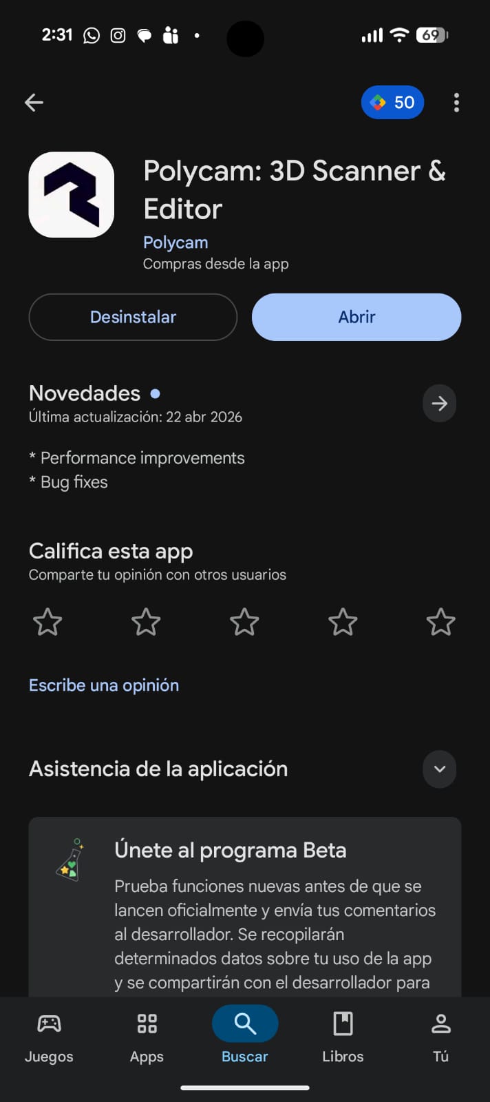
But what if you don’t have access to one of this 3D scanning tools. Luckily for us, there is a free way of scanning 3D objects at the tip of your hands: Polycam. This is free app you can download on your phone, from which you can do light 3D scanning. This is not a professional alternative to a 3D scanning machine, but it is an easy to use and fast alternative for prototyping or recreational uses.
Disclaimer: While you can use Polycam freely, it is limited. There is a paid option that allows for more scans, export in more formats, and so on. If you wish, you can use your free trial to test all of these advance options. For me, i’ll go as far as my free plan will allow.
To start using Polycam, search it on your phone’s application store (App Store, Play Store, Mi App Store, etc.). Simply download it and open it.
Register yourself with an email. Make sure to also give the app you device’s camera permission.
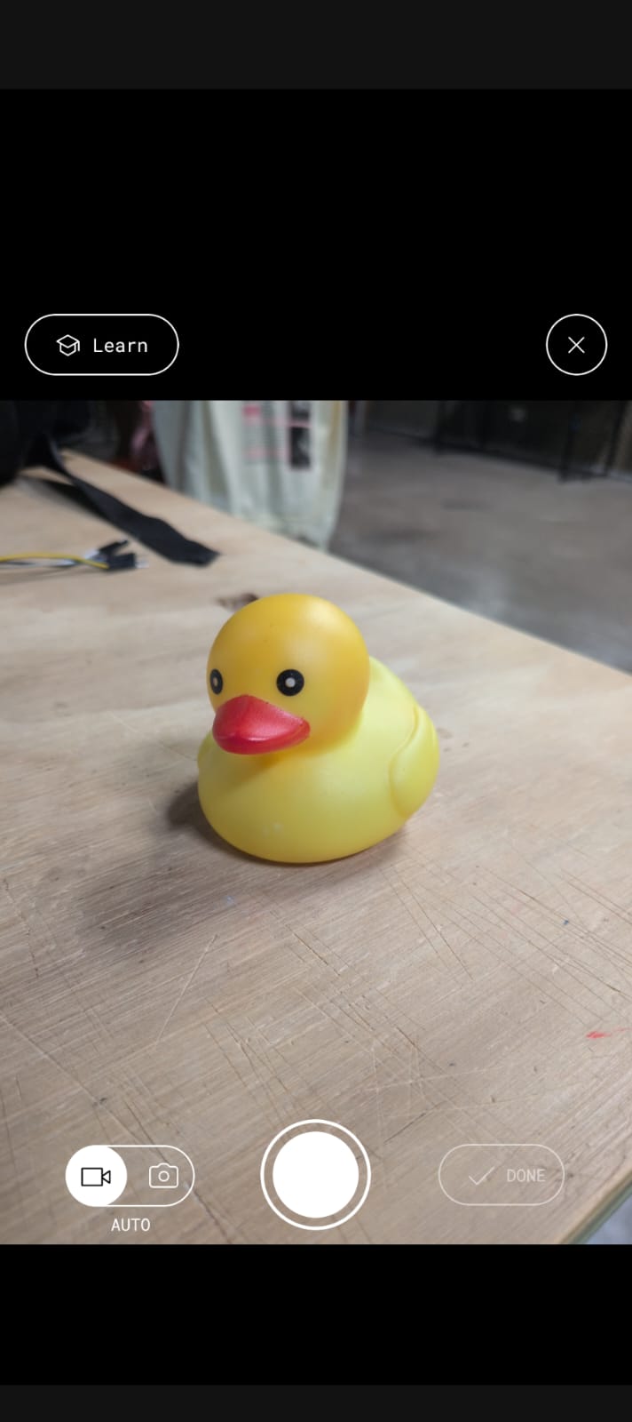
Now, start recording. The app will automatically take pictures of your object as you move. Some things to take into consideration are:
- Don’t move to quick or the images will be distorted.
- Capture as much sides of your object as possible. This will prevent the final model from having jagged sides.
- You can stop the recording at any time to reposition yourself or you object. Be mindful, though, drastic changes on your objects position can result in distorted results.
- The place you rest your shape on when scanning is also important. For a better result, use a white cover for your surface, like a blanket or a large sheet of paper.
Once your images are taken, you can upload them and wait. You can close your app if you wish. Polycam will upload your images into its server and transform your image into a 3D file. You’ll get a notification when your scan is ready. Re enter into your app and there you have it! A free 3D scan of your object.
Here’s where we hit a roadblock though. To export your file into something useful, like .stl, you now need to pay a subscription. If you wish, you can pay this subscription or use your free trial to export it in .stl or some other file format you desire. For the time being, I won’t be getting any file as to not pay or use my free trial. But this doesn’t mean we can do nothing with our scan. We can share a link of your scan with other, by clicking the “Share” button and copying your link. Here’s a link to my personal best scan using Polyscan!
Einscan SE
Polycam was useful for dipping our toes into the world of 3D scanning. For a more “real” use case though, Polycam stays short. The problem with 3D scanning is that the quality of the scan is fully tied to the quality of the tool. Our phones, as power full as they have become, will never function as proper 3D scanning tools.
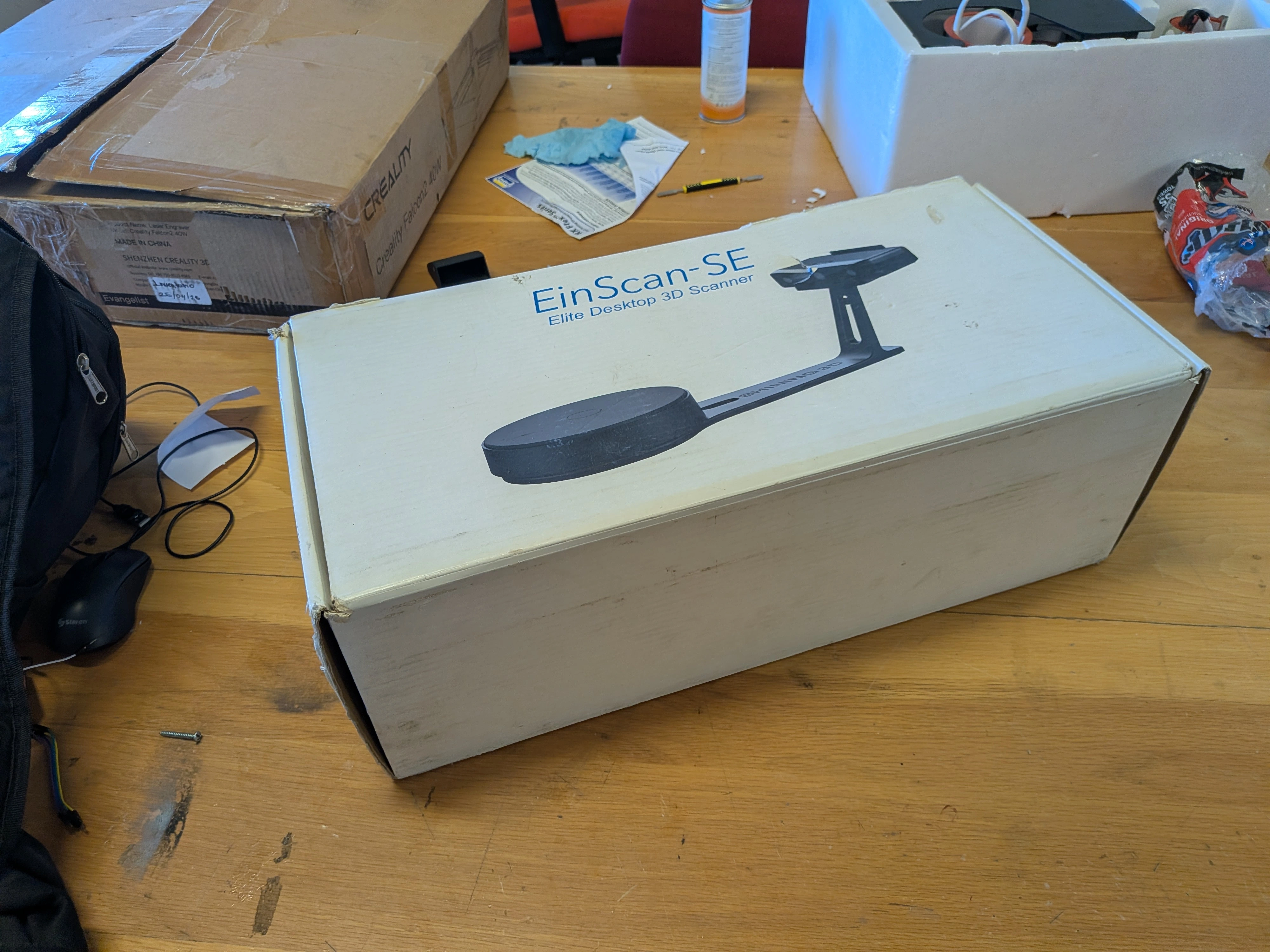
Luckily for us, we have some 3D scanning tools at our disposal here in our lab. The tool I will be using now is the Einscan SE. This one is a big one, includes a rotating base and a capturing module.
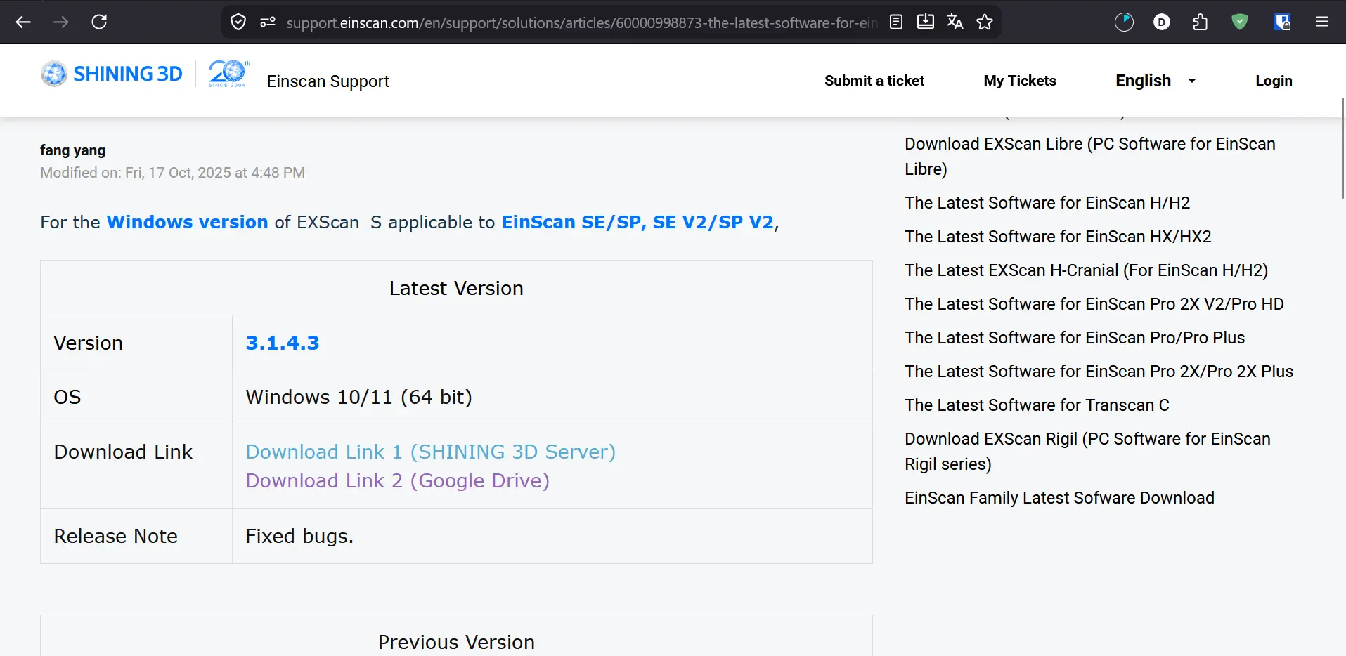
To start using the Einscan tool we need two things. First of all, we need to download its software. We can do this directly from Shining 3D’s official download page.
The second thing is assembling the scanner. To do this, we first need to take it out of its box:
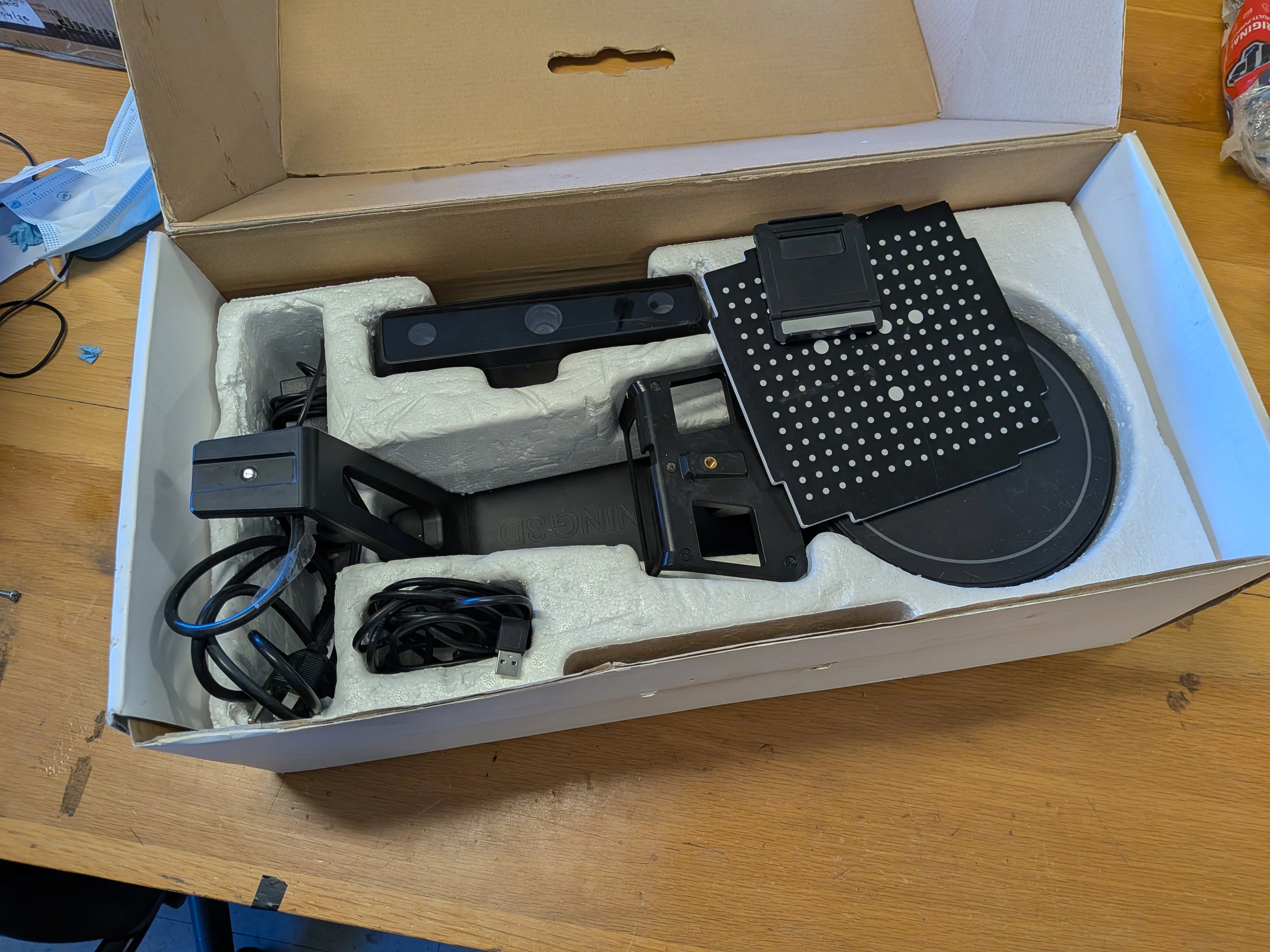
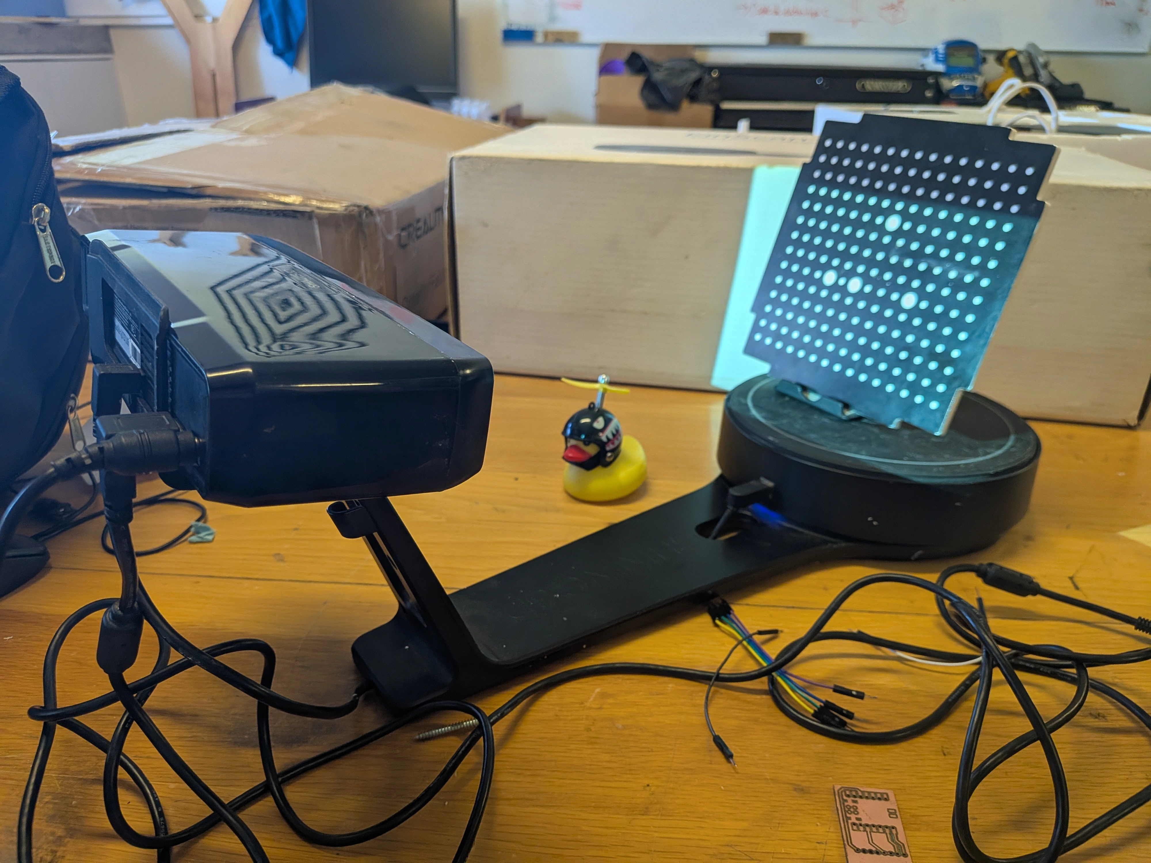
Assembeling the scanner is quite straight forward. The base piece needs to atach to the holdnig pice for the scanner module. The scanner module then goes in the holding piece. Every cable is then connected to the scanner module (the base cable, the USB cable for our computer and the power supply). The dotted square and the “phone” stand will be used later. Our scanner should look like this:
Once the scanner is built, turn it on. Connect the cable to your computer and start the downloaded program.
EXScan
To use the EXScan software, we first need to create an account. There is a “guest” login option, but its limited. For all the things we want to do, creating an account is necessary.
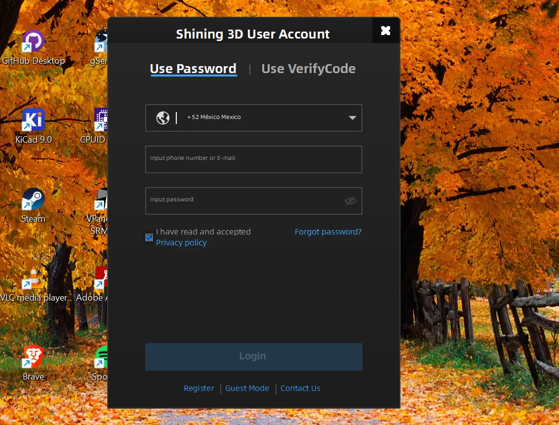
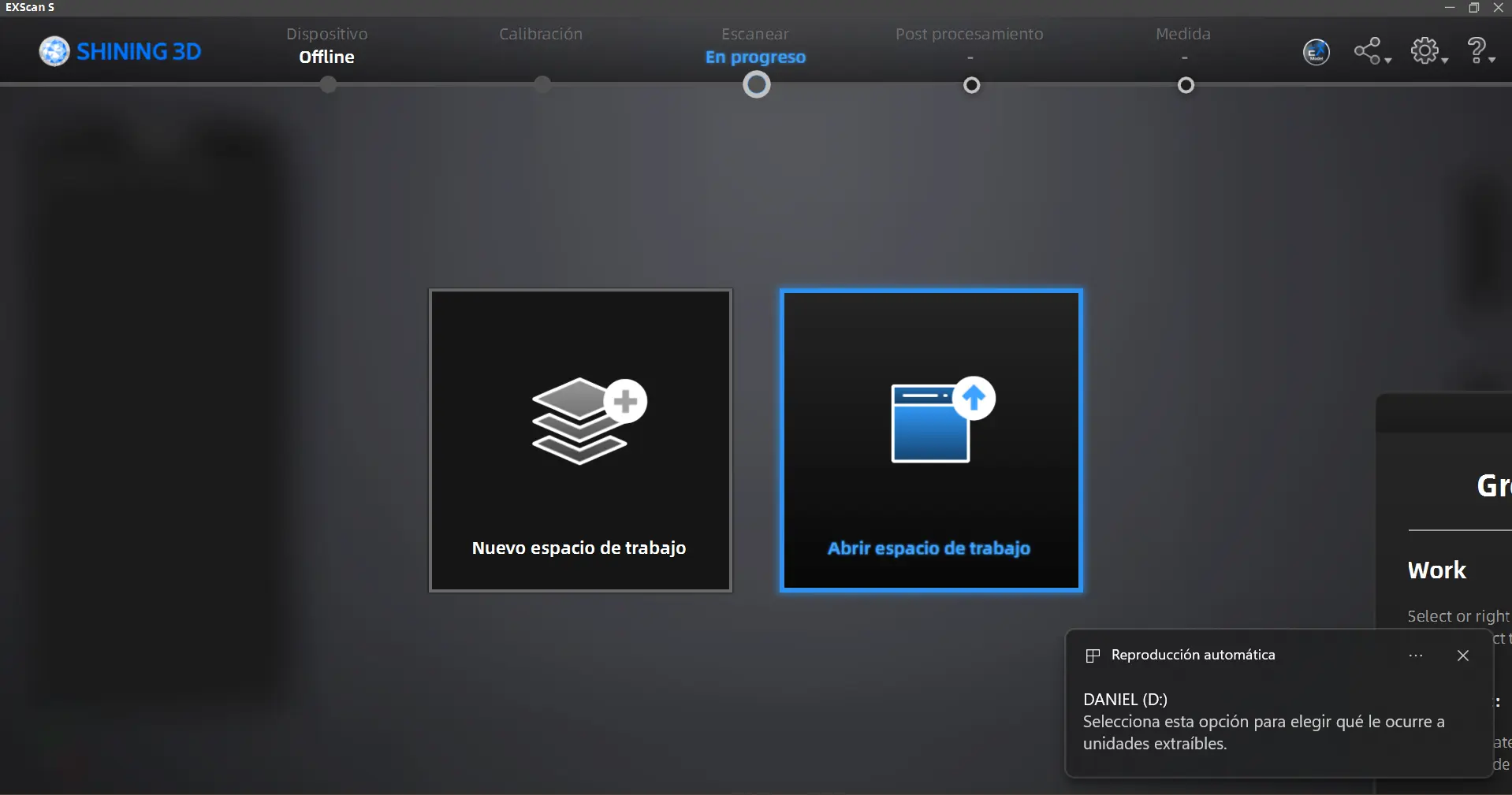
Once your account is verified, you will be prompted into the software’s main screen. Select the “New workspace” to start, or selectr “Open workspace” to continue working on an existing project.
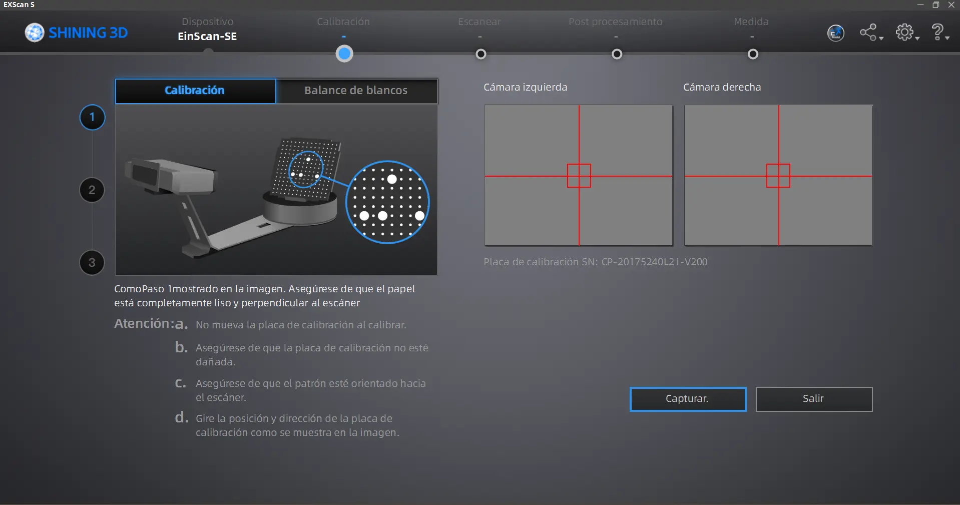
Now we will have to calibrate our machine. To do this, follow the software’s instructions as show. Now its time to use the dottet square and the supporting base. Place the base at the center of the rotating base as indicated in the pictures. Once your dottet square is placed correctly, hit the “Capture” button. The rotating base will start to move. Do not interfere with the process. Repeat the process 3 times, changing the position of the dottet square as requested by the software.
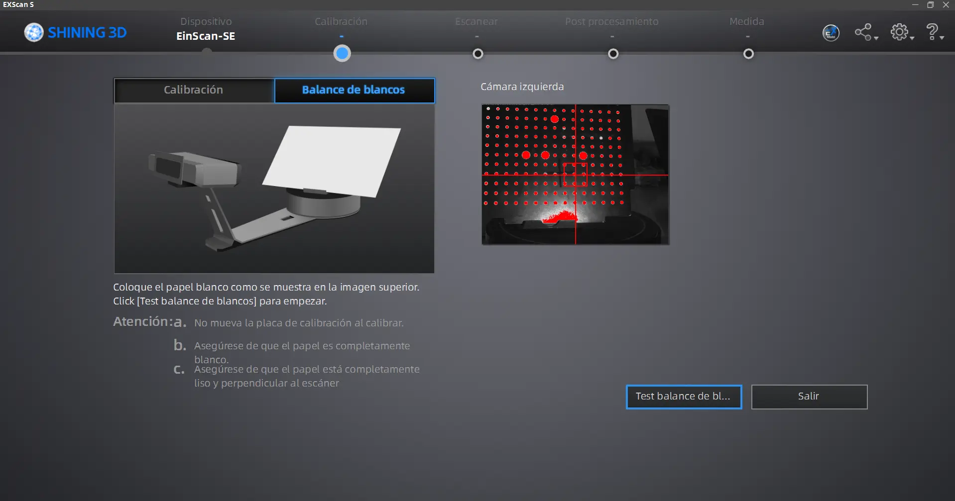
Once the calibration is ready, you will need to calibrate the “White balance” values. To do this, get yourself a white office paper sheet. Place the sheet of paper as requested by the software. You can hold the piece of paper for better results, just keep your hands out of the camera’s range.
Once this calibration is done, we are ready to scan our objects!
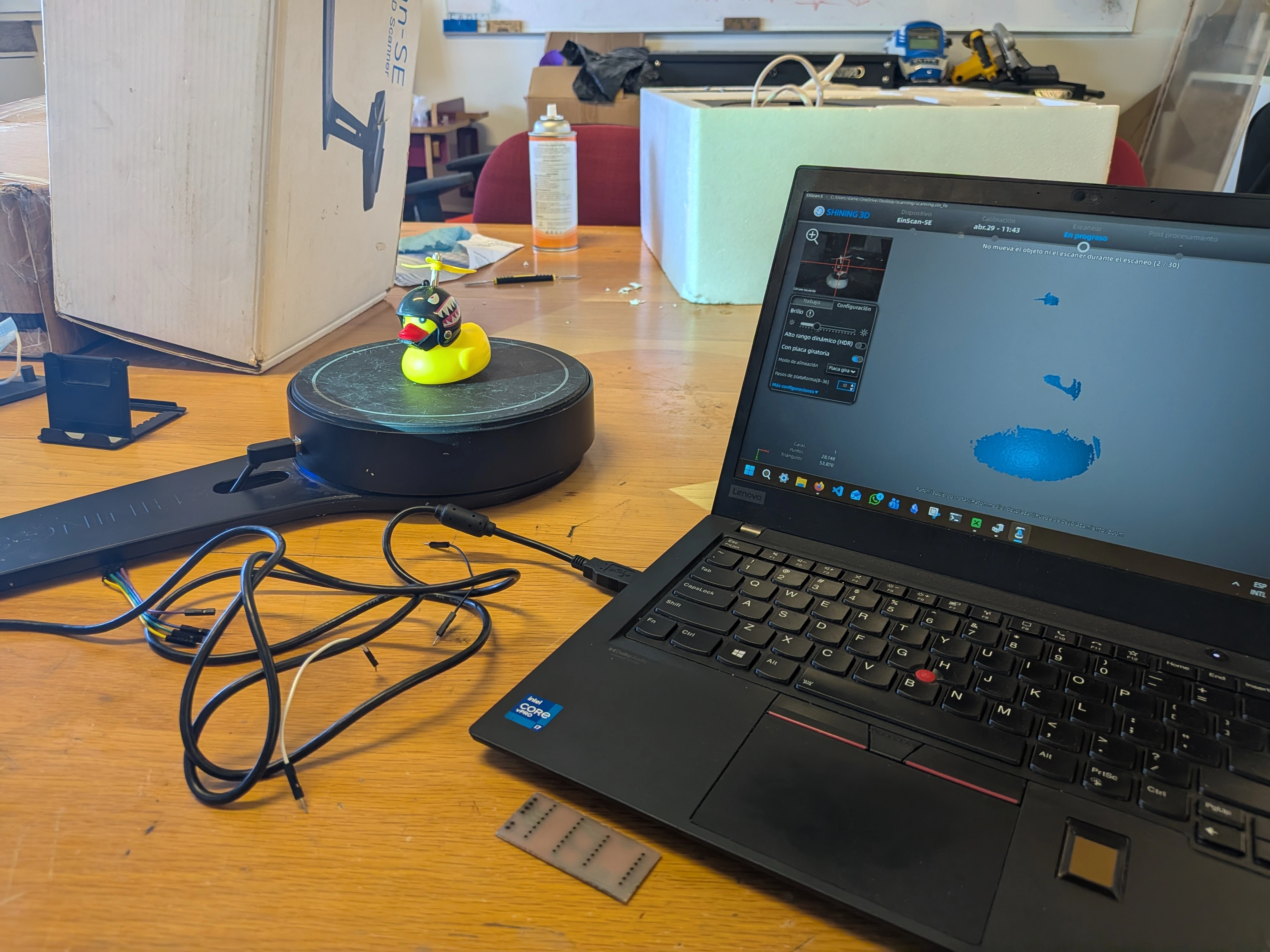
Scanning Our Objects
Place your object in the rotating base of the scanner. Now, go back to your computer. There are two key parameters we need to play with: Rotation count and brightness. Rotation count is simple, is the amount of times the base will rotate. I recommend setting this value at 15, for a good balance of scanning quality and speed. Brightness, on the other hand, heavily depends on your object. Reflective materials might need less values, where as opaque materials might need more. Play around with these settings to find your personal sweetspot.
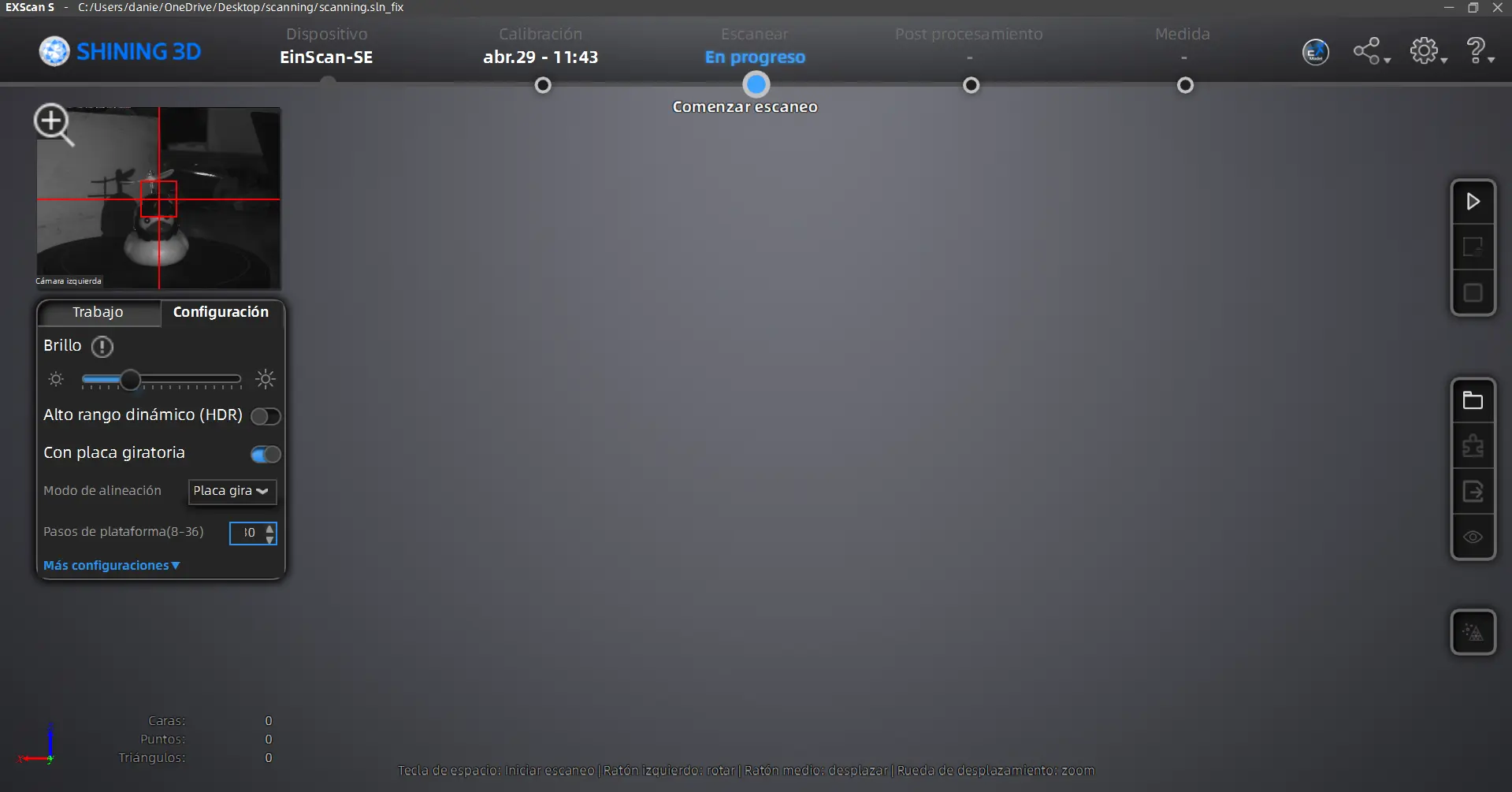
Once your parameters are ready, click the “run” button on the right side menu. The camera will begin to flash a light to your object, and rotate it accordingly. DO NOT interfere with this process. In your screen you will be able to see a preview of your current scan.
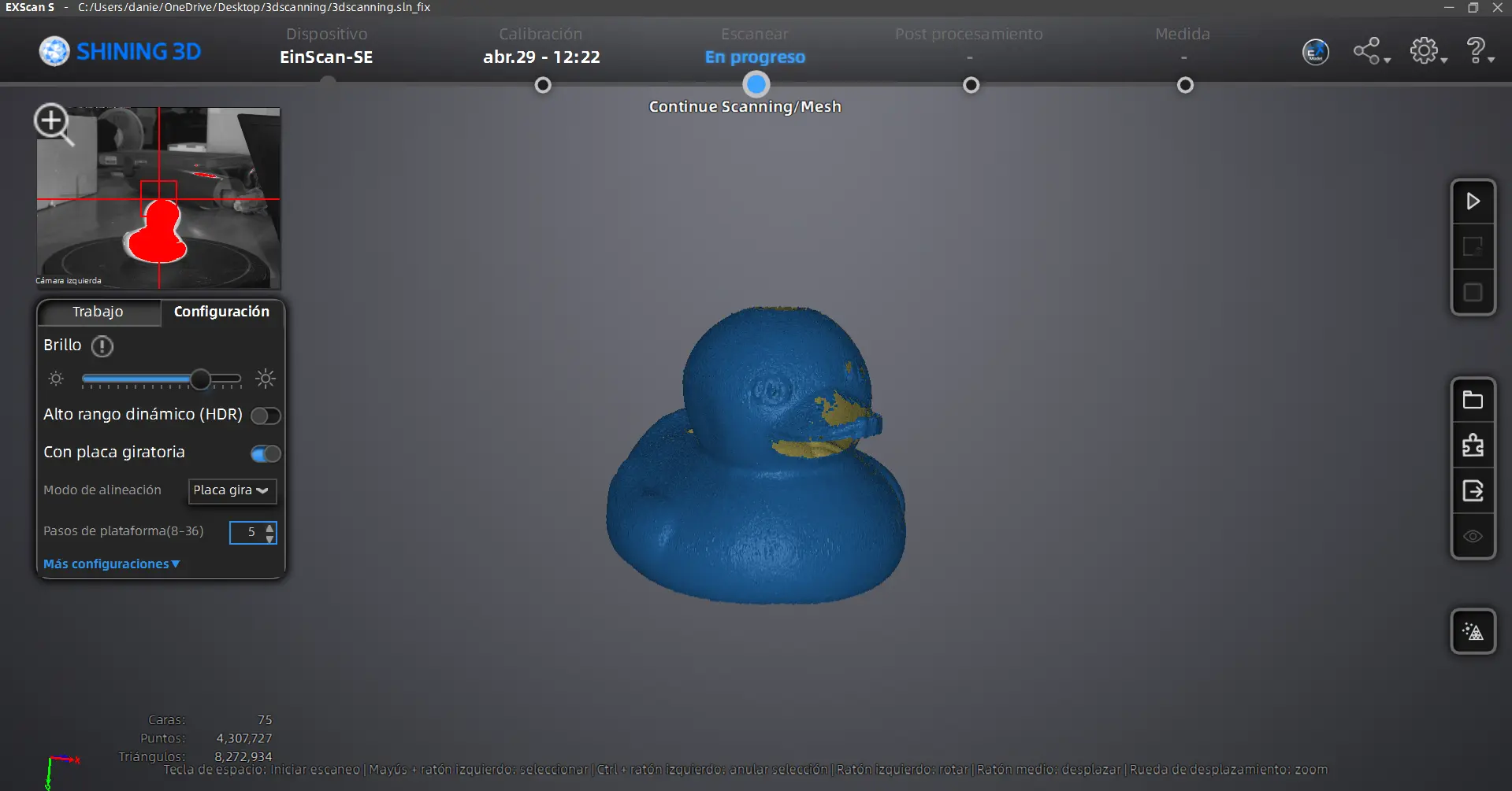
You can do multiple runs at various configurations to get a better joint result. It is normal to see unfilled parts in your scan preview, those will be “fixed” later. When you are satisfied with your scanning, click on the “mesh” button, the furthest down of the right side menu. This will transform your scan into a mesh object. Select your objects mesh type and quality according to your personal needs. Once the process is done, your 3D model will appear on scren.
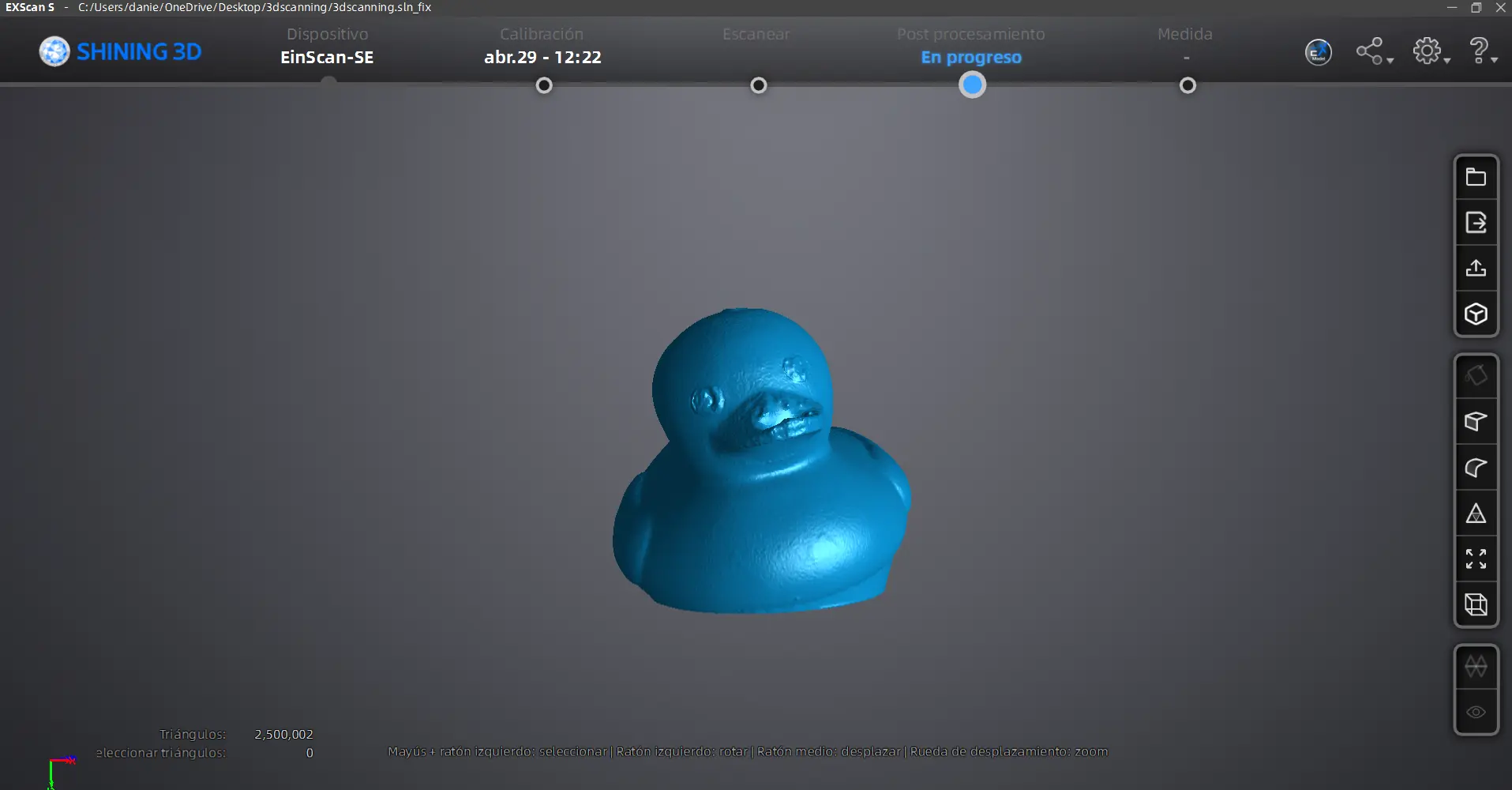
And we are done! we can export this 3D object as an .stl file by clicking the “export” button on the right side menu. Now you can import this to any other software you want, like Blender to further modify it or Ultimaker Cura to print it.