Week 4: Embedded Programming
Embedded programming is the act of writing a piece of software into an specialized hardware system. This hardware piece, often a micro-controller, translates the logical operations of it's programming into digital / analogue signals that can be outputted / inputted into electronic components. With this, we can create deterministic functionalities to our electrical designs.
In order to do embedded programming we need: A micro-controller and a programming language. The micro-controller will work as the brain, and a hub for any device or wiring that will go in or out of it. The programming language will help us write the instructions the brain will follow.
For more information on how we can choose our ideal combination of micro-controller and programming language, check out our Lab’s Group Assigment Page. From this page, I learned the difference between the most common micro-controller families (like ESP, RaspPi, Arduino). Also, I learned about the various development platforms for said micro-controllers, plus the different available programing languages you can use to program them. Choosing the right combination of micro-controller + development platform + programming language is essential to facilitate your embeded programming expreience.
Starting with Embedded Programming
The ideal way of doing embedded programming is to get a micro-controller, a breadboard, electrical components and wires; and just play around with it. But even if you do not have access to a micro-controller, you can still begin prating embedded programming
Wokwi
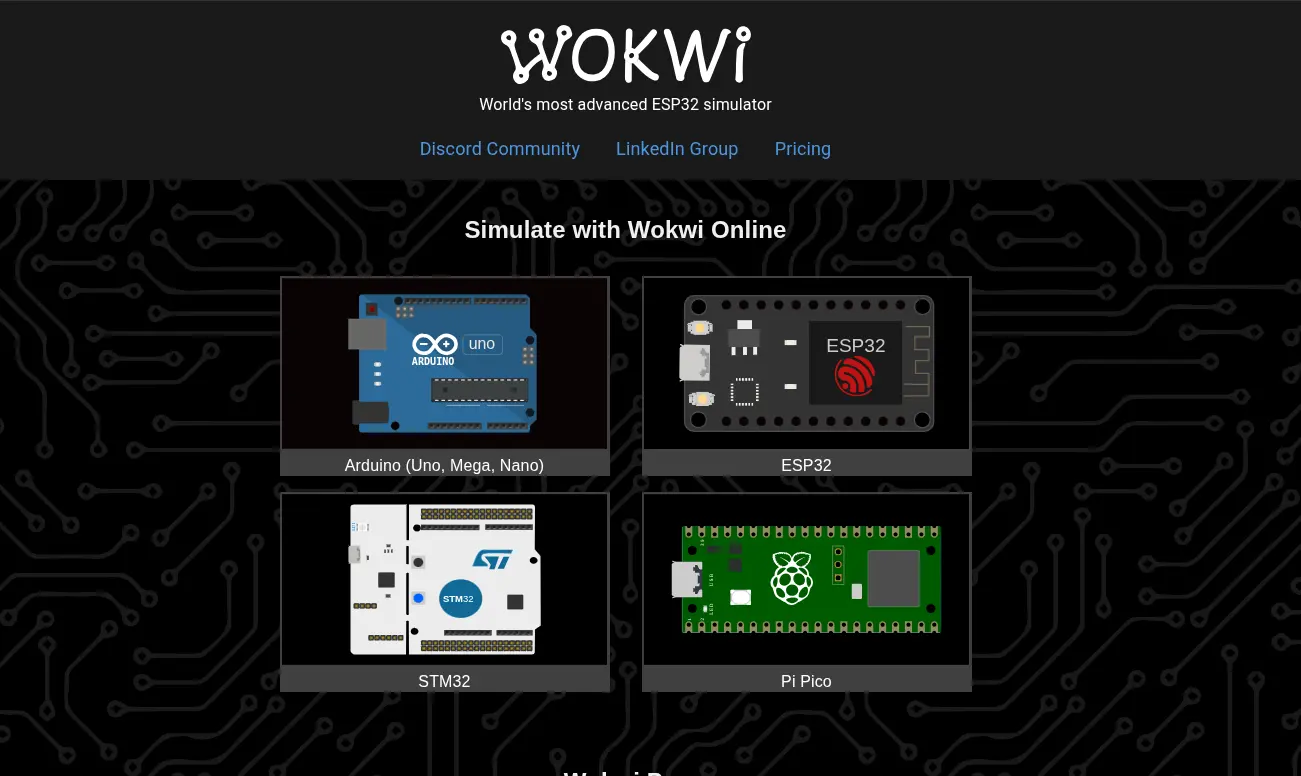
Wokwi is an online embedded programming platform, where you can play around with a variety of micro-controllers and electrical components. Wokwi functions as a “testing ground” for your projects, allowing you to sketch your ideas for free, to then translate them into a physical prototype. Using Wokwi is real simple. No account is required and everything is available for free. To start using Wokwi you can simply head to their main page.
Getting Started with Wokwi
Once in Wokwi´s main page, you will be able to select your desired micro-controller family.
For more information on how to select your desired micro-controller, you must check our lab´s group assignment page for this week. For us, however, will be using both the ESP32 and Pi Pico platforms. After selecting our desired platform, we can now choose our starting template. We can choose from a variety of examples that teach you how the programming language works and how to connect and work with multiple components. For this first example, we´ll be working with the Pi Pico platform.
Choosing our Blank Project
Once we´ve decided our micro-controller platform, it´s time to choose our blank project to start working. There are two main types of blank projects, the only difference being the programming language: Arduino and MicroPython. Choosing the right programming language for your use case is important. Your can refer to the programming language section in the group assignment page. For this first example, we´ll be working with Arduino.
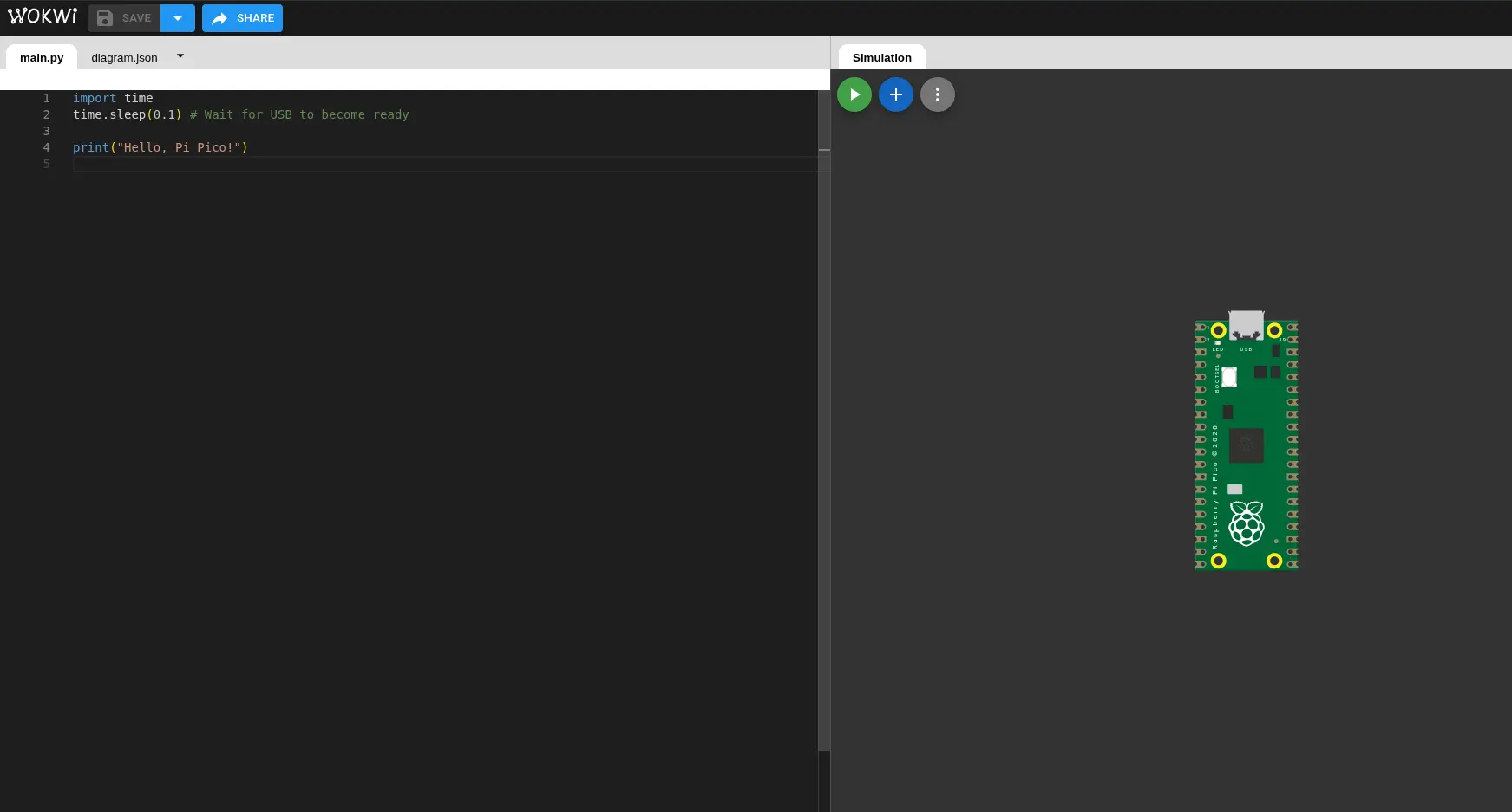
Find the corresponding template for a blank, MicroPython project and click it. You will now be in your workspace:
Embedded Programming Basics
Essentially, embedded programming works by translating code into electrical signals. We can create our own script with a mix of established language syntax (For statements, if statements, logic operands, math, etc.) and other library based functions to work with the hardware. This results in a program that, when flashed into the micro-controller, will begin to operate.
There are two essential parts of the script: The setup and the loop. The setup is every variable declaration, function and supporting logic that will be used. The loop is the actual execution of the micro-controller. Everything declared in the loop will be run infinitely as long as the micro-controller has power. Some programming languages have this parts well established, like Arduino with it´s void setup() and void loop().
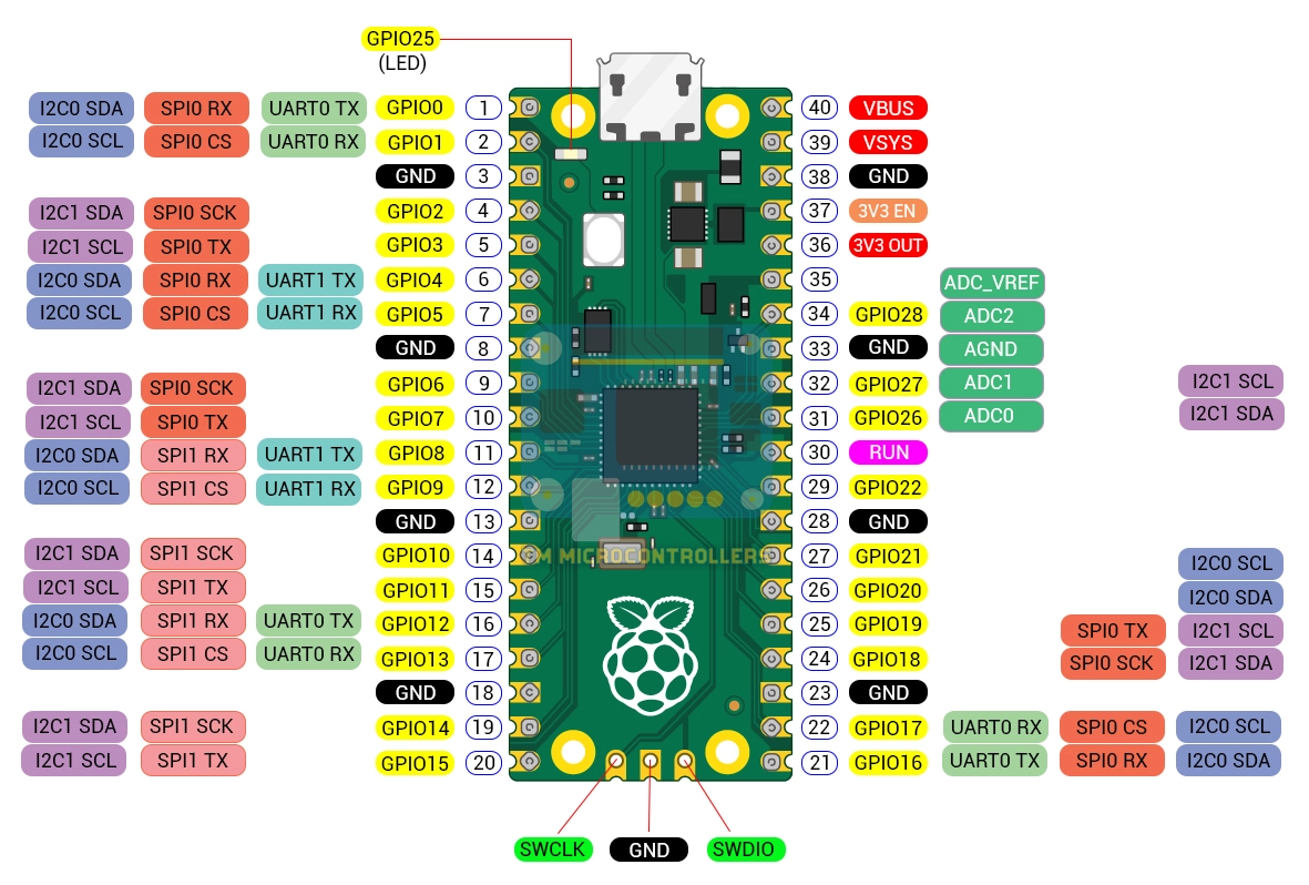
There is one more thing we need to get in order to start. We need the **pin layout** of our micro-controller. The pin layout is a schematic that lists the uses of every pin in our micro-controller. Multiple pins can have multiple functions, and some pins might be used for something specific, like a Ground Pin. Knowing what pins we can use will be necessary for future steps. The best tool for getting to know not only the pin out, but the whole functioning of your micro-controller is to look at their **data sheet**.
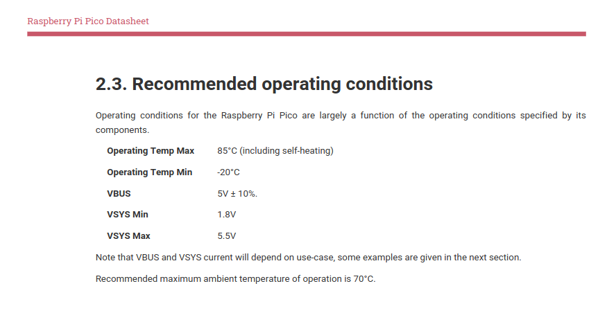
A data sheet is a document full of everything there is to know about you micro-controller. From pin layouts, operation temperatures, power supply and consumption, dimensions, etc. If you really wish to understand your developing platform, this is the place. You can easily find your micro-controller's data sheet on the internet, by searching "Your micro-controller name + datasheet". For our Raspberry Pi Pico, you can look at Raspberry Pi Pico’s official datasheet here. From this datasheet we can learn, for example, the optimal operational conditions of the Raspberry Pi Pico. Said information would have been usefull to know if we where working on a project meant for extreme conditions.
Once you have a good understanding of how to operate your micro-controller thanks to their datasheet, I recommend having on hand your micro-controller´s pin layout as an image. Search "Your Micro-controller Name + Pin Layout" on Google and having it besides you while you work will help you streamline your work flow.
Getting Started
For starters, we´ll be looking at two of the most important functions in the Arduino Language: pinMode() and digitalWrite(). With this two functions, we can start giving life to some components, like LEDs.
pinMode()
Firstly, the pinMode() function. pinMode() declares the functionality a pin will have. The pinMode() function takes two arguments: the Pin number and the Pin Mode. An INPUT pin is configured to receive a digital signal, whilst an OUTPUT pin is configured to send it.
For example, if we wanted to declare the GPIO27 pin to OUTPUT, we´ll write pinMode(27, OUTPUT) inside void setup().
Note: It is a good practice to make variables for your pin´s number. That way, if in the future that pin would change, everything in the script can be change with just updating the variable value.
// This is our Pin variable
        #define LED 27

        void setup() {
            Serial1.begin(115200);

            // This is our pin mode configuration
            pinMode(LED, OUTPUT);
        }
digitalWrite()
Secondly, the digitalWrite() function. digitalWrite() changes the current output of the pin, to no output (LOW) or output (HIGH). It´s like pushing an on/off button. digitalWrite() will only work with our OUTPUT, and takes two arguments: the Pin number and the values (LOW, HIGH).
For example, with our pin already declared, we can “turn it on” using digitalWrite(LED, HIGH).
// This is our Pin variable
        #define LED 27

        void setup() {
            Serial1.begin(115200);

            // This is our pin mode configuration
            pinMode(LED, OUTPUT);
        }

        void loop() {
            digitalWrite(LED, HIGH);

            delay(1); // Delay for stability
        }
We can play with this function and some timing to create effects like blinking lights.
void loop() {
            digitalWrite(LED, HIGH);
            delay(1000); // One second delay
            digitalWrite(LED, LOW);
            delay(1000);
        }
Adding Components
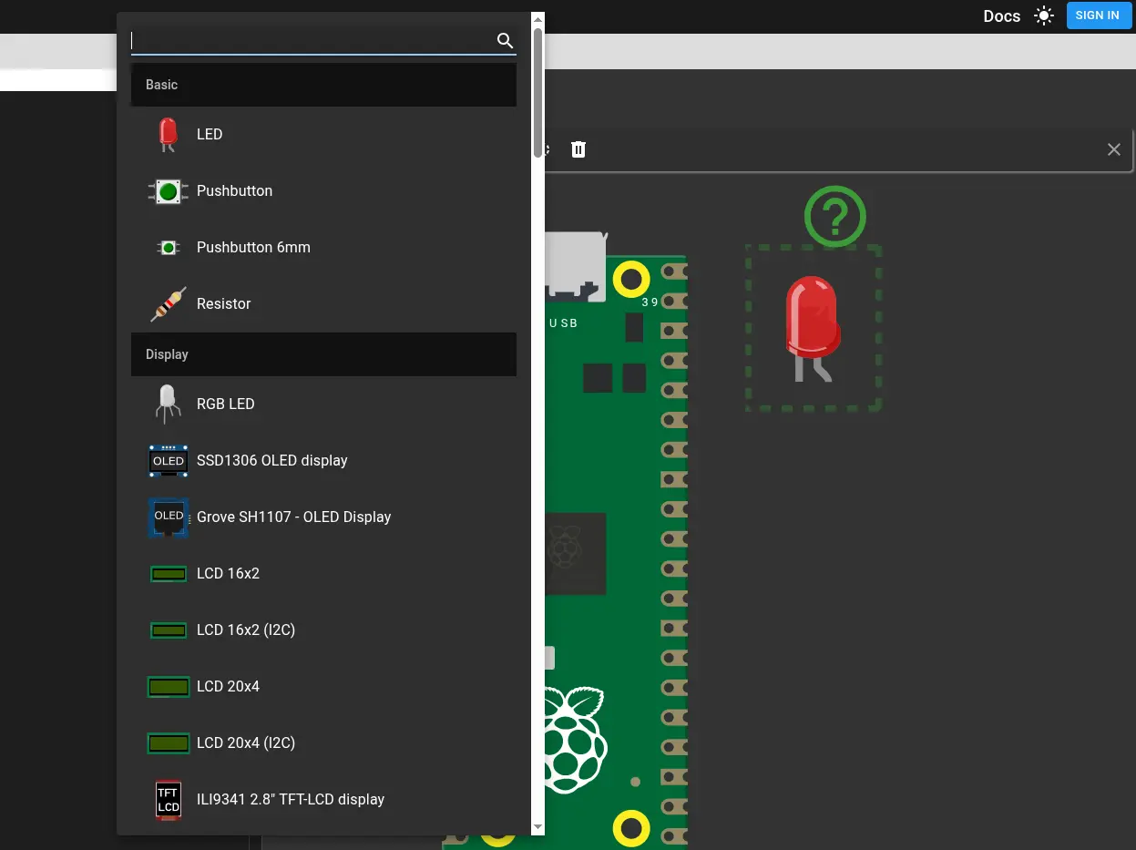
Wokwi offers a variety of components we can use. To add components, we can look at the blue “+” sign in our micro-controller window. Here, a list of components will appear. To use a component, simply click it. Your component will appear in the micro-controller screen. You can drag and drop as you wish and change somo properties like values and colors.
Now we must connect our component to the micro-controller. To do this, go to either the micro-controller pin or the component pin and click the box that will appear. Now, trace the wiring with your mouse until you arrive to your destination pin. Now click the destination pin and your connection will be ready. You can modify each wire color and patting.
We´ll proceed to put the LEDs Anode into the GIPO27 Pin, and the Cathode into any GND Pin. For reference, our GND cable will be Black, and our GIPO27 cable will be red.
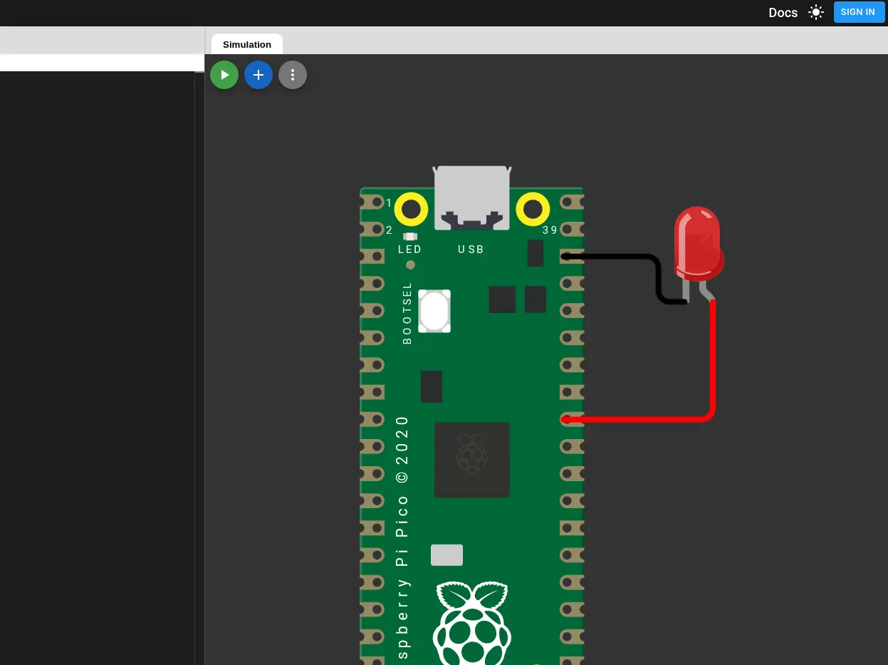
Now, with our LED correctly wired, and our script ready to go: click the green arrow button in the micro-controller screen to run your program. You might need to wait a bit if Wokwi´s servers are on some load. After this, you will be able to see your LED blinking.

Embedded Programming for my Final Project
I decided to make a prototype of some of my final project´s functionalities using Wokwi. In my Final Project Page I explain I want some play features in my robo-agent, including a motion sensor on top of the casing to simulate “petting” the robot. The robot will detect the signal and then trigger a motion in the tentacles servo motors. Doing this in Wokwi is pretty straight forward.
Note: For this sketch we´ll be using an ultra sonic sensor instad of the proposed capacitance sensor.
We´create a new project. We´ll be using the Pi Pico platform, but this time we´ll be using MicroPython. The reason behind this micro-controller + language decision is that I´m planning on using a Raspberry Pi 5 as the brain of my Final Project. Plus:
- All my scripting for the Final Project will be done in Python, meaning integration with the embedded programming aspect will be straight forward.
- The Raspberry Pi 5 has excellent integration with MicroPython (As well as all Raspberry Pi derivatives).
- There is no need no mix and match other micro-controllers in the mix. If by any chance this needed to be the case, this decision might change.
For these reasons, we´ll be creating a new blank Pi Pico + MicroPython project.
The Ultra Sonic Sensor
We´ll be using Wokwi´s ultrasonic sensor, a new component for us. This component requires 4 pin connections: VCC, Trig, Echo and GND. If we don´t know what these pins are meant to do, click the component. A question mark will appear on top of the component. Pressing it will open Wokwi´s documentation, where you can see what each pin is meant to do, plus a simple usage example:
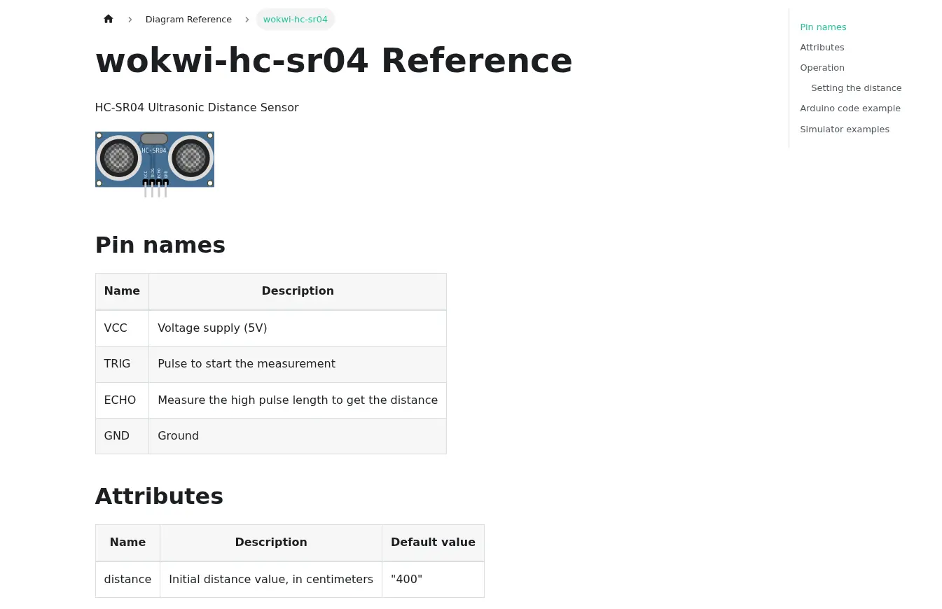
With this table and example, we know where our ultra sonic sensor must be connected:
- VCC into a 5v pin (VBUS or VSYNC)
- Trig into an OUT pin
- Echo into an IN pin
- GND to GNG
So, we can make the connections. We´ll also be adding an LED for later:
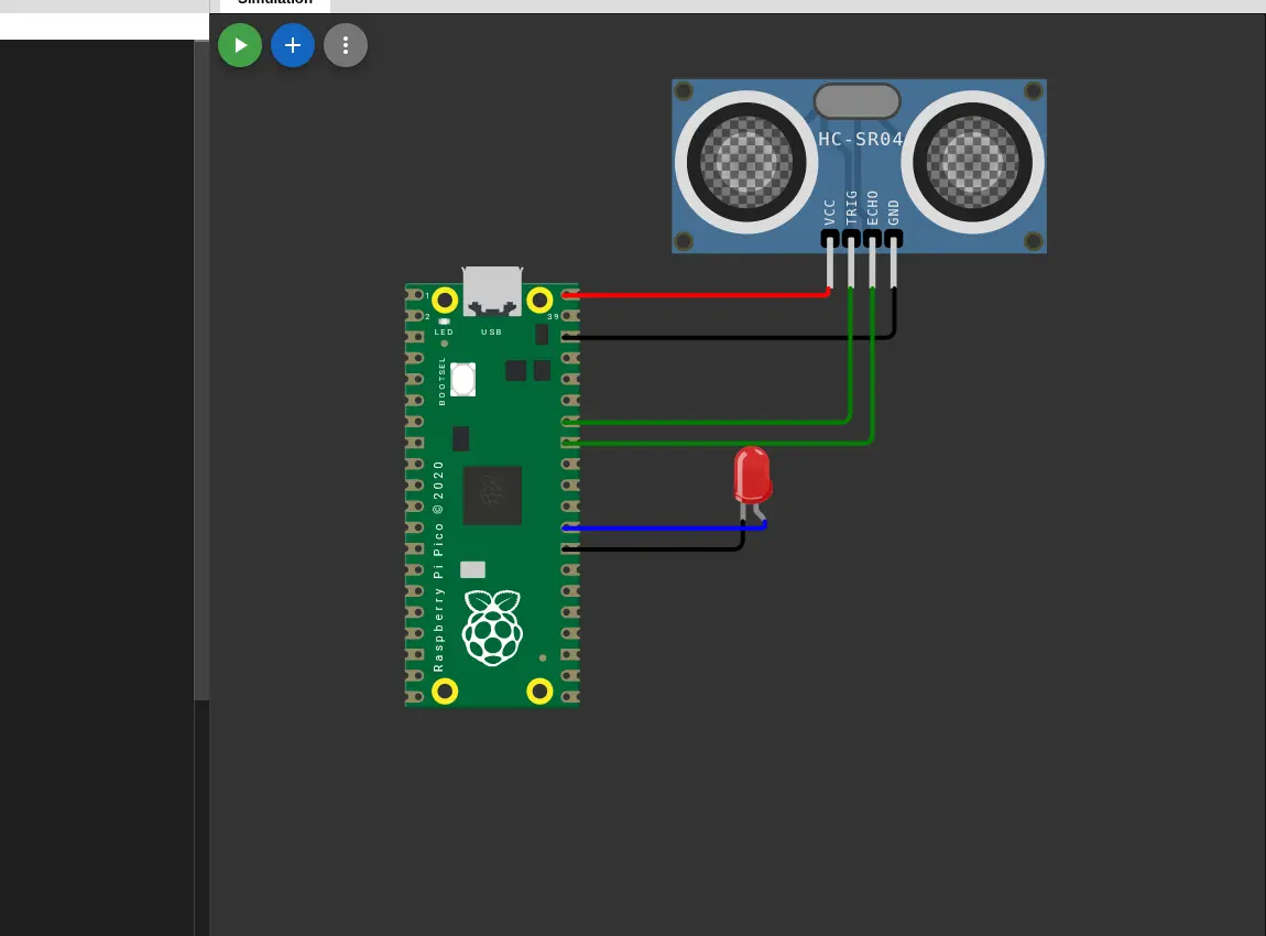
Now, using the example in our documentation, we can create our very own first script. This script will trigger the LED when a certain distance is met:
import time
        from machine import Pin
        time.sleep(0.1) # Waiting for the USB port to be ready

        # PIN Declatarion
        TRIG_PIN = 28
        ECHO_PIN = 27
        LED_PIN = 22

        # SetUp
        trig = Pin(TRIG_PIN, Pin.OUT)
        echo = Pin(ECHO_PIN, Pin.IN)

        led = Pin(LED_PIN, Pin.OUT)

        def motion_detected(treshold: int = 20) -> bool:
            trig.value(0)
            time.sleep_us(5)

            trig.value(1)
            time.sleep_us(10)
            trig.value(0)

            duration = machine.time_pulse_us(echo, 1)

            return duration / 58 < treshold


        while True:
            if motion_detected(100):
                led.value(1)

            else:
                led.value(0)

            time.sleep_us(10)
Here´s the code explanation:
def motiondetected()is a function that returns a Boolean value. If the distance calculated from the sensor (in cm) is less than a threshold (Given as an argument, 20 cm by default), the function returns True, else False.- In the main loop, if
motionDetected()returns True, the led value is changed to 1 (or HIGH), if not it is changed to 0 (LOW). It is the equivalent todigitalWrite()in Arduino.
Note: Your Python code does not have to look exactly the same as mine. Some extra lines where added, like
-> boolat the end ofdef motionDetected(), or:int = 20in(threshold: int = 20). This extra lines are good Python practices meant to make self documented, readable and stricter code.
The Servo Motor
Now it is time to add some Servo motors to the mix. Adding servo motors requieres another importation from the “machine” library calla “PWM”. Now we can declare our servo and create a function to move it:
servo = PWM(Pin(SERVO_PIN))
        servo.freq(50)
        max_duty = 7864
        min_duty = 1802


        def move_servo() -> None:
            servo.duty_u16(max_duty)
            time.sleep(0.3)
            servo.duty_u16(min_duty)
            time.sleep(0.3)
Here´s the code explanation:
- The servo is declared using the PWM library.
- The “Duty” values refer to the max and min range of movement of the servo motor.
- As the Project´s servos only need to go up and down without and specified range, we can just make it so that our servo goes up and down real fast.
Now it only takes linking some more servos in series to make the full arrange of tentacles.
What Comes Next?
With these new knowledge of embedded programming, we can start planning the rest of our Final Project´s requirements. Some of them include:
- An LCD screen control for facial expressions displaying.
- A Microphone array to detect sound and convert speech to text
- A Speaker module to reproduce the agent´s answers.
All of these functionalities can be implemented using MicroPython + the Raspberry Pi 5. Designing these features will requiere physical modules and testing to get write, something that Wokwi itself cannot give us. In the next weeks of this FAB Academy, the opportunity to work with real components will present itself. in the mean time, we can keep on experimenting with Wokwi and MicroPython.