This week's challenge was to design and fabricate something "big" using a CNC router. The focus was on understanding the workflow from 2D/3D design to G-code generation, considering tool diameters, joint types, and material safety.
Group Assignment
Testing runout, alignment, speeds, feeds, and toolpath marks for the CNC machine.
DesignAuto Cad
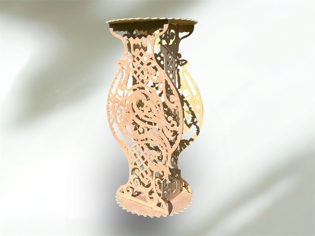
For this project, I designed a nightstand. The process involves creating 2D vectors or 3D models and then defining how the spindle will move to cut the material.
Vector Planning
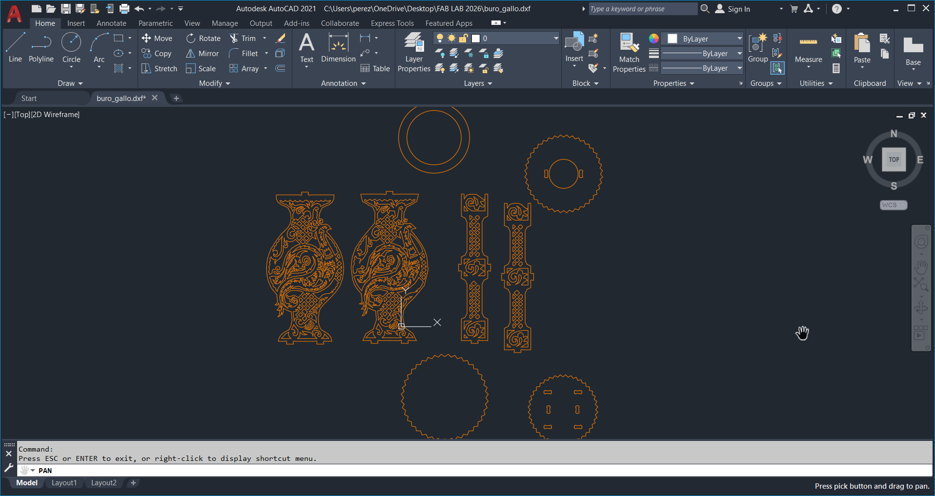
I used AutoCAD to develop the detailed plan of a small bureau intended for my room, integrating an ornamental design inspired by peacock
VCarve Pro Environment Setup
For the configuration of the file, we will export the design in DXF format. Once imported in VCarve Pro, we will adjust the dimensions of the work area to match the actual measurements of the triplay sheet.
Project Parameters
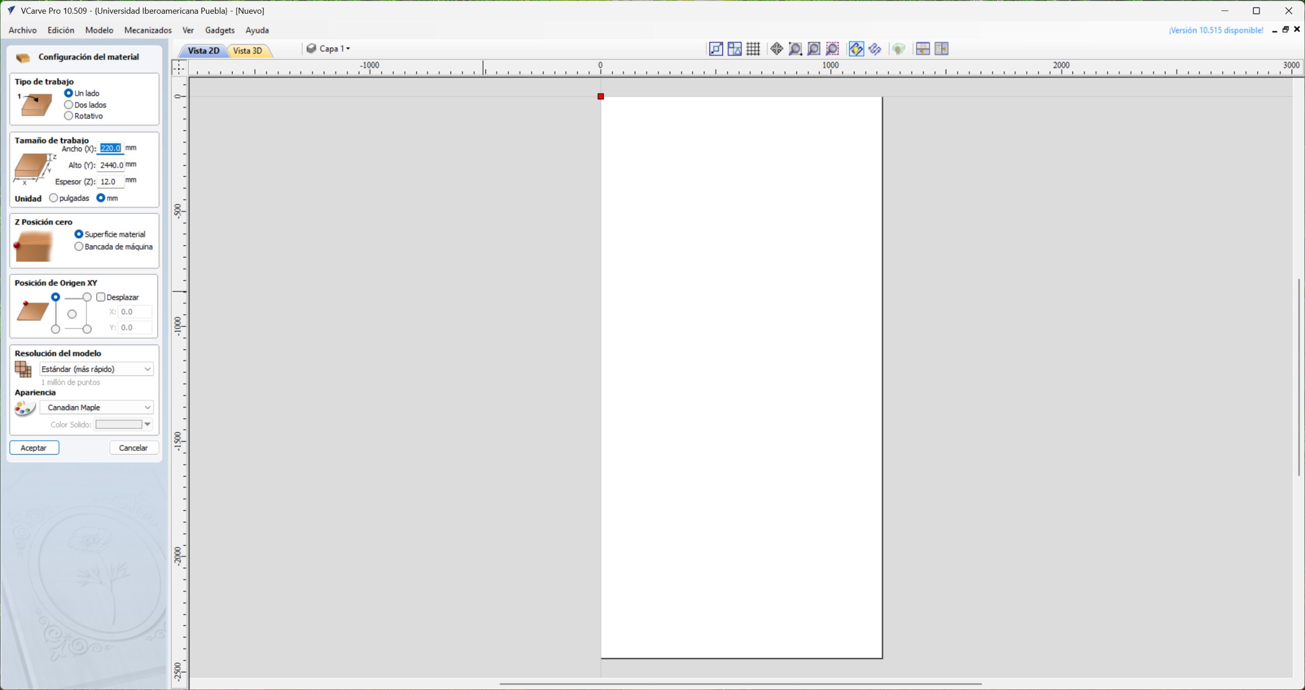
When creating the new file, initial project parameters are defined. In the Type of work section, I selected the 'Single side' option, as the design only requires machining on the upper side of the material. Afterwards, I configured the dimensions of the work area to match those of the triplay sheet (1220 X 2440 mm). The Z-Zero position was set on the material surface to ensure cutting accuracy before confirming changes.
Vector Importing and Part Layout Strategy
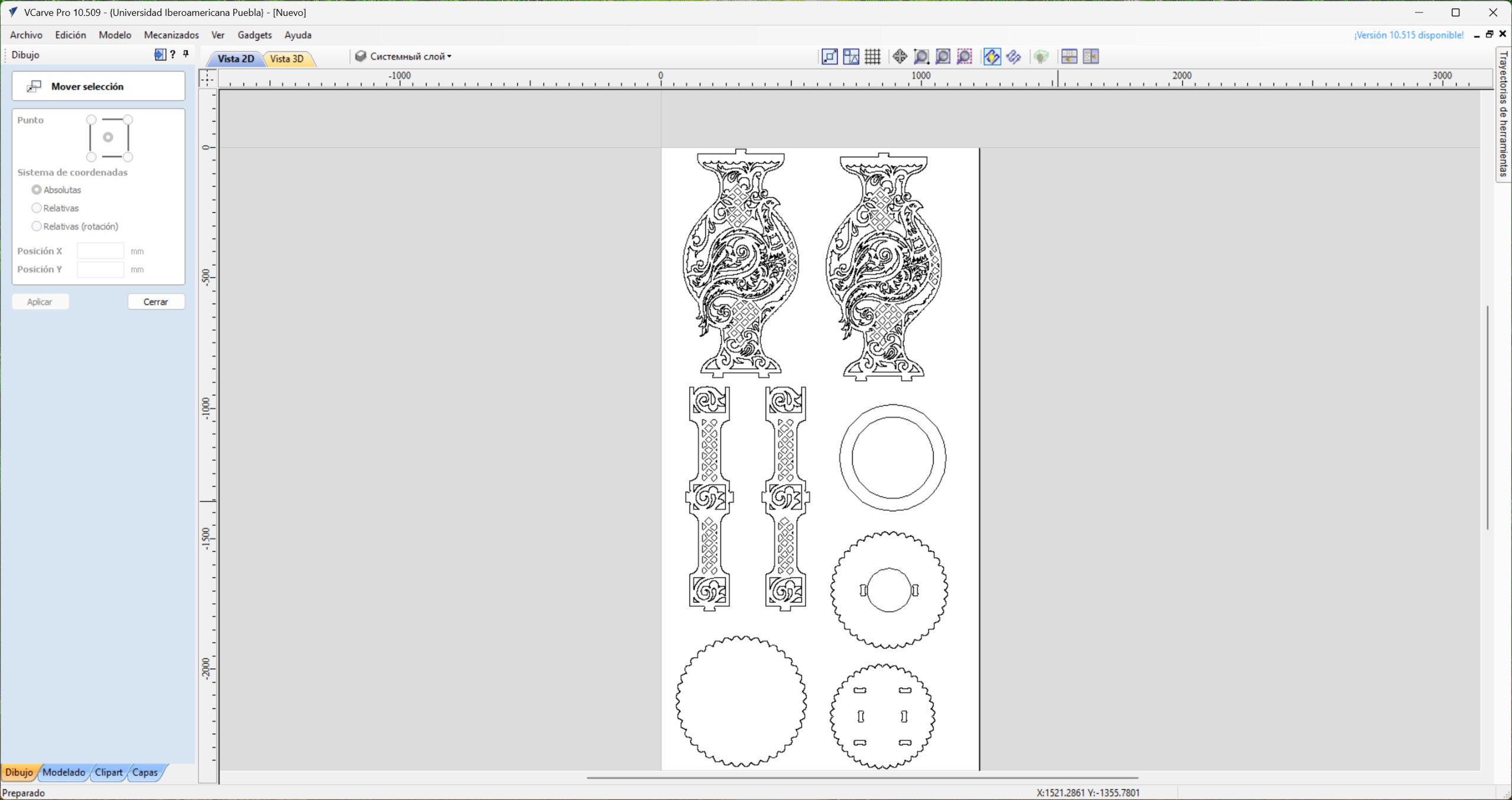
Once the environment is set up, we import the DXF file into the workspace. The fitting of the parts was carried out in order to optimize the material; for this, a perimeter margin of 20 mm was respected throughout the triplay sheet, thus ensuring a safe and efficient cutting area.
2D Profile Strategy & Over-Cut Calibration
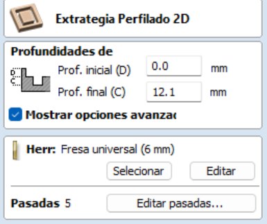
In the 2D profiling strategy, we set a final cutting depth of 12.1 mm. This value was defined slightly higher than the nominal thickness of the material to ensure total detachment of the parts. To optimize machining time, 3 passes were established, determining that a larger number would be redundant given the simple geometry of vectors and tool capabilities.
Tool Selection
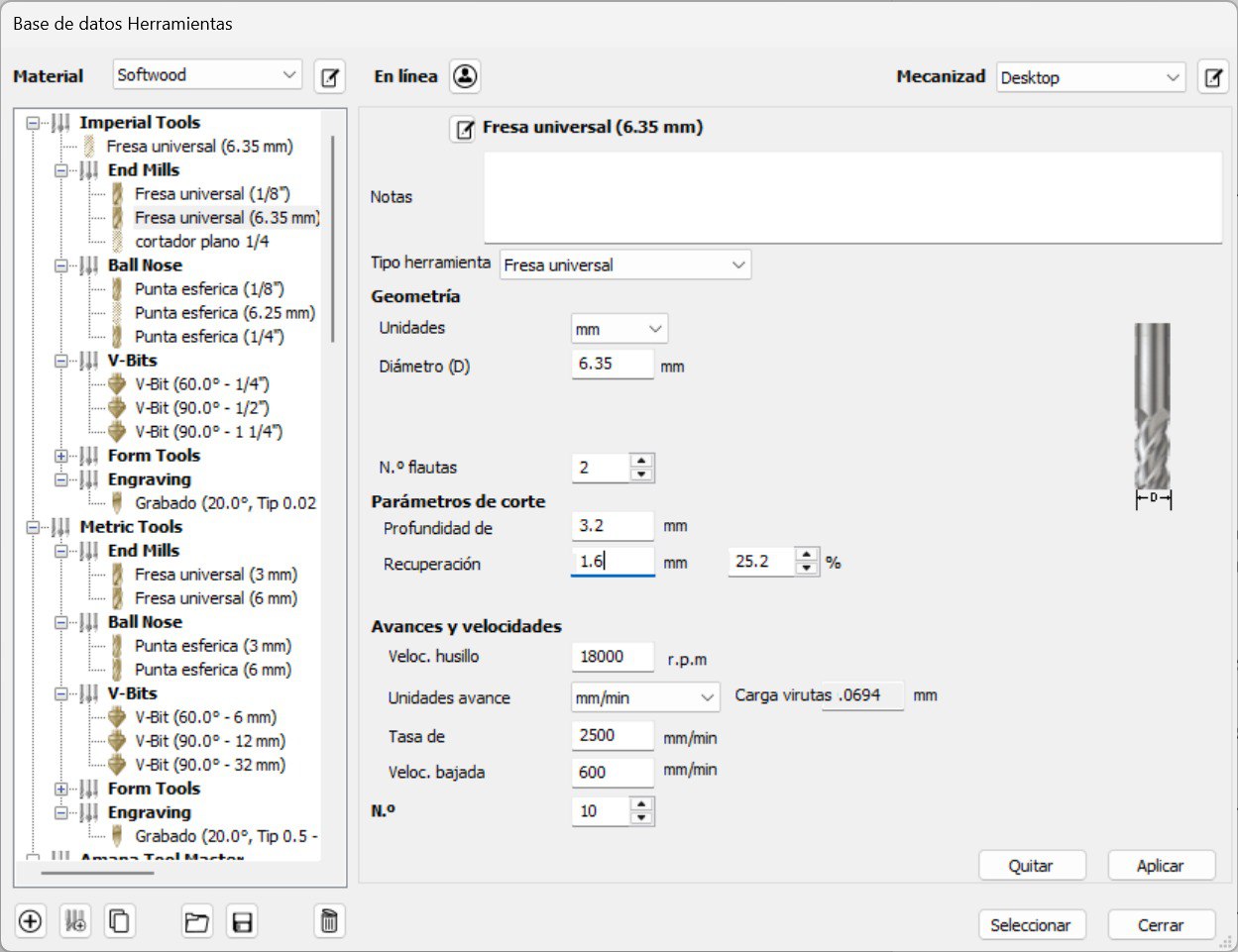
For the tool setup, a 1/4" (6.35 mm) cutter was selected from two flutes. The cutting parameters were established in the metric system, defining a spindle speed of 18,000 RPM and a plunge rate of 600 mm/min, ensuring a constant and safe advance for the material.
Kinematic Entry
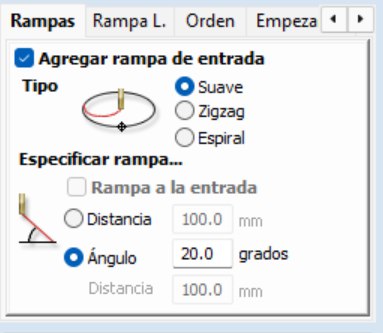
In the configuration of the trajectories, the entry ramps were enabled with a smooth profile and a 20° angle. This helical or angle-in technique prevents material damage by preventing the tool from exerting excessive vertical pressure when starting cutting.
Visual Simulation & G-Code Export
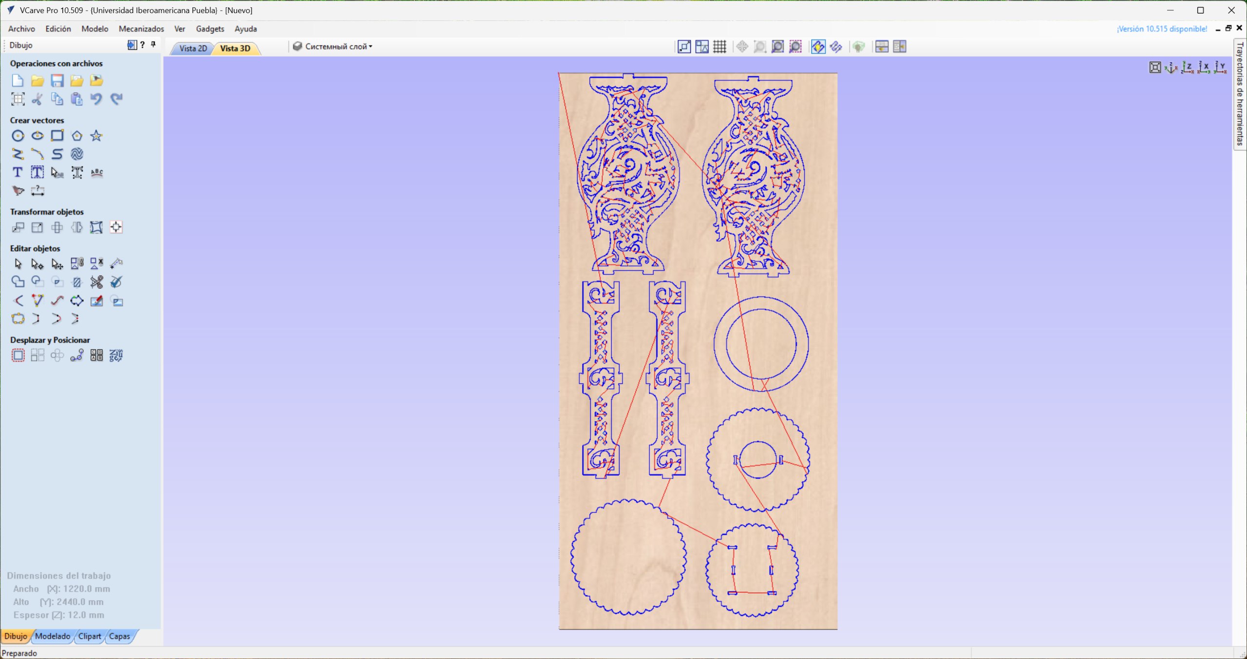
In the preview, the path of the tool is observed, where the entry points (plunge), the direction of machining progress and the end point of the operation are clearly identified. Finally, we exported the G code using the appropriate post-processor for Mach3/4. The resulting file is saved in format . tap (or .txt), which contains all the coordinate and speed instructions necessary for the CNC to execute the project.
Health and Safety
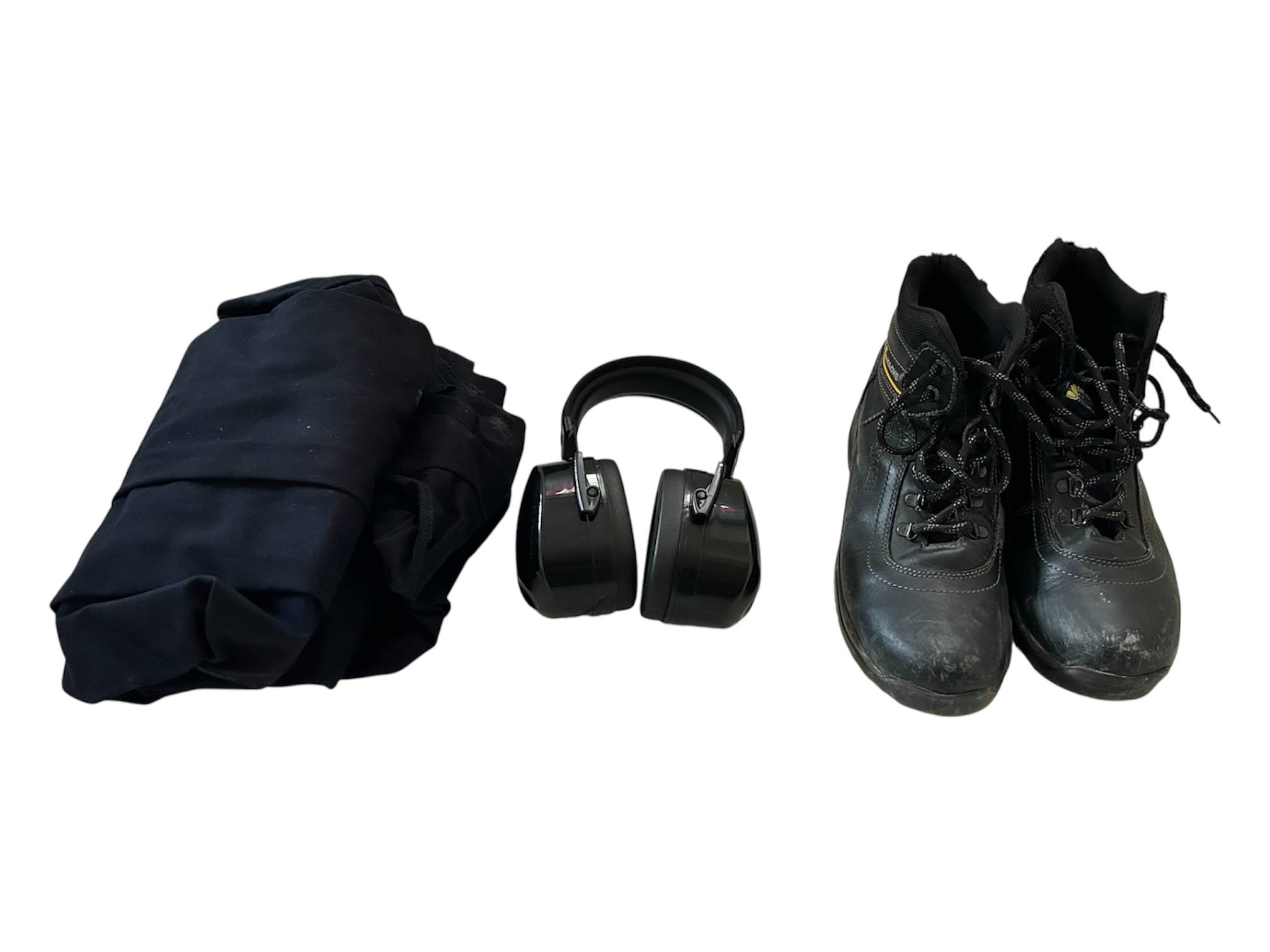
Use of the CNC machine strictly requires proper personal protective equipment. This includes safety footwear (industrial boots), work overalls and certified hearing protection, necessary to mitigate the high sound pressure levels generated during the machining process.
Machine Specifications
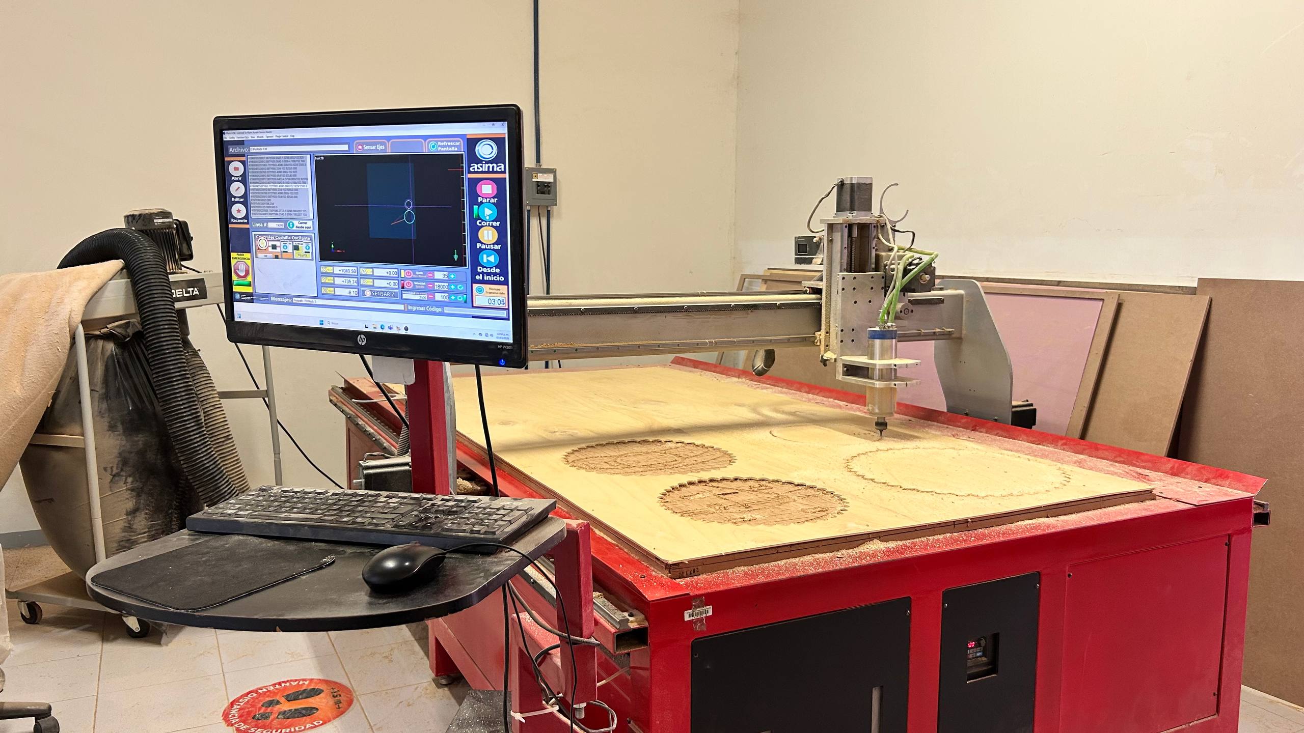
The equipment used is an Asima brand CNC operated under the Mach3 control interface. The laboratory has a dedicated workstation where cutting files are uploaded and final configuration adjustments are made before starting the machining cycle
Startup
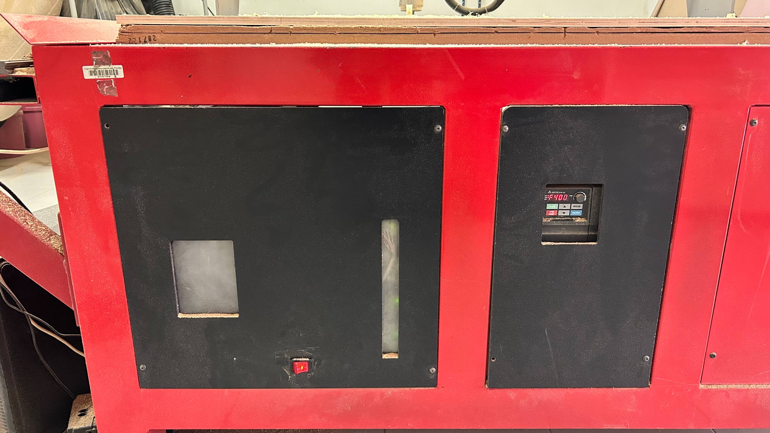
For the start of the Asima CNC, the main switch located on the lower panel must be activated. The dashboard has additional controls that are set by default; these should not be manipulated unless a collision occurs or the tool gets stuck, which would require a system restart or an emergency stop.
Waste Management & Extraction Protocols
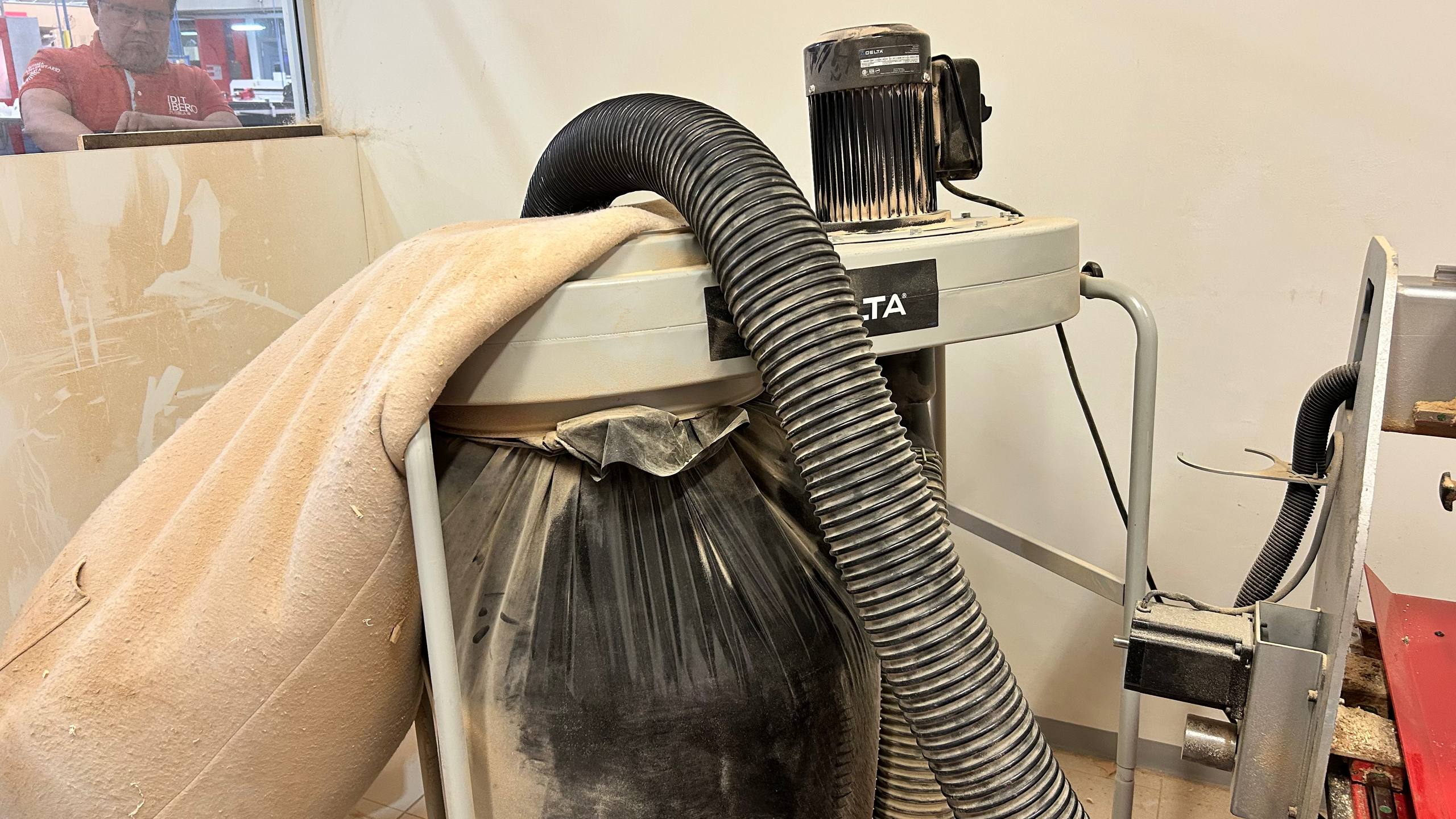
The work area is equipped with an industrial extraction system for waste management. It is imperative to vacuum the slaughter table before fixing the material and perform a deep cleaning at the end of the process. By safety protocol, it is strictly forbidden to vacuum manually during machining, due to the risk posed by the moving axes and the movement of the tool
Machine Calibration and Work Home Establishment
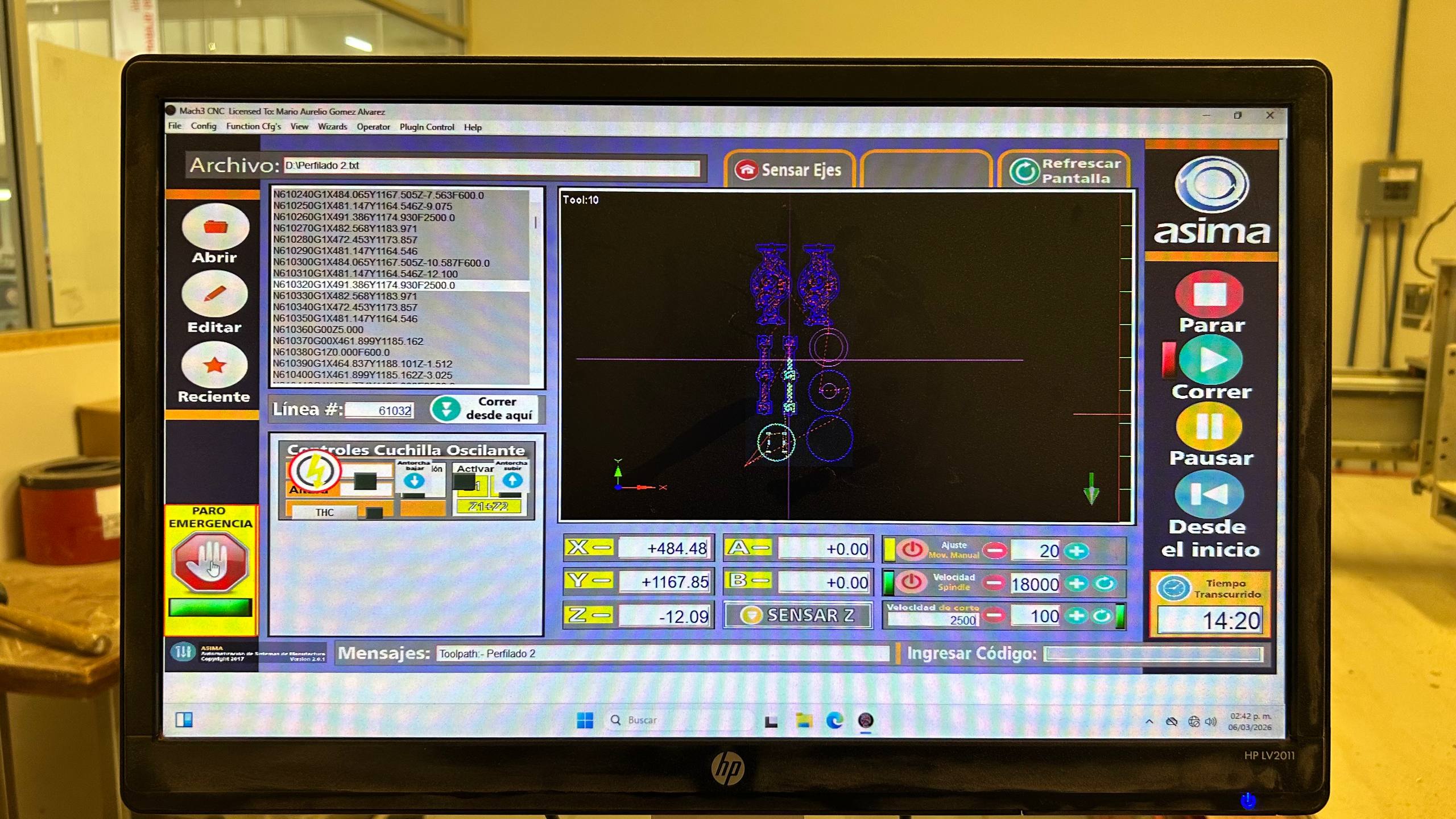
We started the Mach3 CNC interface to import the G code ( .txt file). The software generates a preview of the integrated cutting paths in the work area. Subsequently, we manually move the axes using the control (jog) to place the tool at the lower left vertex of the triplay. Once this point is defined as our origin (Home), we reset the coordinates to zero on the X, Y and Z axes. Finally, we validate that the spindle speed is 18,000 RPM and execute the cutting cycle (Cycle Start)
Technical Incident
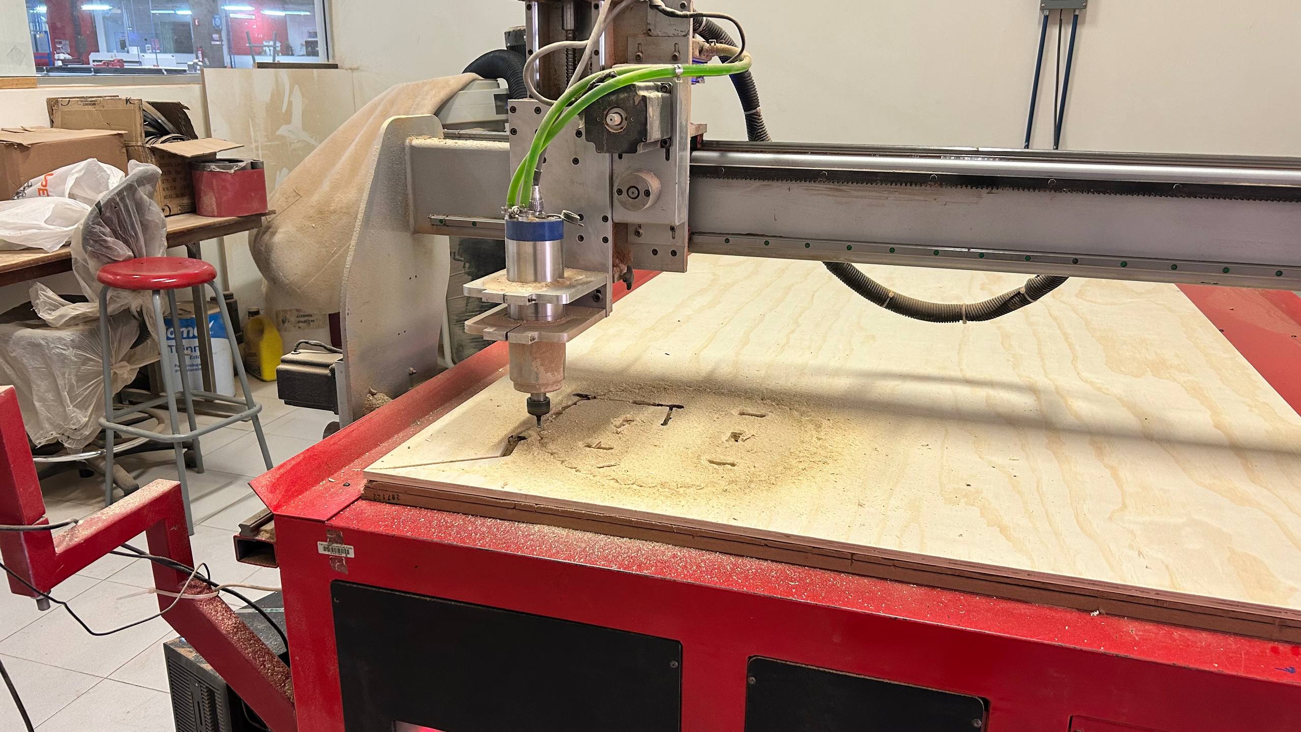
Due to setbacks with the original material supply (12 mm), a last-minute change was made to a 6 mm triplay. By skipping the update of thickness parameters in the software, the tool ran paths with excessive depth. This caused the millstone to not rise sufficiently above the new surface during the transition movements, causing unwanted cuts and displacement marks on the material.
Clearance Plane Conflict & Z-Gap Analysis
In the first operations it is observed that, although the profiling was correct, there is an obvious error in the safety height (Z-gap). Not being configured for the new material thickness, the tool did not retract sufficiently, executing a cutting path during the transition movement to the next part.
Self-Correction Analysis
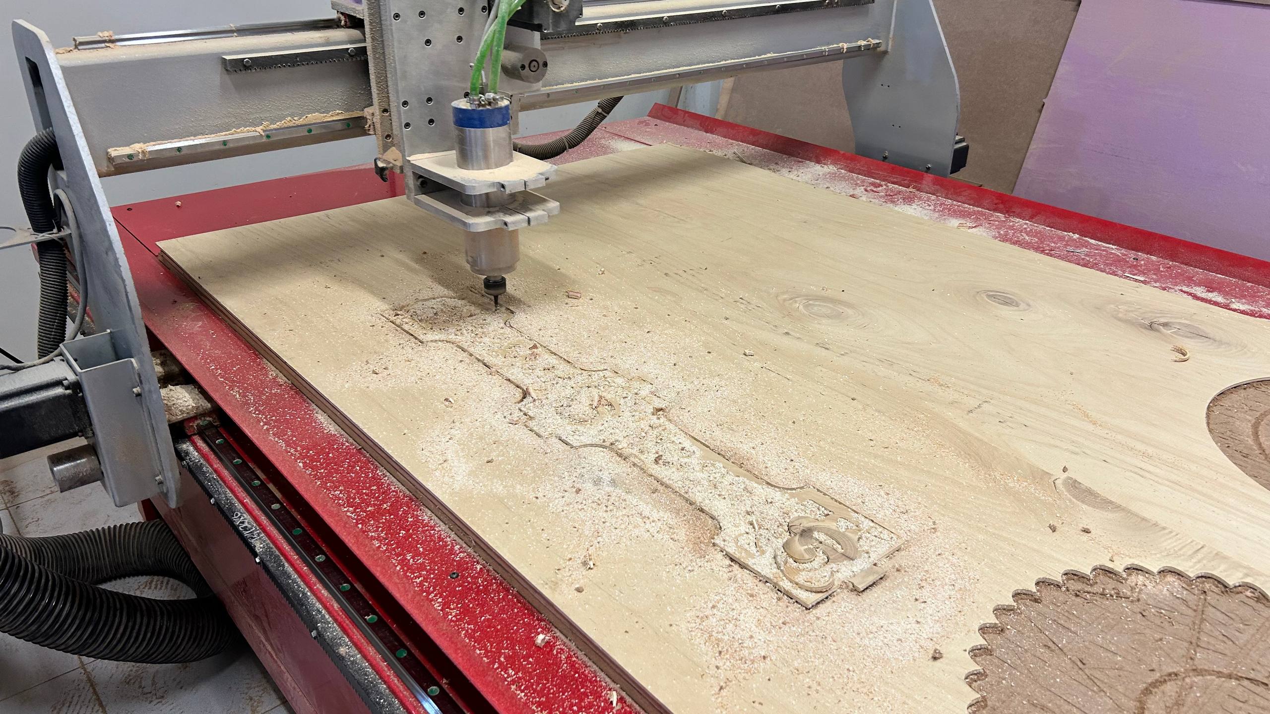
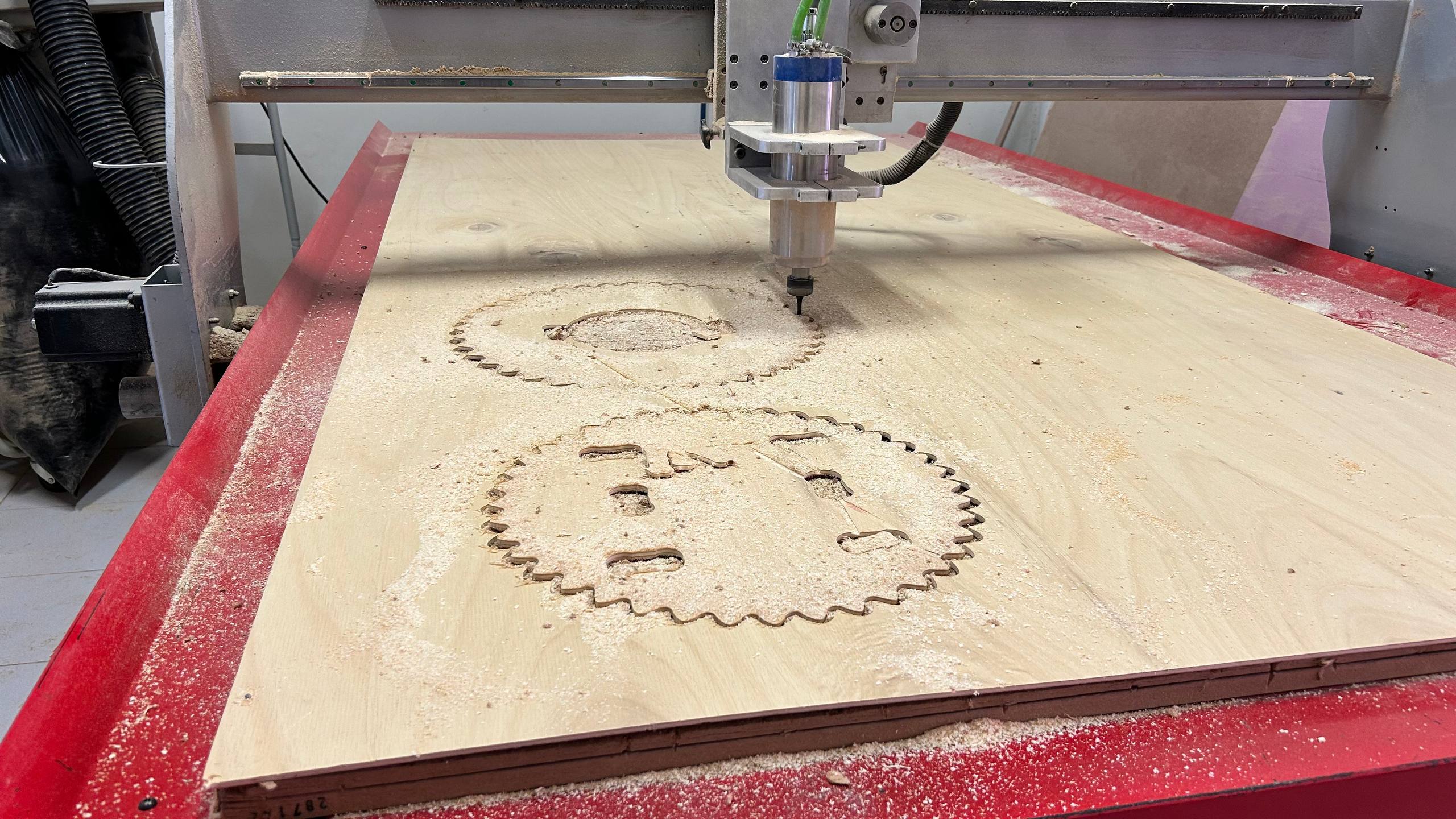
From the third and fourth cuts, the incidence of depth disappeared. The initial error was probably due to a flap in the perimeter area of the triplay, which altered the actual distance from the configured Z-Zero. Once the tool advanced to areas with greater flatness, machining normalized.
Post-Machining Workflow
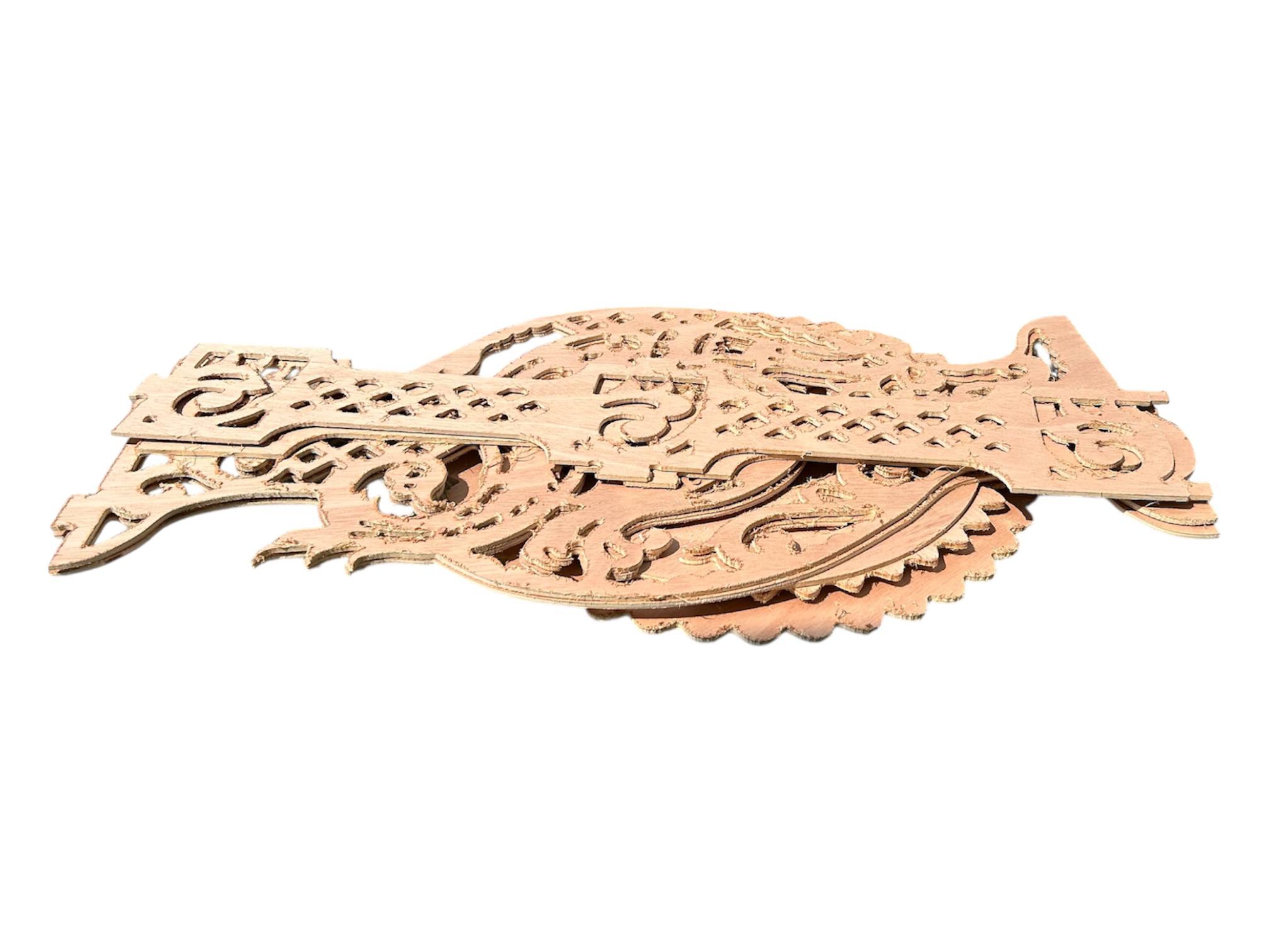
After the machining cycle, we proceeded to disassemble the parts and deep clean the work area. In the visual inspection of the components, the need for a post-processing (manual sanding) process was identified to remove sludge and smooth out the resulting edges from cutting.
Assembly and Finishing
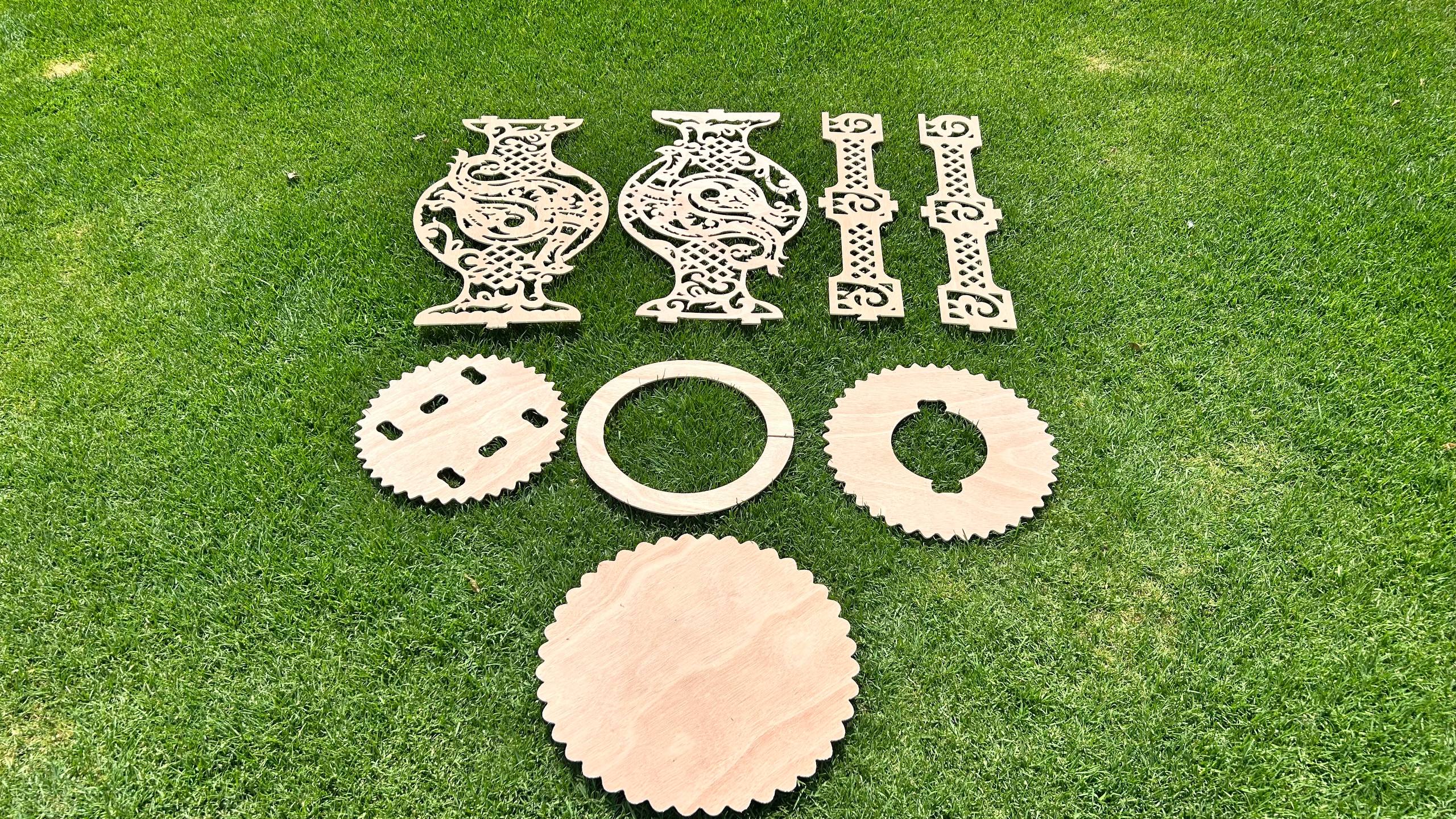
Once the cut was finished, I removed the tabs using a chisel and sanded the edges. The pieces fit together perfectly thanks to the tolerances and dog-bone joints designed earlier.
Final
Once the cut was finished, I removed the tabs using a chisel and sanded the edges. The pieces fit together perfectly thanks to the tolerances and dog-bone joints designed earlier.