This week's focus was on exploring two different cutting technologies: Laser Cutting and Vinyl Cutting. The main challenge was to design and fabricate a parametric construction kit, ensuring perfect fit (press-fit) by accounting for the material's kerf.
Group Assignment
Characterizing our laser cutter: kerf, power, and speed.
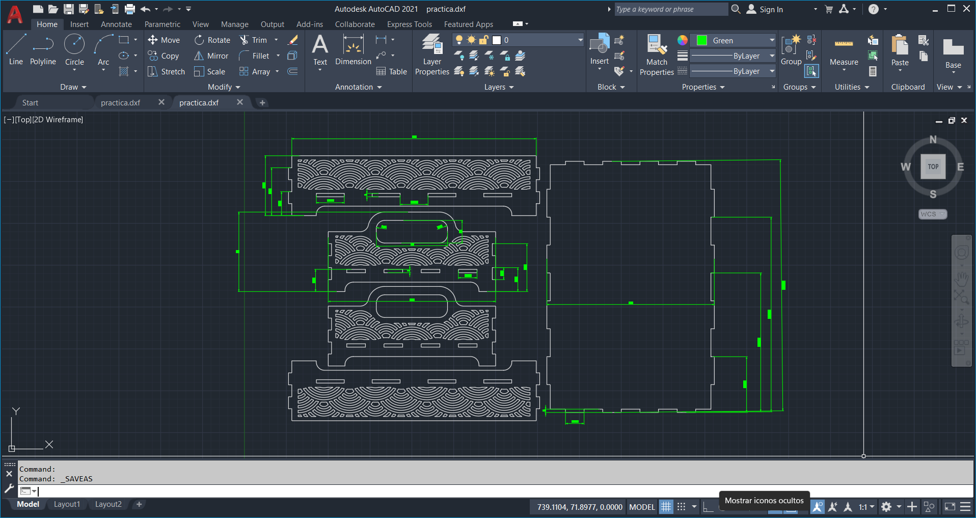
Auto Cad Parametric Design
Using AUto Cad, I designed a modular kit where the slots are defined by parameters. This allows the design to adapt automatically to different material thicknesses.
Enable parametric environment
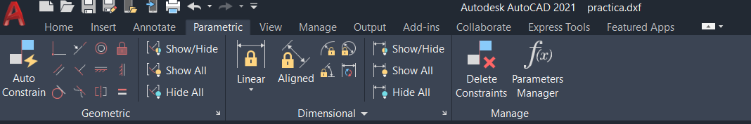
To move forward with the design control, lets go to the Parametric tab. Once there, we will find the essential tools to give intelligence to our strokes: Geometric: With them, we will define physical rules, ensuring that the lines are always kept parallel, perpendicular or joined to each other. Dimensional (Dimensional): Here we will set the exact measurements, controlling lengths and angles with total precision. Parameters Manager: Finally, lets use this panel to manage all our formulas and variables from one place, allowing global changes in an instant.
Applies geometric constraints ("smart" shape)
To give continuity to the style of collaborative guidance, we will use geometric constraints to define the logic of our drawing without having to resort to numbers yet. In this process, we will apply options such as Horizontal/Vertical to set orientations, Parallel/Perpendicular to establish relationships between lines, or Coincident to ensure that points and lines are held together; also, we will use Equal to equalize lengths and Tangent to smooth the contact between lines and arcs, simply by selecting the desired restriction icon and then objects to observe how small symbols appear that confirm the established relationship.
Manage parameters and formulas
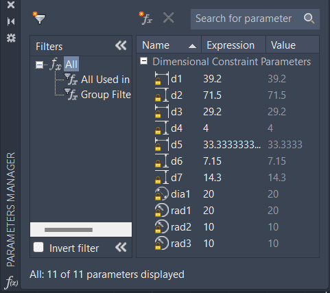
To close this process with full control, we will open the Parameters Manager, where we will view in order all the parametric dimensions of our project; from this panel, we will be able to change values quickly, create custom User Parameters and apply smart formulas such as radius = width / 4 or sseparation = high - 10, so that when you modify any parameter, the drawing is automatically updated reflecting the new calculations instantly.
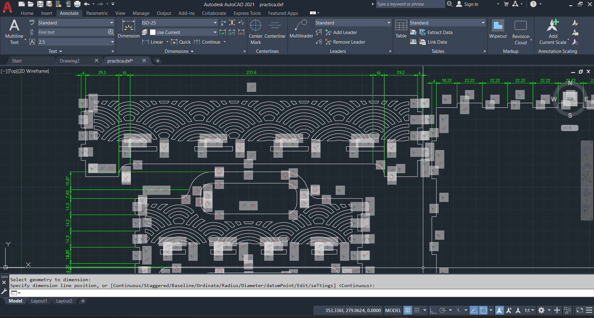
Parametric Constraints
To finish the workflow, once we have prepared our file, we will export it in DXF format so that the laser cutting machine can interpret the cutting paths correctly; also, lets note that, even if we choose to export in PDF format, the team is able to read vector information with equal accuracy, ensuring that our design is ready for physical production smoothly.
Smart Carve
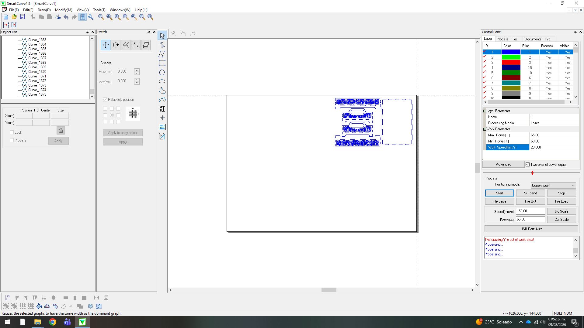
We export the design in DXF format and load it into the SmartCarve software of the laser cutter. Once imported, we set the cutting parameters with a maximum power of 65%, a minimum power of 60% and a feed speed of 25 mm/s.
Laser Cutting Machine
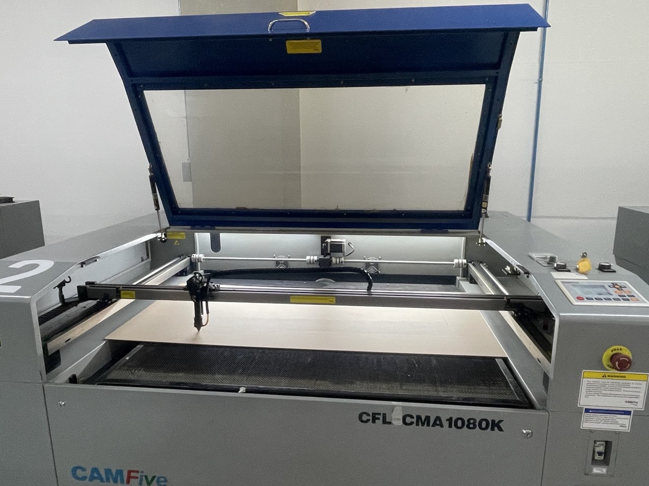
After activating the 'Go Scale' function to verify that the design is within the working area, we close the machine cover for safety. Once validated, we start the process with the 'Start' button, at which point the laser head will begin cutting the material.
Cutting Quality
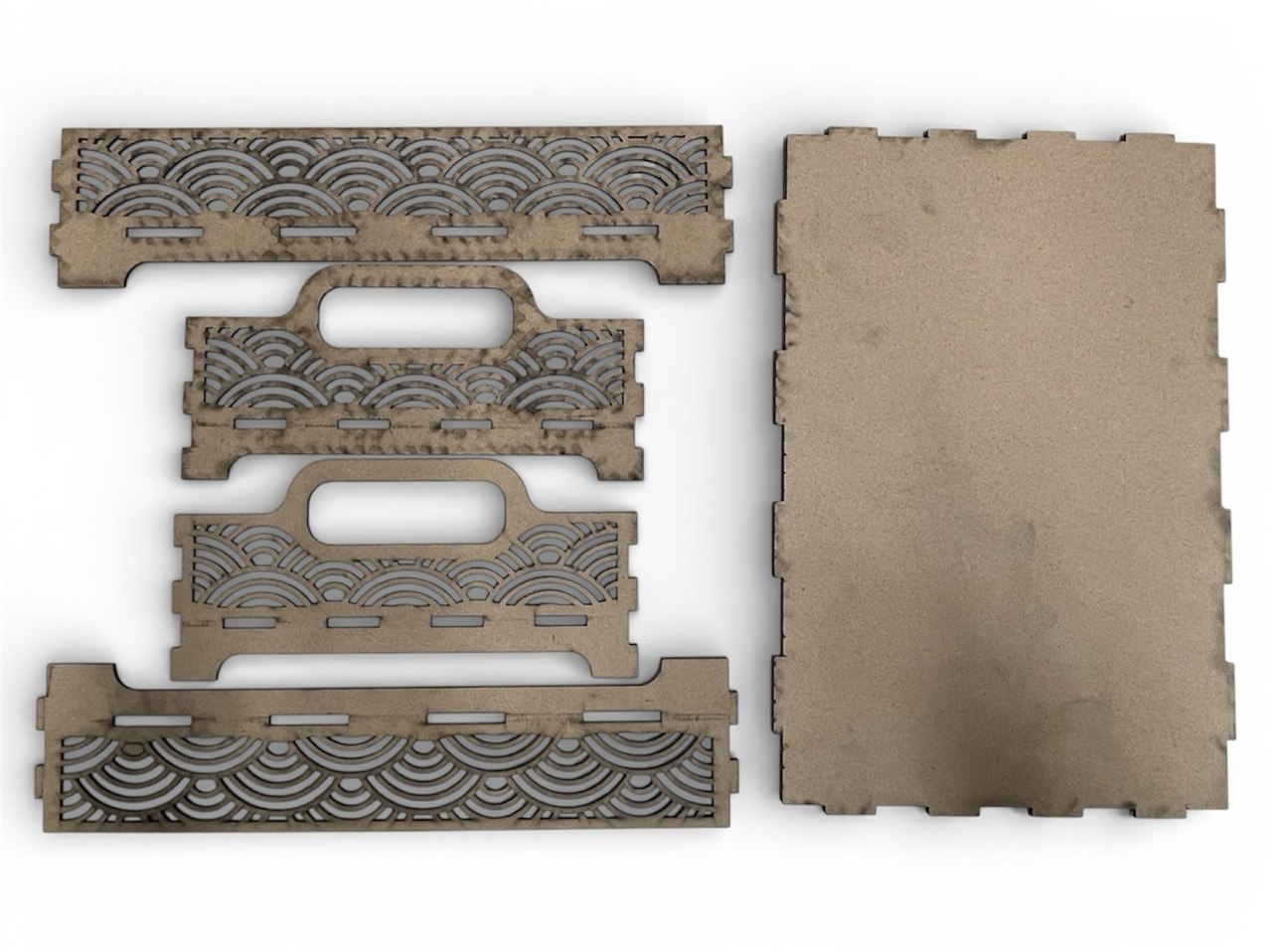
At the end of the process, we remove the MDF sheet and validate that the parts are easily detached; this confirms that the selected parameters were correct. It is important to note that these values vary depending on the machine, the cleaning of the optics and the focal length between the nozzle and the material.
Final Results
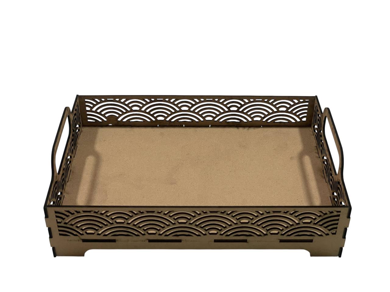
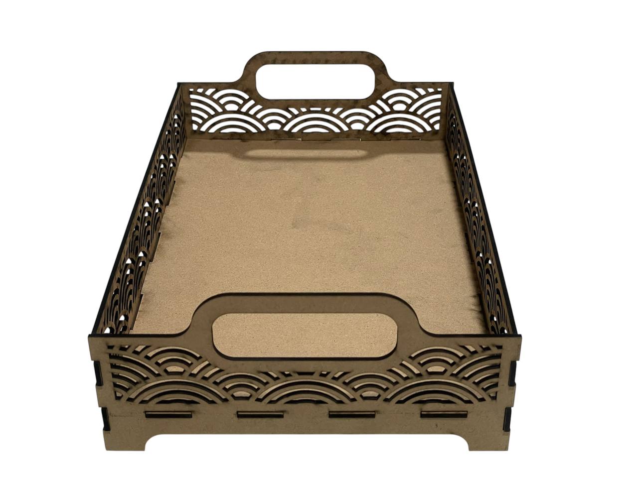
Finally, we assembled the components. During this stage, I identified a 3 mm discrepancy due to an imprecise calculation of tolerances. Despite this margin of error, the structure maintains its mechanical integrity and manages to hold up, although it underlines the importance of adjusting the fit parameters in future prototypes.
Vinyl Cutting Vector Graphics
For the vinyl cutter, I focused on creating a high-detail decal. The process involves preparing a vector file and managing the blade force settings.
Vectorization & Cleaning
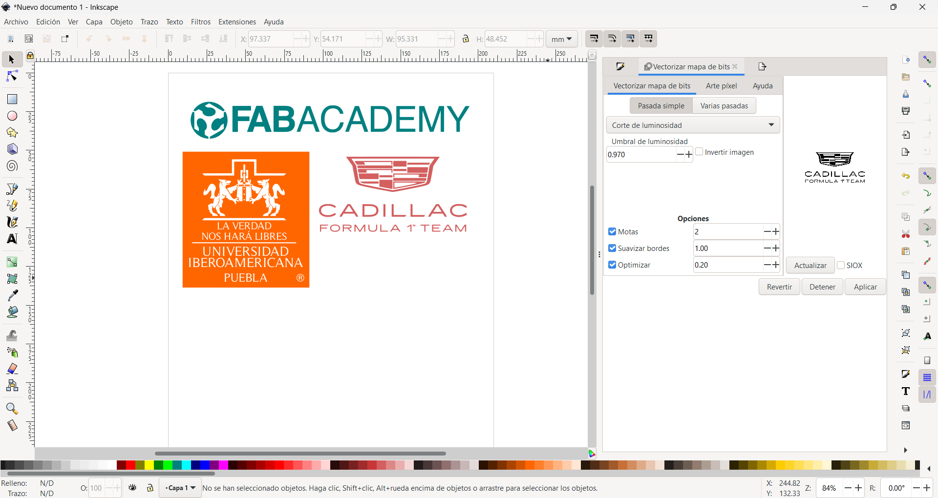
I used Inkscape to trace a bitmap image. It's crucial to have closed paths and no overlapping lines to ensure the cutter doesn't tear the material.
Prepare Files
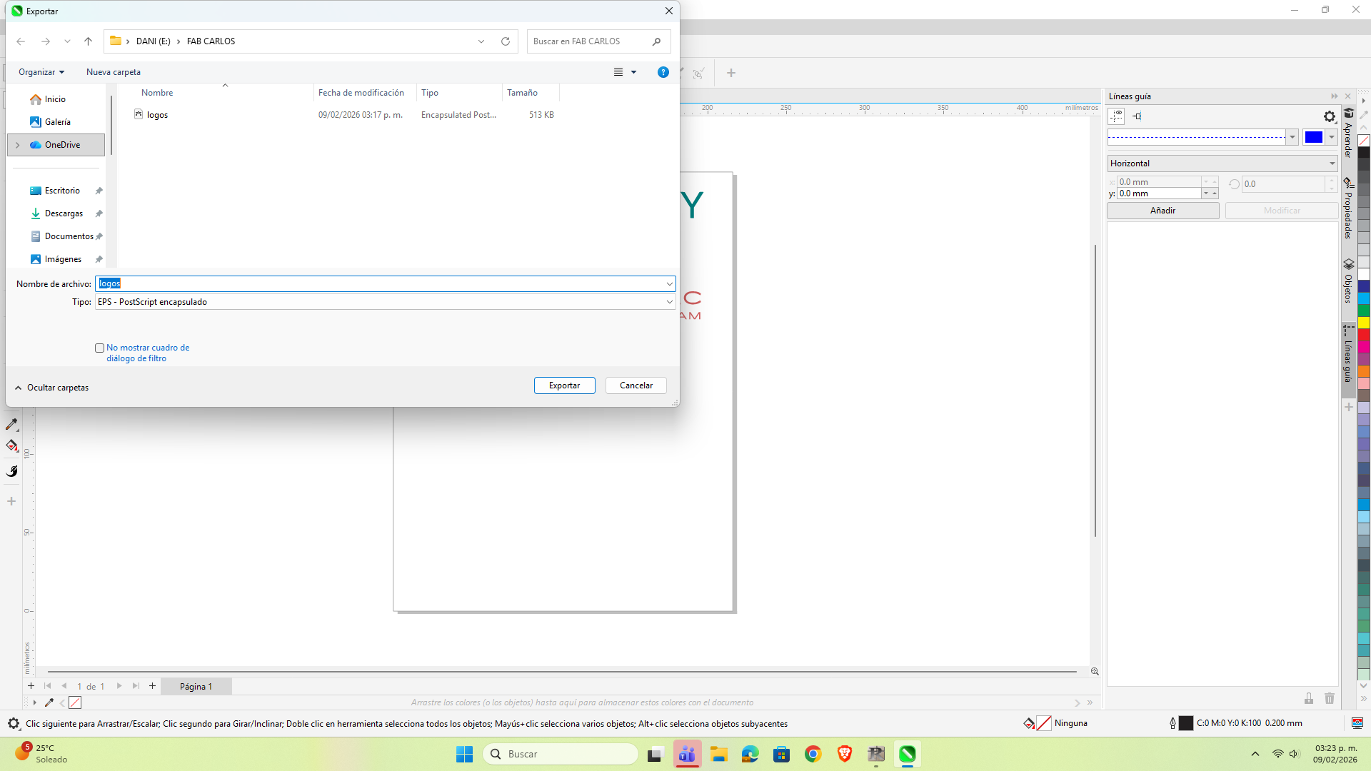
To work with the Roland vinyl cutter, I first opened the design in CorelDraw. Subsequently, I exported the file in EPS format, thus ensuring vector compatibility with machine cutting software.
Import Files
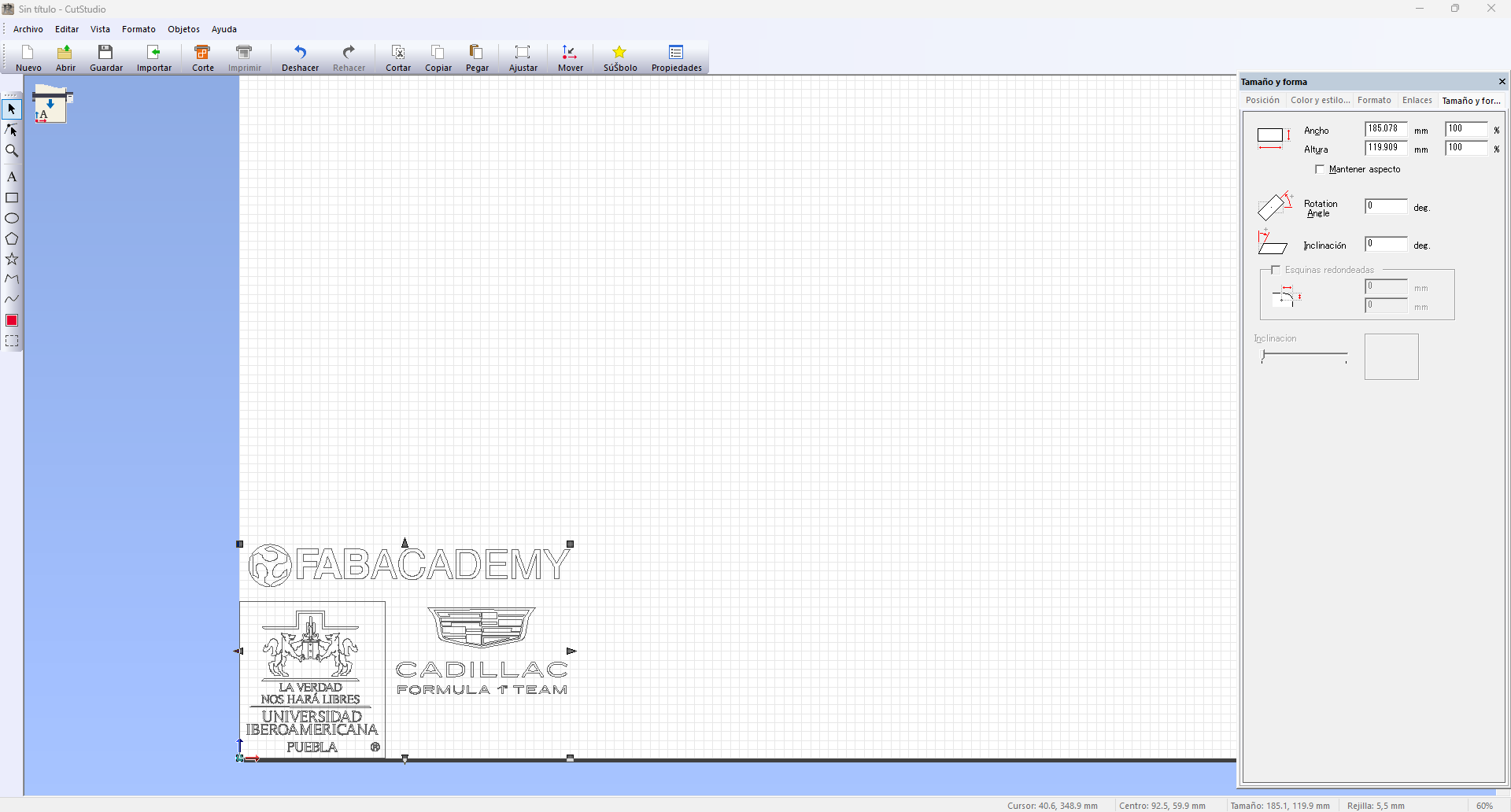
We import the file in EPS format into CutStudio software. Once loaded, we perform a visual inspection to verify that the nodes and plots were transferred correctly and that the scale matches the original design.
Settings
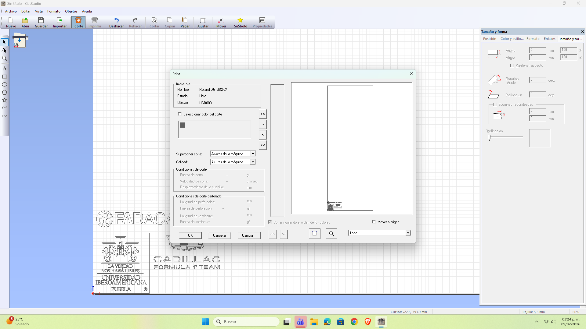
Once the design has been validated, we access the cutting configuration window. At this stage, we keep the preset parameters and confirm the operation by clicking on 'OK' to send the file to the plotter.
Plotter Settings
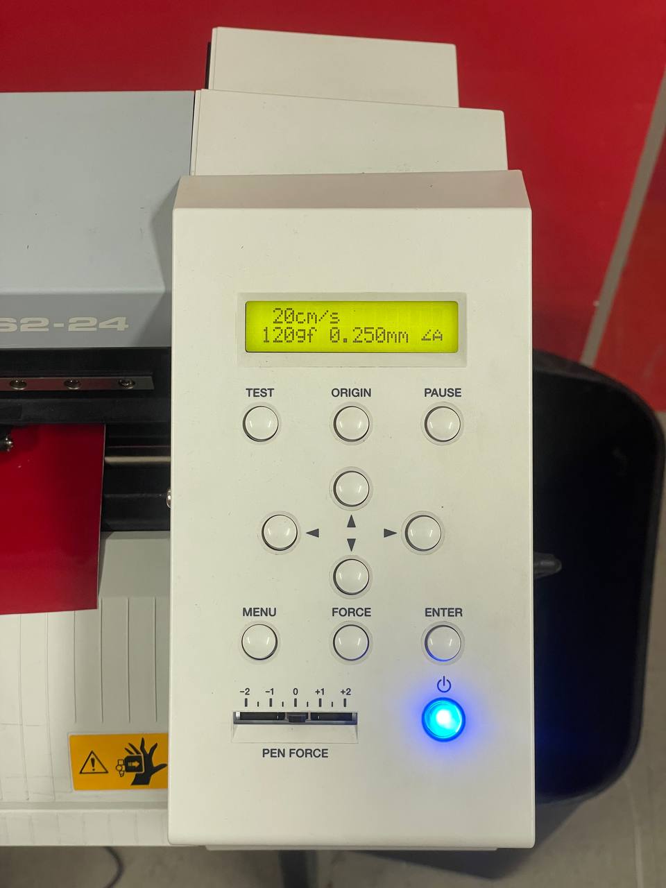
We turn on the cutting plotter and press 'Enter' to initialize the equipment. When the system requests to define the dimensions of the material, we select the option 'Piece' (piece); the machine will automatically scan to determine the available cutting area before starting the process.
Plotter in Action
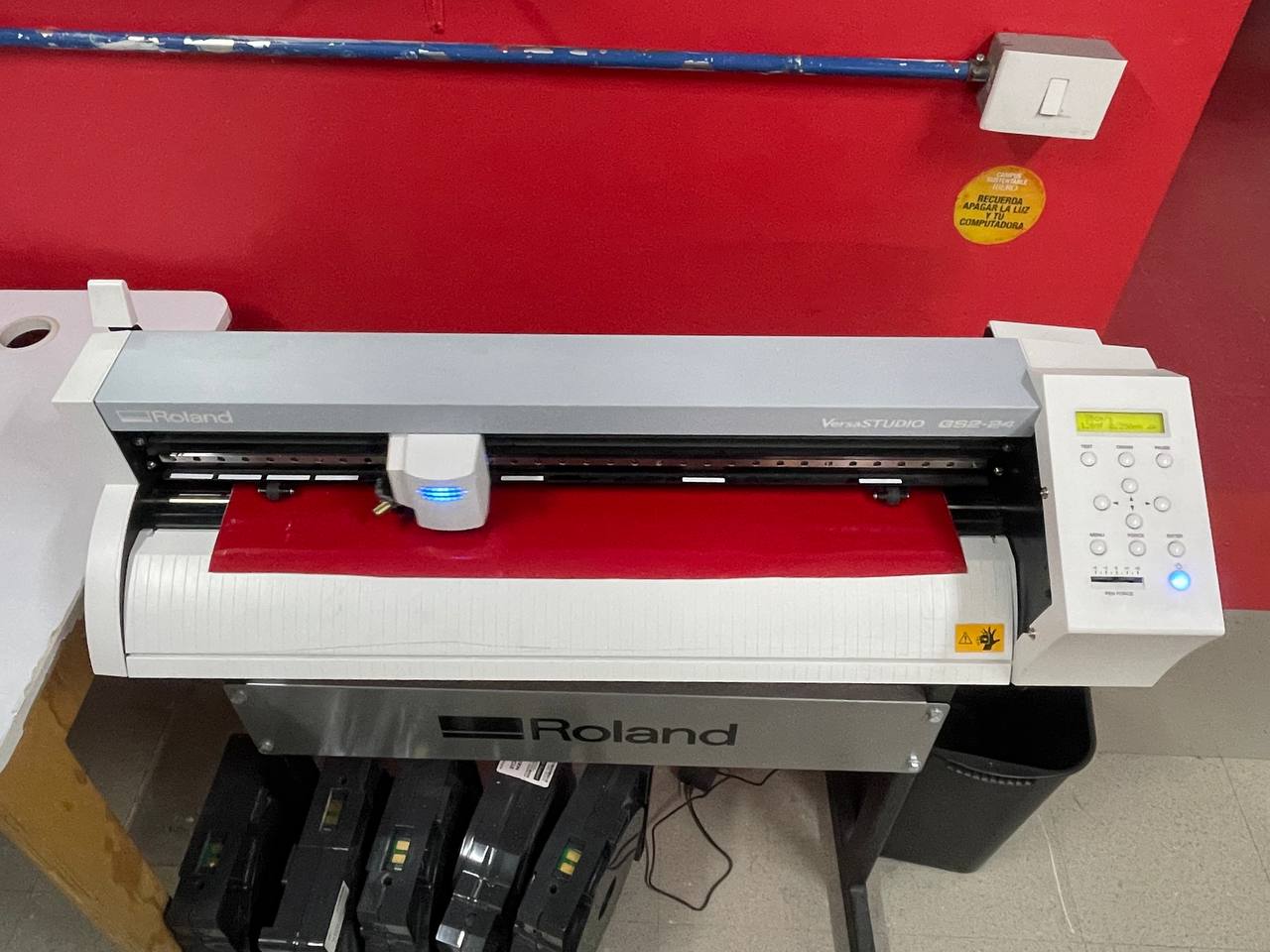
At the end of the cut, the head will automatically return to its point of origin. We press 'Enter' to release the roller, remove the clamping clamps to extract the material and finally proceed to turn off the equipment.
Final Results
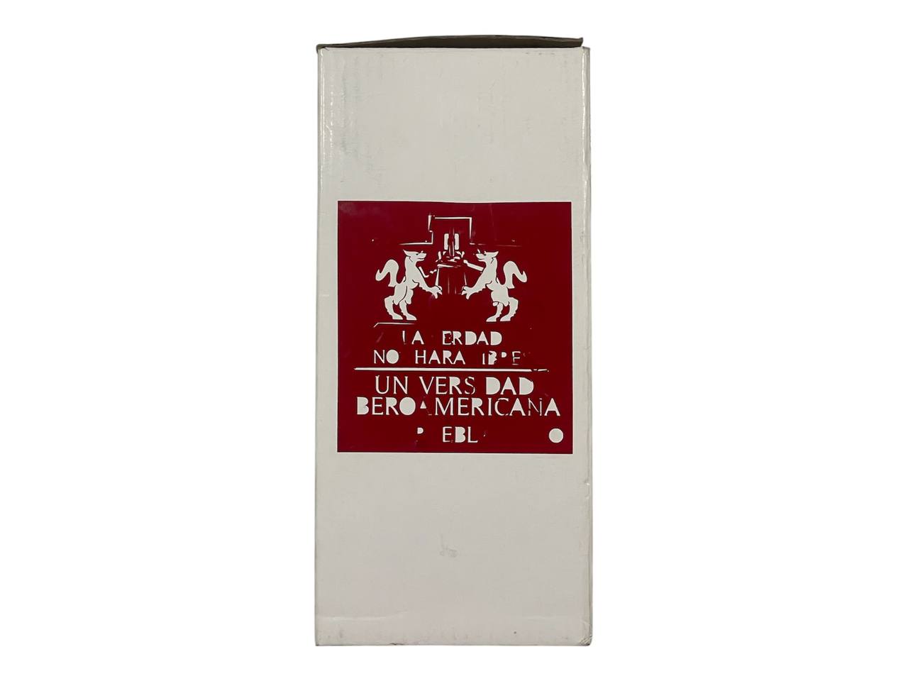
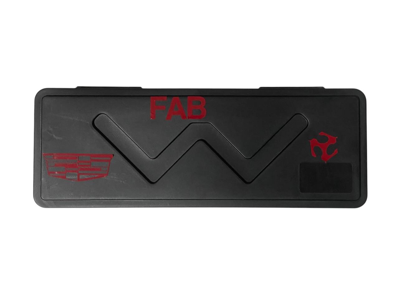
After waxing the vinyl to remove excess material, I proceeded to the application of the designs. I chose surfaces for everyday use in the laboratory, such as my digital vernier and the packaging of a thermos; in this way, these objects remain as a constant reminder of my passage through the Fab Academy.