The objective for this week was to design a 3D mold, machine it in wax, and use it to create a flexible mold for casting final parts. I explored the transition from digital geometry to physical volume using subtractive and additive processes.
Group Assignment
Reviewing safety data sheets for molding and casting materials and making test casts with different materials.
Design & Machining WorkflowSolid Edge
The process began with the 3D modeling of the positive piece, followed by the generation of the negative mold box and the toolpath calculation for the CNC router.
3D Modeling (Positive & Negative)
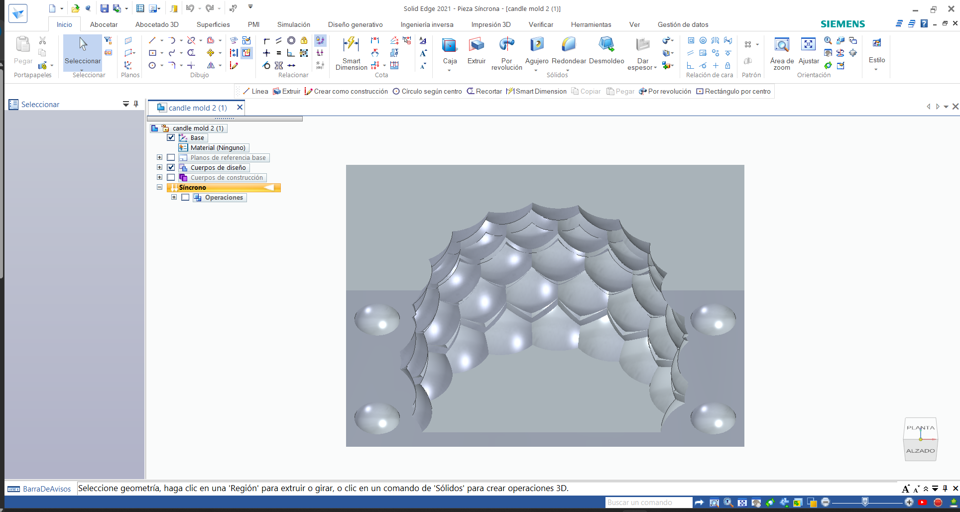
The design of the masterpiece was born from exploring organic patterns and their interaction with light. The main goal was to create a textured surface that would challenge the limits of conventional unmoulding. Using Solid Edge, I parameterized the geometry to ensure a smooth transition between cavities. A critical aspect of the process was the integration of draft angles in each relief; this technical detail not only defines the visual aesthetics, but also ensures that the piece can be removed from the silicone mold without damaging the fine details. Finally, I designed the exact sized cast container to optimize the use of molding material.
Slicing Strategy
Once the design was finished, he exported the components to the Ultimaker Cura laminating software. To ensure that the inner texture is true to the digital model, I set up a thin layer height to capture the complexity of the organic facets. The approach here shifted from subtraction (CNC) to addition: I optimized the infill density to give the mold structural integrity without wasting material, and selected a printing orientation that minimized the need for internal supports, thus protecting the surface finish of the cavities where the wax will be poured.
Structural Integrity & Surface Resolution
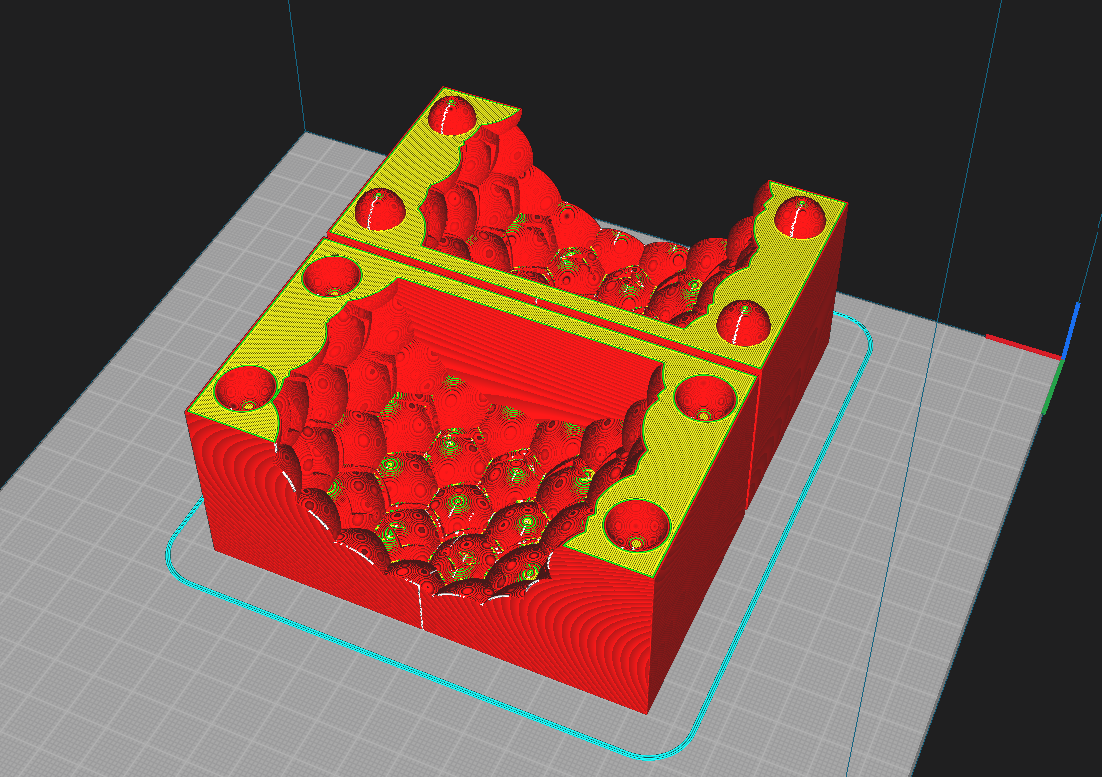
The configuration in the laminator focused on ensuring mold integrity during spillage. I selected a layer height of 0.2 mm to balance the production time with sufficient resolution for organic geometries. The decision to use 4 upper and lower layers together with a 20% cubic infill responds to the need to create a rigid structure capable of withstanding the pressure of the casting material without deforming. In addition, I maintained a temperature of 200°C to ensure optimal layer adhesion, eliminating porosity that could filter the liquid from the mold.
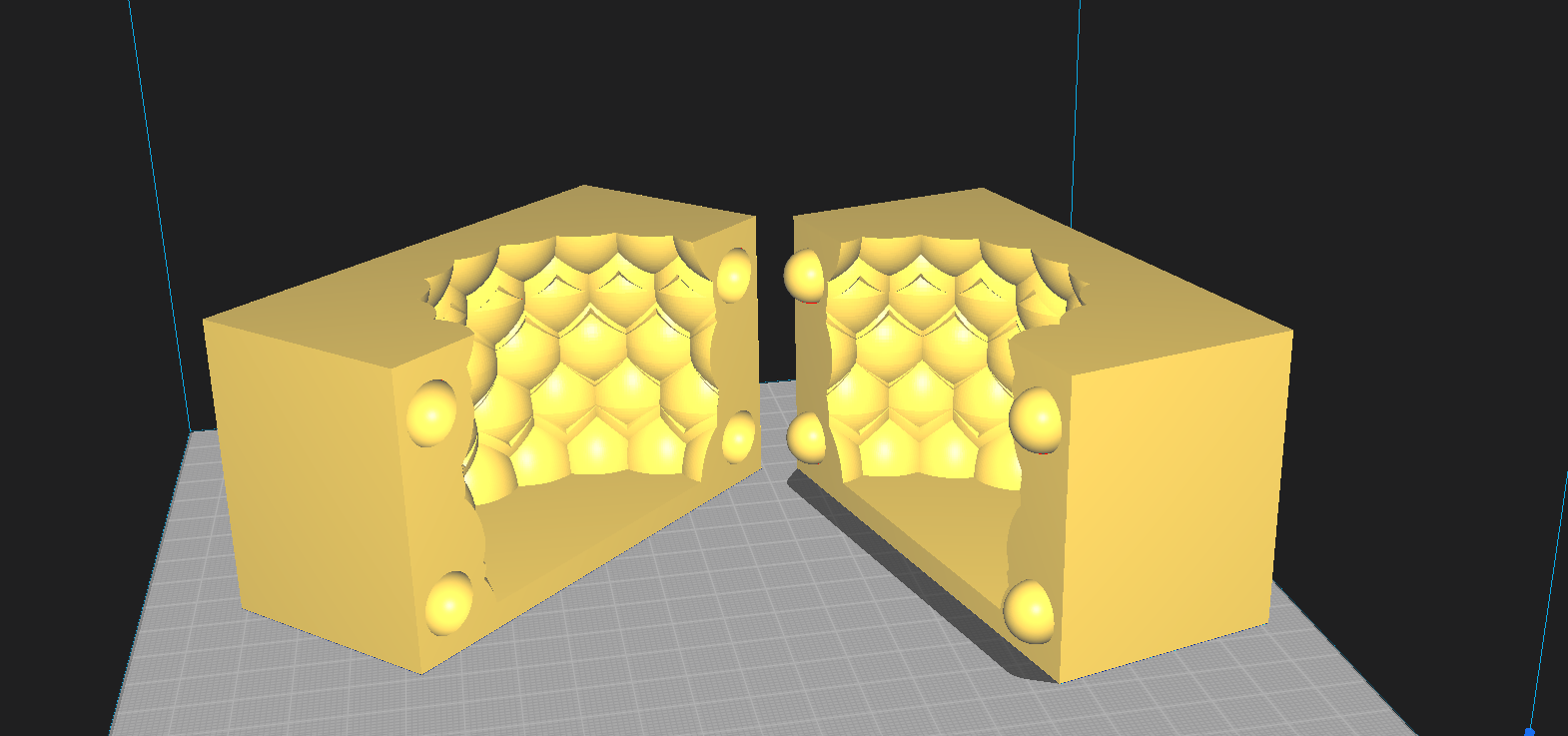
Post-Print Inspection
After completing the printing cycle, the result is these two masterpieces with a translucent finish that allows you to visually verify the homogeneity of the internal walls. At this stage, I performed an assembly test to validate that the tolerances designed in CAD work correctly in reality; the registration pins ensure a tight closure, eliminating any possibility of misalignment or "step" on the final part. This level of accuracy is crucial to ensure that, when pouring the silicone, the mold captures the exact geometry without any leaks.
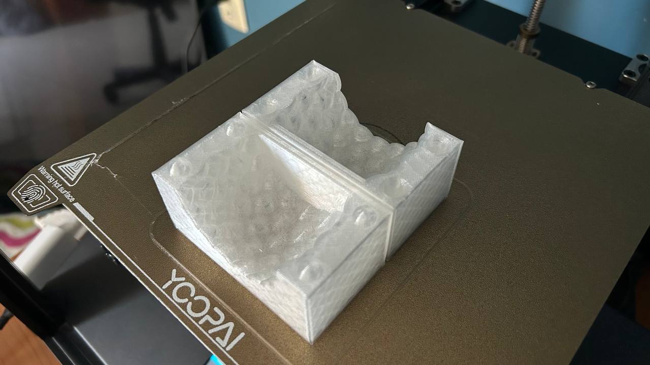
Mitigating Thermal Risks
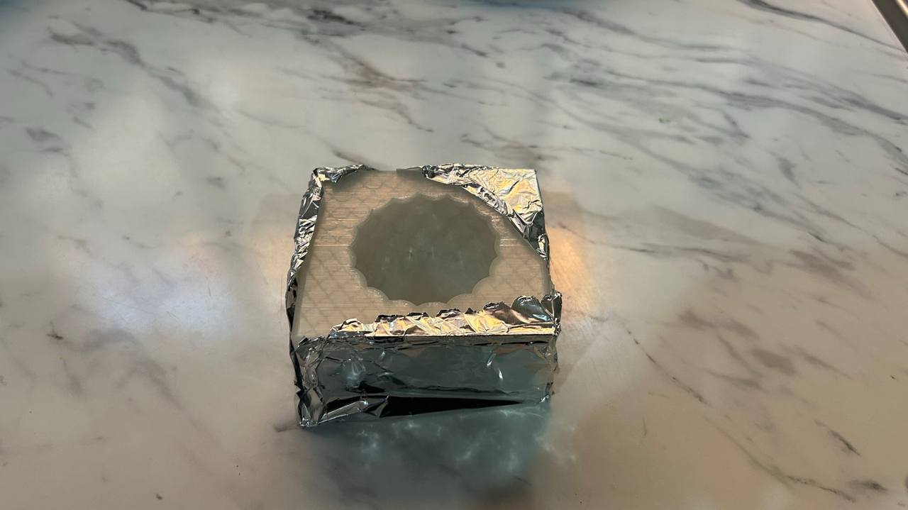
During the paraffin pouring phase, I implemented a protective barrier using aluminum foil around the mold container. This preventive measure was taken to mitigate the risk of accidental leakage during high temperature dumping. By securing the perimeter, I not only ensure a clean and efficient work area, but also facilitate material recovery in case of overflow, maintaining the integrity of the work surfaces and optimizing the flow of the post-manufacturing process.
Casting Execution
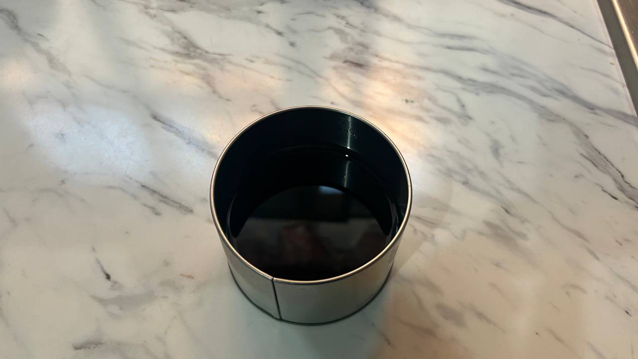
Once the mold was stabilized, I proceeded to prepare the paraffin. This step required precise temperature control to ensure optimal viscosity that allowed the material to flow into the deeper details of the geometric pattern. The mixture was pigmented to achieve a deep opacity, designed to highlight the shadows of the faceted relief. When carrying out the discharge, the key was to maintain a constant and controlled flow, minimizing the introduction of air bubbles and ensuring uniform heat distribution to avoid irregular thermal contractions during cooling.
Controlled Solidification
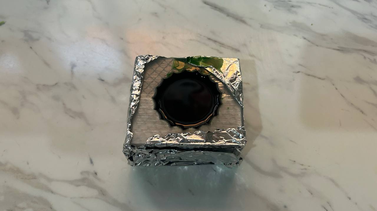
After the paraffin was poured, the mold remained at rest for approximately 4 hours. This waiting period is critical to allow for gradual solidification from the core towards the outer walls. Being a geometry with thickness variations, accelerated cooling could cause contractions (crunches) or internal cracks that would ruin the faceted pattern. Patience at this stage ensures that the molecular structure of the material is stabilized, resulting in a piece with uniform density and a perfectly smooth surface at the time of unmolding.
Demolding Analysis
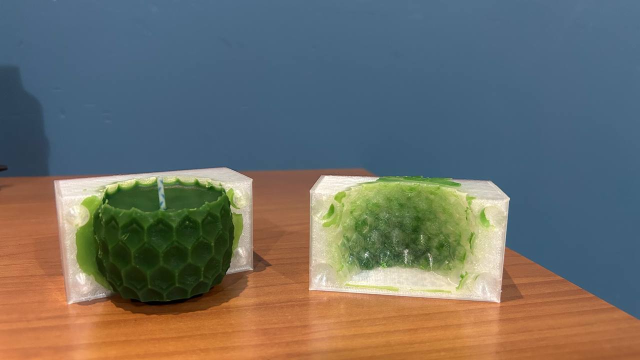
After the solidification period, I proceeded to open the mold. The result is a piece that successfully transposes parametric geometry from the digital environment to the physical. The panal texture was replicated clearly, validating that the CAD designed exit angles were sufficient to prevent the material from tearing. Technical analysis: A slight rebaba (flashing) on the partition line is observed, a common phenomenon in rigid 3D printed molds due to the capillary pressure of the liquid material. Also, the transparency of the mold made it possible to identify that there were no bubbles caught in the critical facets. This functional prototype confirms that additive manufacturing methodology is viable for the creation of low-series scaffolding, allowing quick iterations before moving to industrial grade silicone molds.
Final Casting
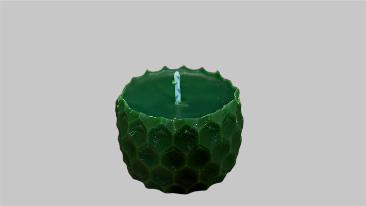
The end result is a paraffin candle that successfully validates the workflow from parametric design to additive manufacturing. The piece captures the essence of the digital model, demonstrating that printed molds are a viable and cost-effective alternative for producing short runs. Key learnings for future iterations: Joint Management: To eliminate the perimeter gap, the next step will be to integrate an overflow channel and a mechanical screw fastening system into the mold design. Surface Finish: The texture of print layers is visible in paraffin. For a "mirror" finish, the use of epoxy coatings on the mold or the use of resin printers (SLA) for the masterpieces will be explored. Scalability: The success of this prototype lays the groundwork for exploring more complex materials, such as two-component resins or fine concrete, using the same rigid mold logic.