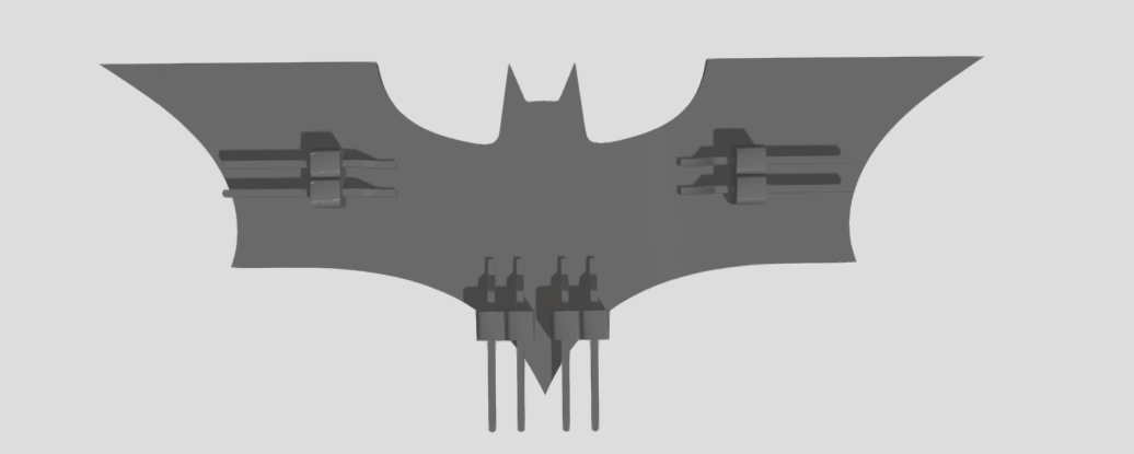
// BATMAN image code
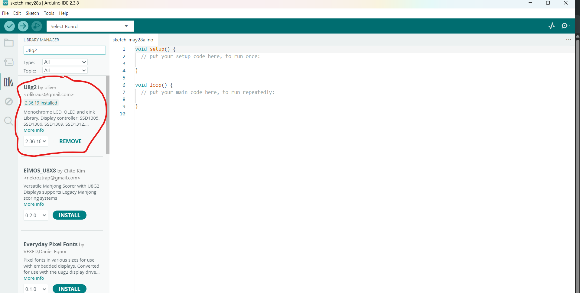
#include
#include
#include
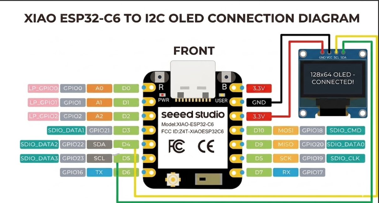
// Initialize the SH1106 OLED display using hardware I2C communication.
// U8G2_R0 configuration specifies no rotation (landscape orientation layout).
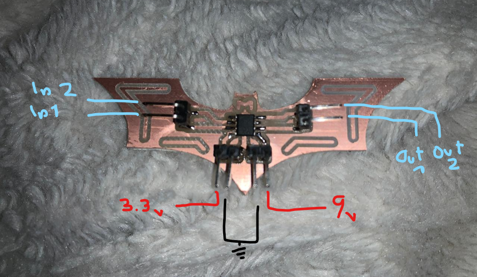
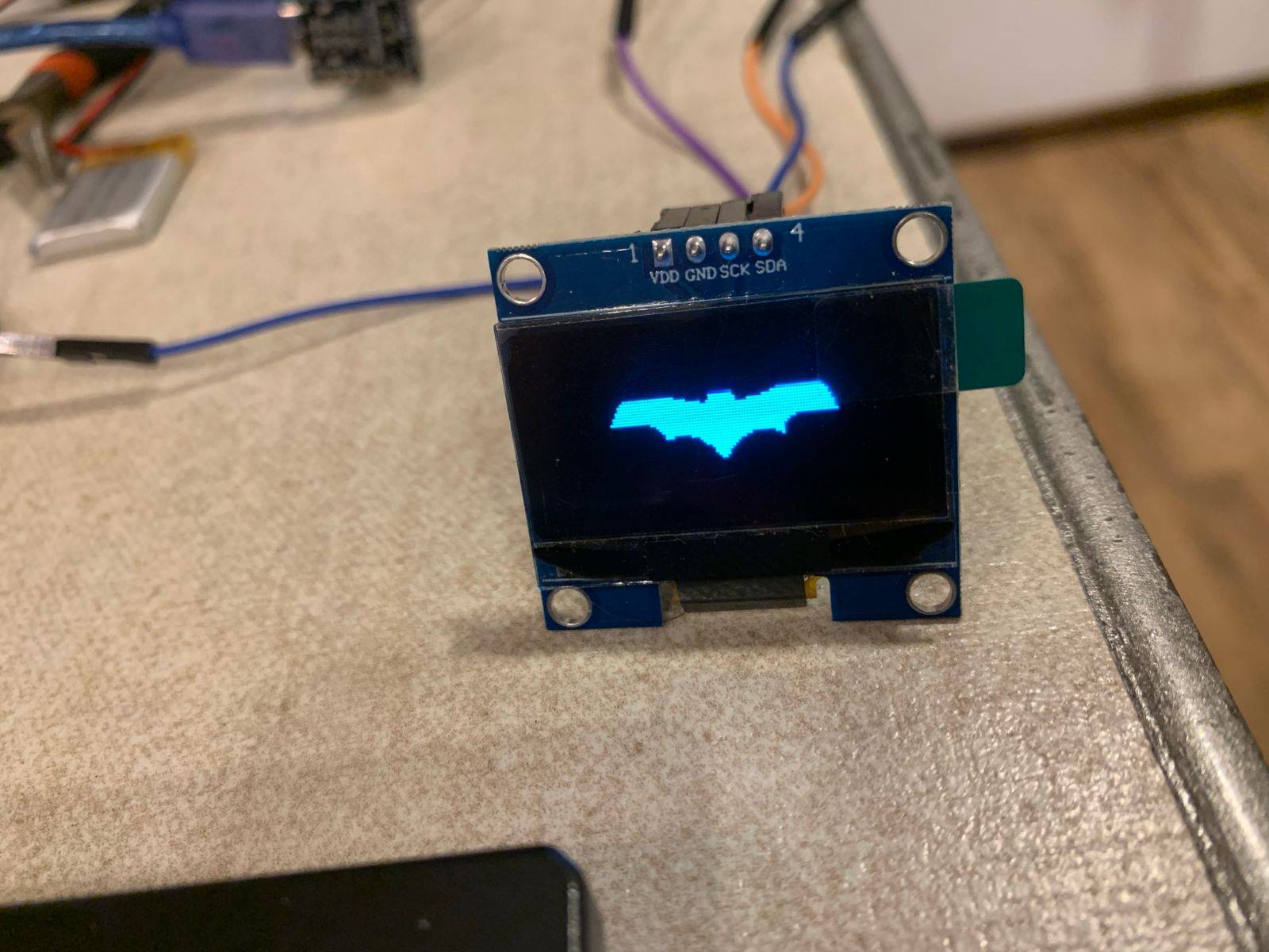
U8G2_SH1106_128X64_NONAME_F_HW_I2C u8g2(U8G2_R0, /* reset=*/ U8X8_PIN_NONE);
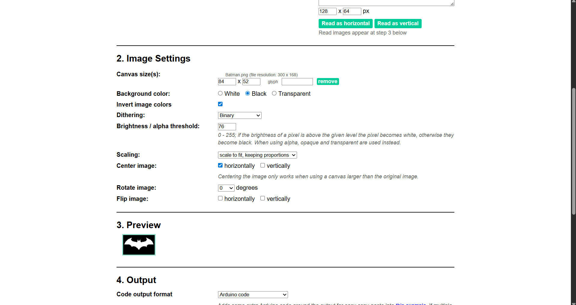
// --- BATMAN LOGO BITMAP ARRAY (84x52 px) ---
// Stored in flash memory using the PROGMEM keyword to save active dynamic RAM (SRAM).
const unsigned char epd_bitmap_Batman [] PROGMEM = {
0x00, 0x00, 0x00, 0x00, 0x00, 0x00, 0x00, 0x00, 0x00, 0x00, 0x00, 0x00, 0x00, 0x00, 0x00, 0x00,
0x00, 0x00, 0x00, 0x00, 0x00, 0x00, 0x00, 0x00, 0x00, 0x00, 0x00, 0x00, 0x00, 0x00, 0x00, 0x00,
0x00, 0x00, 0x00, 0x00, 0x00, 0x00, 0x00, 0x00, 0x00, 0x00, 0x00, 0x00, 0x00, 0x00, 0x00, 0x00,
0x00, 0x00, 0x00, 0x00, 0x00, 0x00, 0x00, 0x00, 0x00, 0x00, 0x00, 0x00, 0x00, 0x00, 0x00, 0x00,
0x00, 0x00, 0x00, 0x00, 0x00, 0x00, 0x00, 0x00, 0x00, 0x00, 0x00, 0x00, 0x00, 0x00, 0x00, 0x02,
0x00, 0x00, 0x00, 0x00, 0x06, 0x00, 0x00, 0x00, 0x00, 0x00, 0x1e, 0x00, 0x00, 0x00, 0x00, 0x03,
0x80, 0x00, 0x00, 0x00, 0x00, 0x7c, 0x00, 0x00, 0x00, 0x00, 0x03, 0xe0, 0x00, 0x00, 0x00, 0x01,
0xfc, 0x00, 0x00, 0x00, 0x00, 0x01, 0xf8, 0x00, 0x00, 0x00, 0x07, 0xf8, 0x00, 0x00, 0x00, 0x00,
0x01, 0xfe, 0x00, 0x00, 0x00, 0x0f, 0xf8, 0x00, 0x01, 0x04, 0x00, 0x01, 0xff, 0x80, 0x00, 0x00,
0x1f, 0xfc, 0x00, 0x01, 0x0c, 0x00, 0x03, 0xff, 0xc0, 0x00, 0x00, 0x3f, 0xfe, 0x00, 0x03, 0x0c,
0x00, 0x03, 0xff, 0xe0, 0x00, 0x00, 0x7f, 0xff, 0x00, 0x03, 0xfc, 0x00, 0x07, 0xff, 0xf0, 0x00,
0x00, 0xff, 0xff, 0xc0, 0x03, 0xfc, 0x00, 0x1f, 0xff, 0xf8, 0x00, 0x01, 0xff, 0xff, 0xfc, 0x03,
0xfe, 0x00, 0xff, 0xff, 0xfc, 0x00, 0x03, 0xff, 0xff, 0xff, 0xe7, 0xfe, 0x1f, 0xff, 0xff, 0xfc,
0x00, 0x03, 0xff, 0xff, 0xff, 0xff, 0xff, 0xff, 0xff, 0xff, 0xfe, 0x00, 0x07, 0xff, 0xff, 0xff,
0xff, 0xff, 0xff, 0xff, 0xff, 0xfe, 0x00, 0x07, 0xff, 0xff, 0xff, 0xff, 0xff, 0xff, 0xff, 0xff,
0xff, 0x00, 0x0f, 0xff, 0xff, 0xff, 0xff, 0xff, 0xff, 0xff, 0xff, 0xff, 0x00, 0x0f, 0xff, 0xff,
0xff, 0xff, 0xff, 0xff, 0xff, 0xff, 0xff, 0x00, 0x1f, 0xff, 0xff, 0xff, 0xff, 0xff, 0xff, 0xff,
0xff, 0xff, 0x80, 0x00, 0x00, 0x7f, 0xff, 0xff, 0xff, 0xff, 0xff, 0xe0, 0x00, 0x00, 0x00, 0x00,
0x1f, 0xff, 0xff, 0xff, 0xff, 0xff, 0x80, 0x00, 0x00, 0x00, 0x00, 0x0f, 0xff, 0xff, 0xff, 0xff,
0xff, 0x00, 0x00, 0x00, 0x00, 0x00, 0x07, 0xff, 0xff, 0xff, 0xff, 0xfe, 0x00, 0x00, 0x00, 0x00,
0x00, 0x03, 0xff, 0xff, 0xff, 0xff, 0xfe, 0x00, 0x00, 0x00, 0x00, 0x00, 0x03, 0x81, 0xff, 0xff,
0xf0, 0x0e, 0x00, 0x00, 0x00, 0x00, 0x00, 0x00, 0x00, 0x3f, 0xff, 0xc0, 0x02, 0x00, 0x00, 0x00,
0x00, 0x00, 0x00, 0x00, 0x1f, 0xff, 0x00, 0x00, 0x00, 0x00, 0x00, 0x00, 0x00, 0x00, 0x00, 0x0f,
0xfe, 0x00, 0x00, 0x00, 0x00, 0x00, 0x00, 0x00, 0x00, 0x00, 0x03, 0xfc, 0x00, 0x00, 0x00, 0x00,
0x00, 0x00, 0x00, 0x00, 0x00, 0x01, 0xf8, 0x00, 0x00, 0x00, 0x00, 0x00, 0x00, 0x00, 0x00, 0x00,
0x01, 0xf0, 0x00, 0x00, 0x00, 0x00, 0x00, 0x00, 0x00, 0x00, 0x00, 0x00, 0xf0, 0x00, 0x00, 0x00,
0x00, 0x00, 0x00, 0x00, 0x00, 0x00, 0x00, 0x60, 0x00, 0x00, 0x00, 0x00, 0x00, 0x00, 0x00, 0x00,
0x00, 0x00, 0x00, 0x00, 0x00, 0x00, 0x00, 0x00, 0x00, 0x00, 0x00, 0x00, 0x00, 0x00, 0x00, 0x00,
0x00, 0x00, 0x00, 0x00, 0x00, 0x00, 0x00, 0x00, 0x00, 0x00, 0x00, 0x00, 0x00, 0x00, 0x00, 0x00,
0x00, 0x00, 0x00, 0x00, 0x00, 0x00, 0x00, 0x00, 0x00, 0x00, 0x00, 0x00, 0x00, 0x00, 0x00, 0x00,
0x00, 0x00, 0x00, 0x00, 0x00, 0x00, 0x00, 0x00, 0x00, 0x00, 0x00, 0x00, 0x00, 0x00, 0x00, 0x00,
0x00, 0x00, 0x00, 0x00, 0x00, 0x00, 0x00, 0x00, 0x00, 0x00, 0x00, 0x00, 0x00, 0x00, 0x00, 0x00,
0x00, 0x00, 0x00, 0x00, 0x00, 0x00, 0x00, 0x00, 0x00, 0x00, 0x00, 0x00, 0x00, 0x00, 0x00, 0x00,
0x00, 0x00, 0x00, 0x00, 0x00, 0x00, 0x00, 0x00, 0x00, 0x00, 0x00, 0x00, 0x00, 0x00, 0x00, 0x00,
0x00, 0x00, 0x00, 0x00, 0x00, 0x00, 0x00, 0x00, 0x00, 0x00, 0x00, 0x00, 0x00, 0x00, 0x00, 0x00, 0x00, 0x00, 0x00, 0x00, 0x00, 0x00, 0x00, 0x00, 0x00, 0x00, 0x00, 0x00
};
void setup() {
// Initialize the screen structure, configure I2C communication pins,
// and clear the display panel controller to receive bytes.
u8g2.begin();
}
void loop() {
// Clear the internal buffer matrix before drawing new data frameworks.
u8g2.clearBuffer();
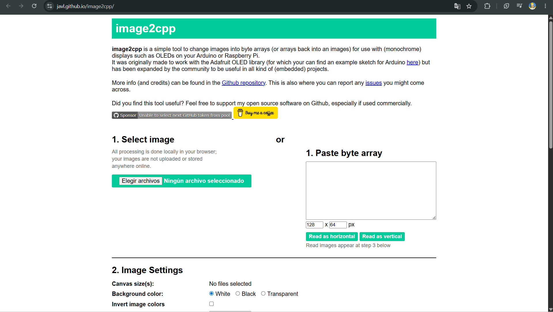
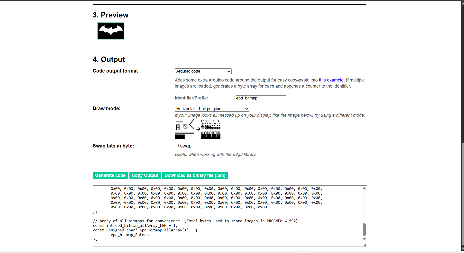
// === CRITICAL RENDERING PROCESS ===
// 1. Use the standard 'drawBitmap' method instead of 'drawXBMP'
// to properly map the standard output format generated by image2cpp.
// 2. Compute rows byte allocation: divide total pixel width by 8 bits
// and round values upwards: (84 width pixels + 7 padding bits) / 8 = 11 bytes per row.
// 3. Layout Positioning Coordinates: X=22, Y=6. This centers the 84x52 matrix
// perfectly inside the active screen window boundary resolution (128x64).
u8g2.drawBitmap(22, 6, 11, 52, epd_bitmap_Batman);
// Push data frames out from the microcontroller buffer directly to the display physical controller.
u8g2.sendBuffer();
// Maintain rendering execution stable on screen for 5000 milliseconds before repeating loop.
delay(5000);
}