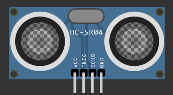
Ultrasonic Connection
> ECHO: GPIO 27 (D1)
> VCC/GND: 3.3V & GND
STATUS: [ACTIVE]
STATUS: [READ_ONLY]
STAGE 02: [ DIY VELOSTAT BUTTON ]
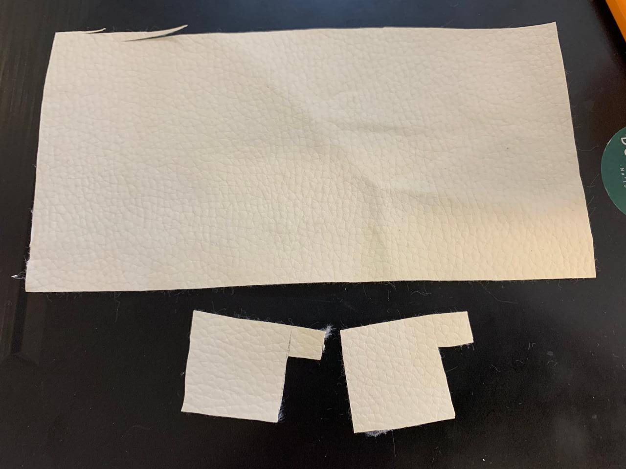
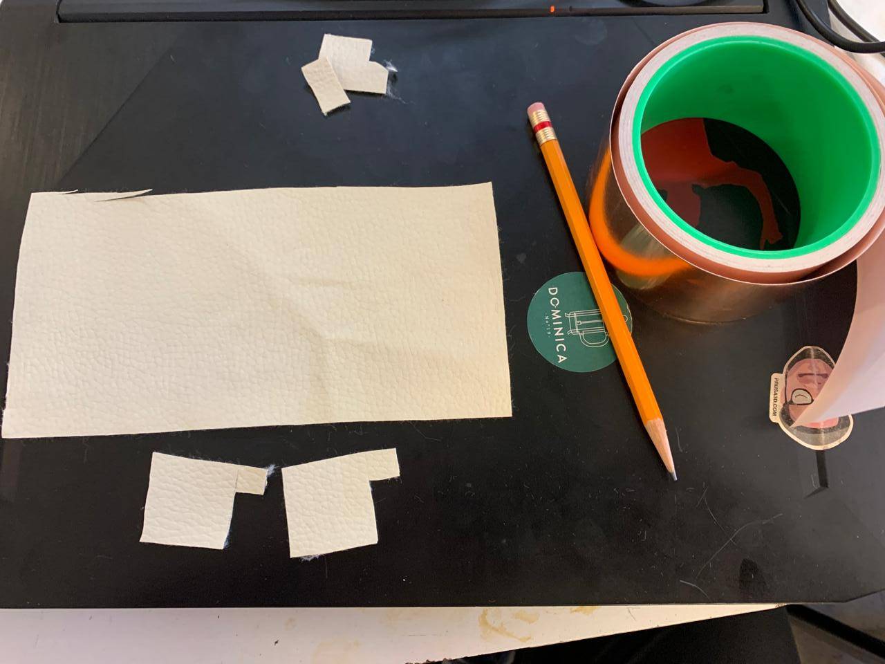
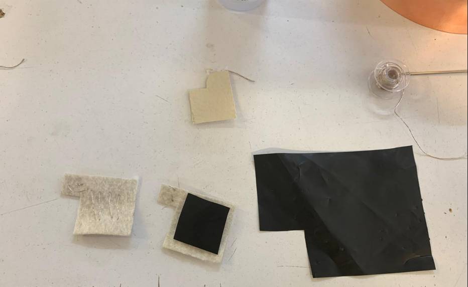
Materials
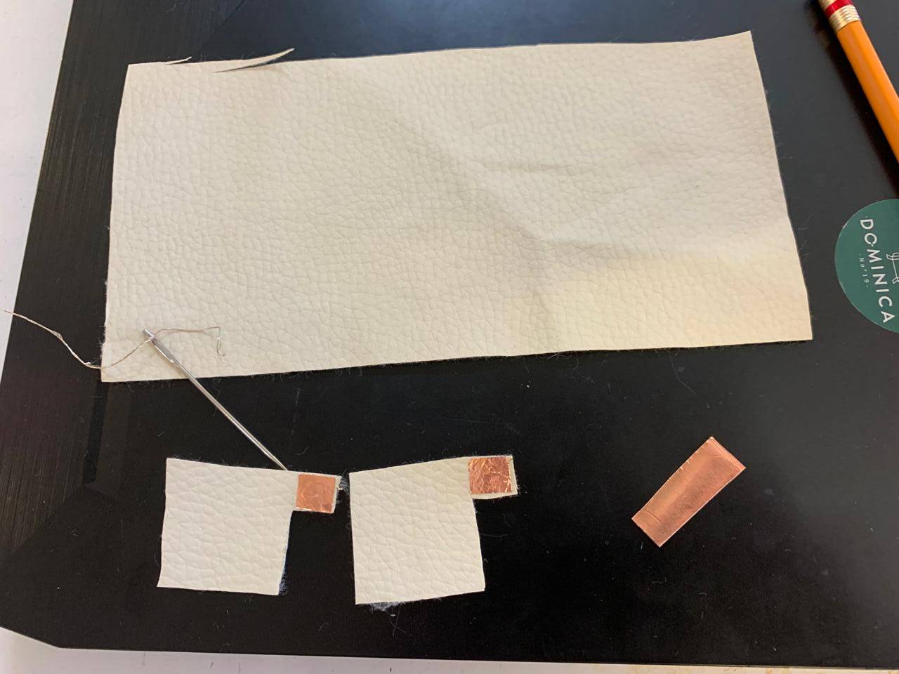
An insulating material is needed for the exterior.For the exterior, an insulating material is needed. When cutting the material, it is necessary to leave tabs on both sides, as seen in the image.
Conductivity
To conduct electricity in the button, it is necessary to use a copper sheet.
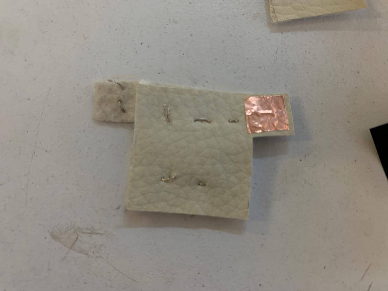
Calibration
The copper sheet needs to be glued to the button tabs.
Calibration
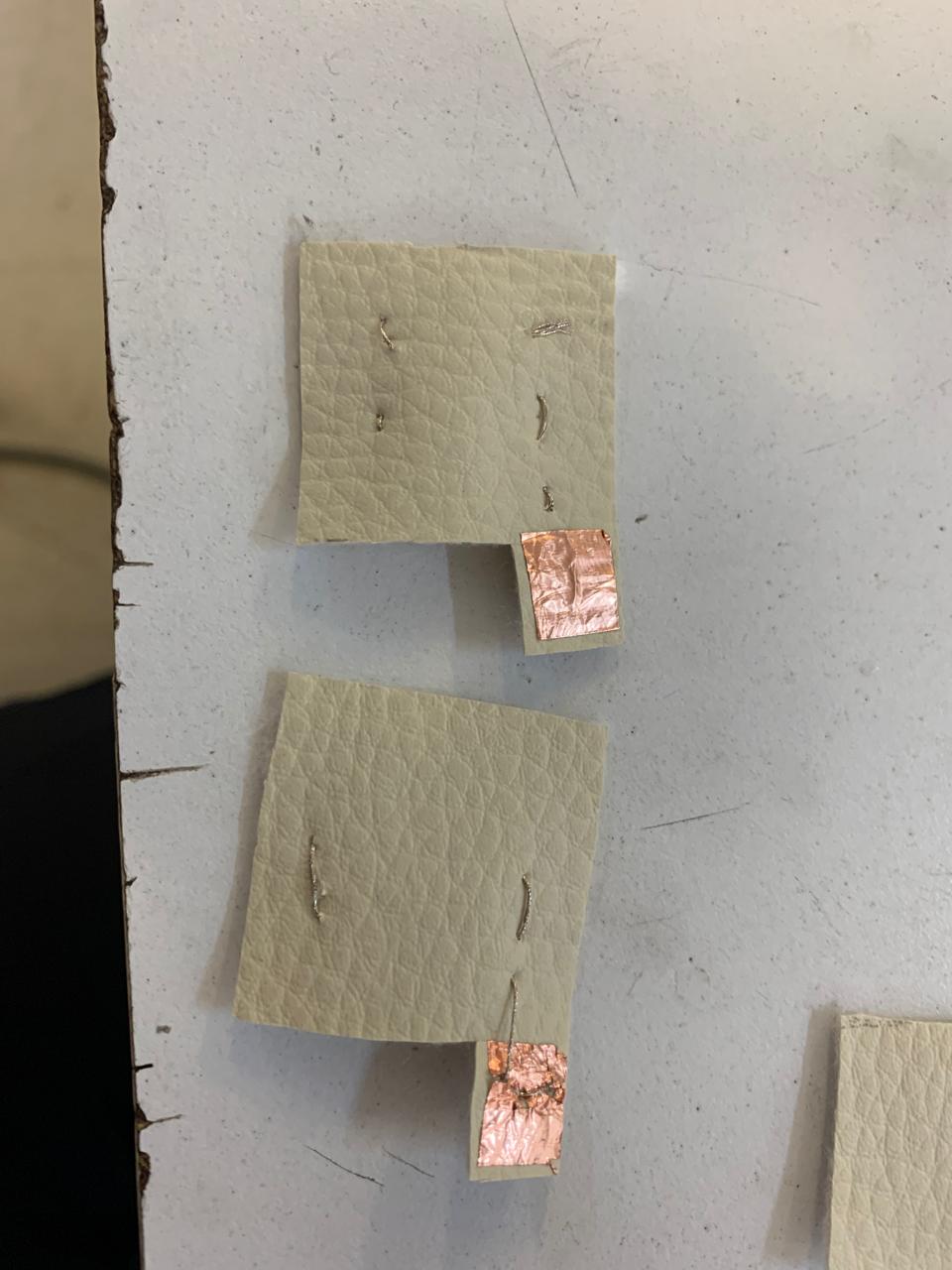
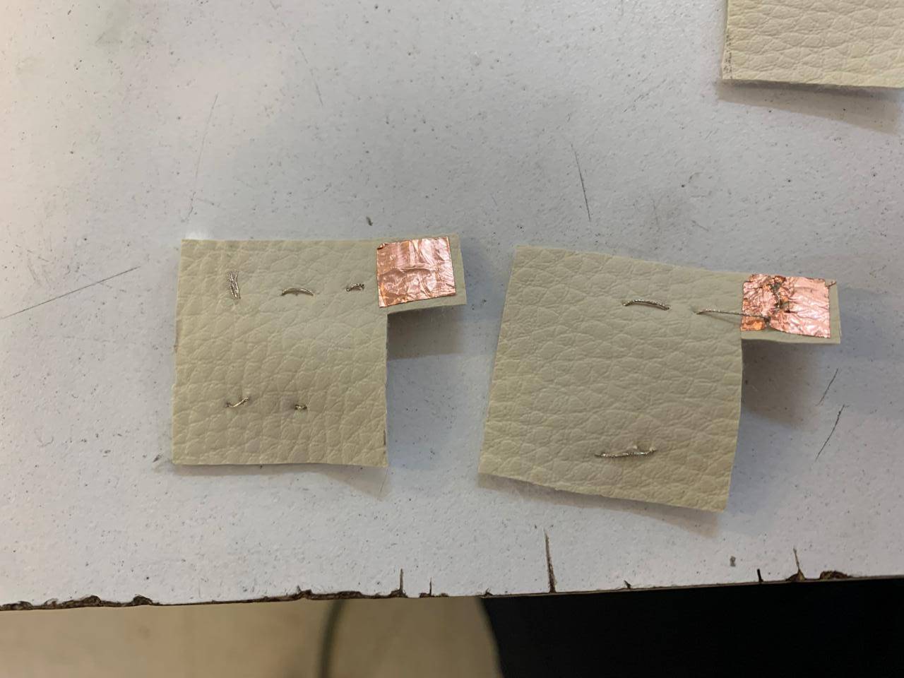
Using conductive thread, it is necessary to sew a pattern starting with the copper strip, so that they touch each other at all times.
Sewing pattern
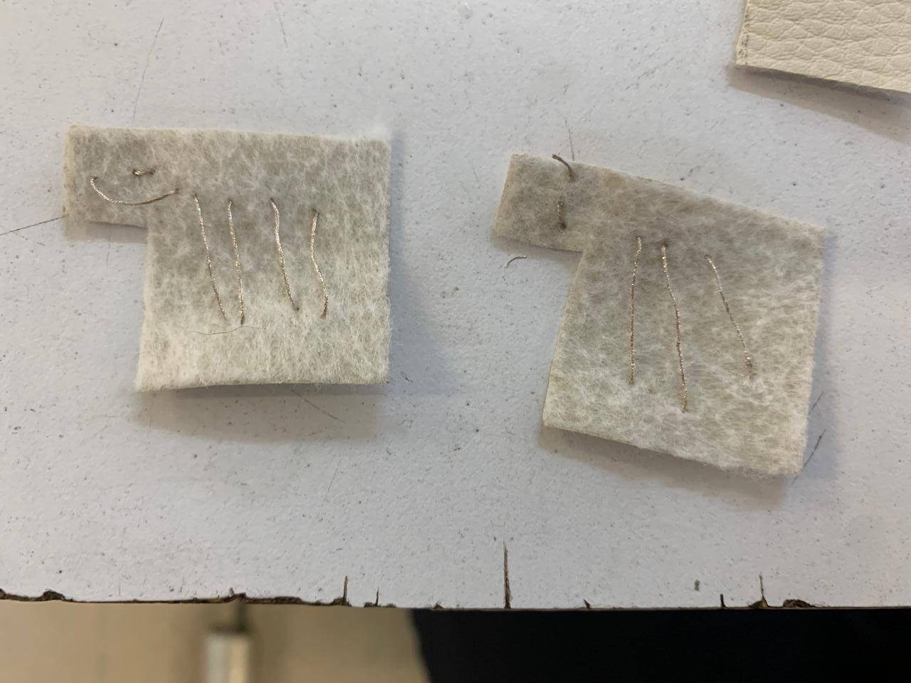
To sew the pattern correctly, it is necessary to sew diagonal lines like those shown in the image, so that when both sides are pressed together, the conductive thread touches.
Velostat
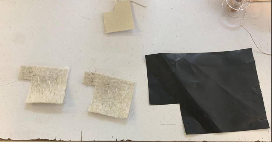
The most important part of the button is the velostat, which is a material that changes its resistance value when deformed, which means that by reading the resistance values of this material in an analogous way, it is possible to know when it is being pressed.
Velostat placement
The velostat should be placed in the middle of the two button pieces that are made, so that it is between the two sides that are conducting electricity, which will allow us to read its resistance value.
Closing the button
Finally, position the two outer pieces of the button so that the tabs are on opposite sides, as shown in the image, and secure them with either thread or glue. The copper pieces are there so that one side can be connected to GND and the other to an analog read pin.
VAL: [READING...]
STATUS: [READY_TO_COPY]
> TECHNICAL_CONSIDERATIONS
[ VARIABLES TO MODIFY IN THE CODE ]
Firmware tuning parameters to optimize the sensor's response:
- Thresholds: Defines the analog trigger point (0-1023) to filter noise.
- Smoothing: Moving average sample size to stabilize physical jitter.
- Mapping: Scaling raw input to match your specific output device range.
[ ADJUSTING SENSOR SENSITIVITY ]
Methods to fine-tune the physical and digital interaction:
- Mechanical: Adjust contact surface area or add foam spacers.
- Electrical: Swap the voltage divider reference resistor to shift input sensitivity.
- Software: Apply exponential scaling to prioritize light or heavy pressure.
PRINTING FILES
Download the toy that I made.