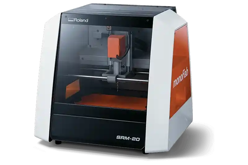
MonoFab SRM-20
> VOLUME: 203.2 x 152.4 x 60.5 mm
> SPINDLE: 7,000 RPM
Design Inspiration & Kicad Exporting
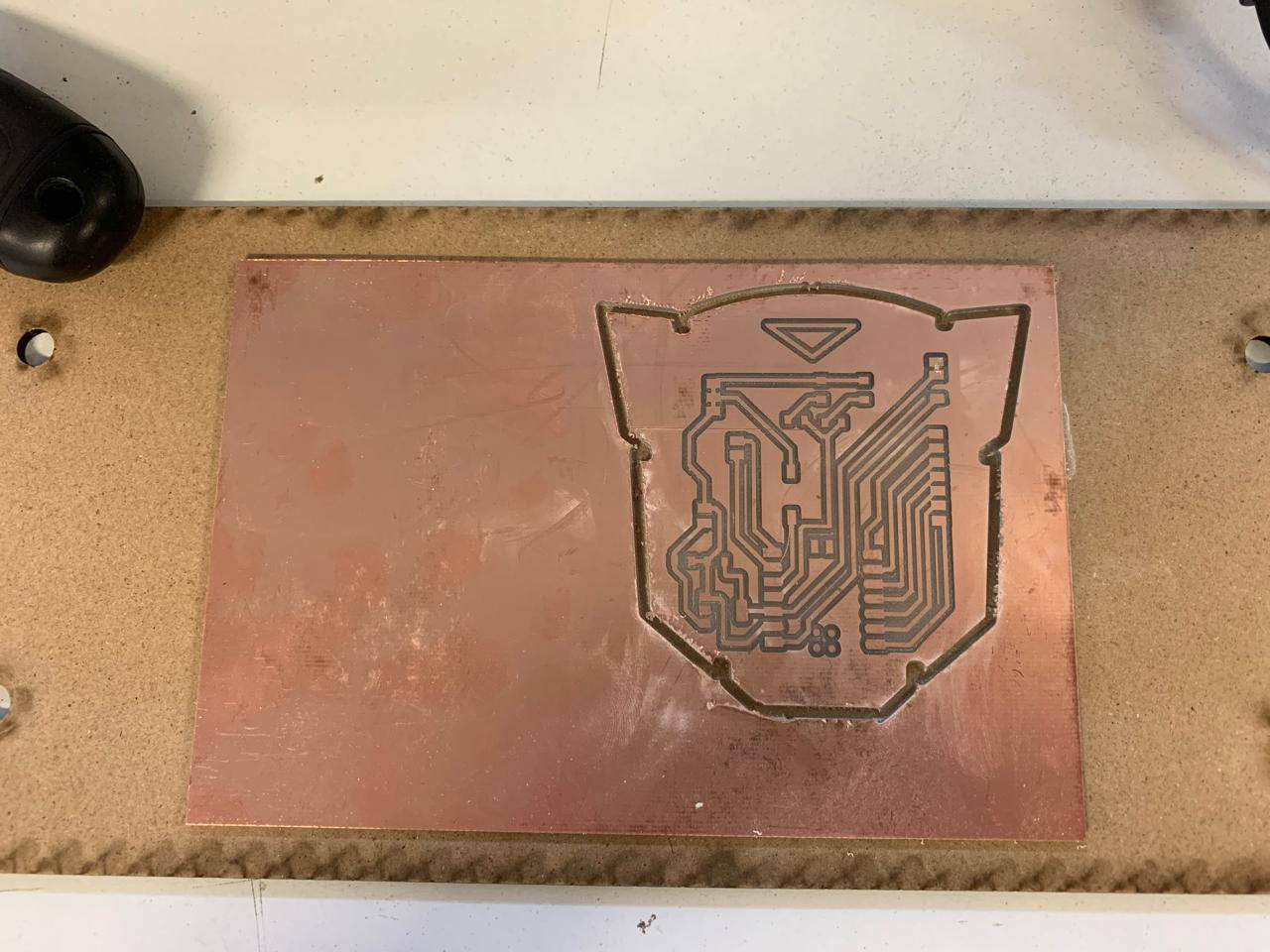
For this week, the challenge was to move from a breadboard prototype to a professional permanent circuit. For that I used a Monofab, and a Copper with fiberglass botom plaque. Taking inspiration form my friend's Oscar Hernandez plaque I decided to make a module for Autobot design from Transformers, since he made one out of the decepticons logo.
1.- Exporting from KiCAD
> FIG 01: SVG_EXPORT_PROCESS.MP4

PROTOTYPE_V1
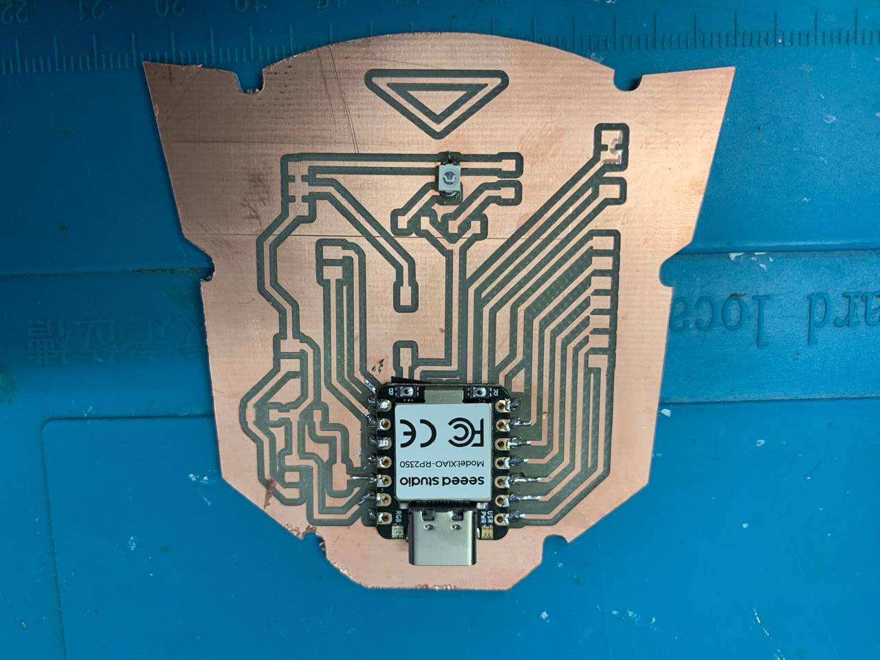
PRODUCTION_V2
STAGE 02: [ FILE CONVERSION ]
> TRACES_CALCULATION.MP4
> OUTLINE_CALCULATION.MP4
To prepare the file for the Monofab I used two SVG files, one for the inside milling and one for the outside milling, and for this I used a webpage called modsproject.
SOFTWARE SETUP: [ V-PANEL & DRIVERS ]
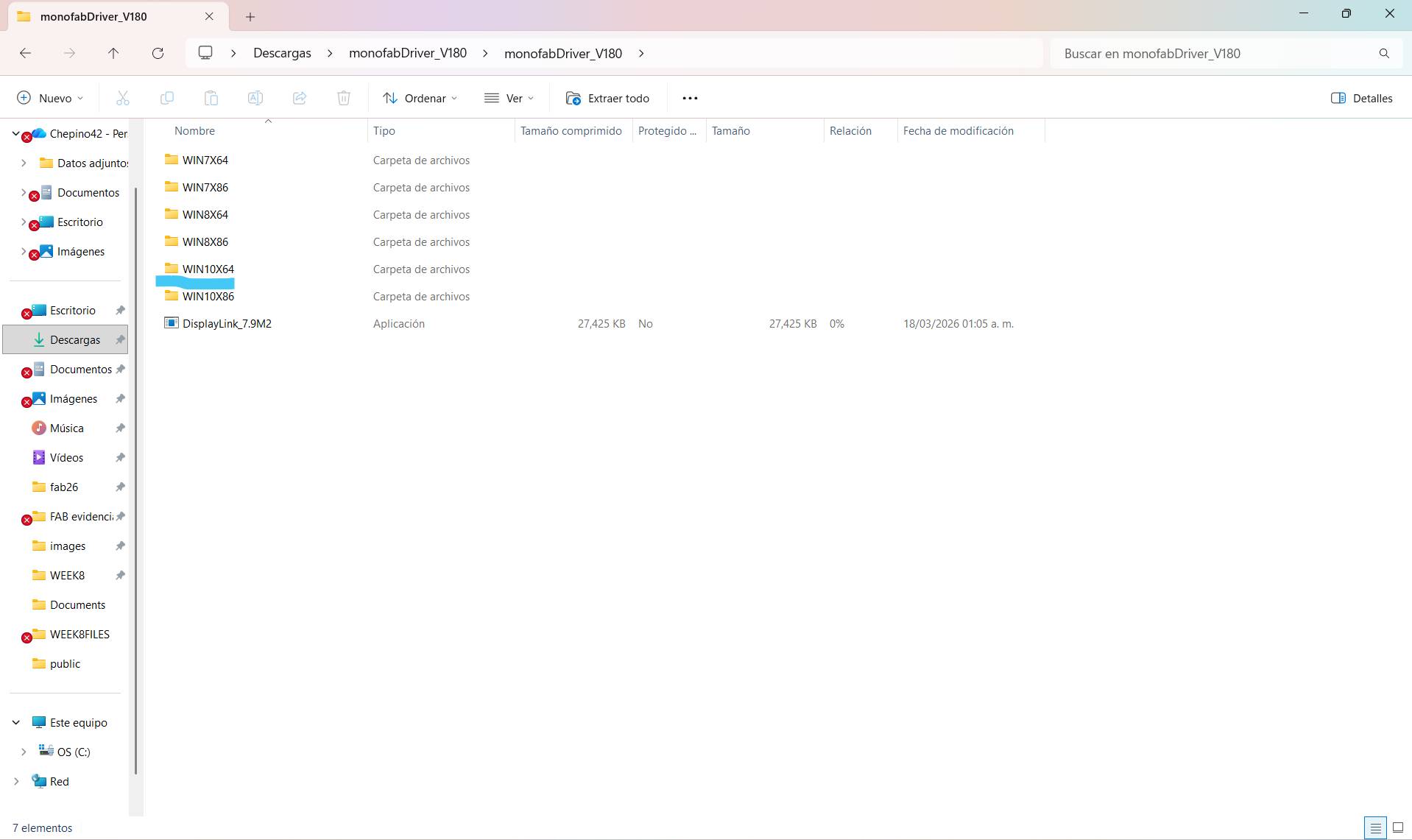
Download Drivers
You can download the drive folder using the attached link, depending on your Windows system.
DOWNLOAD_DRIVERS.EXE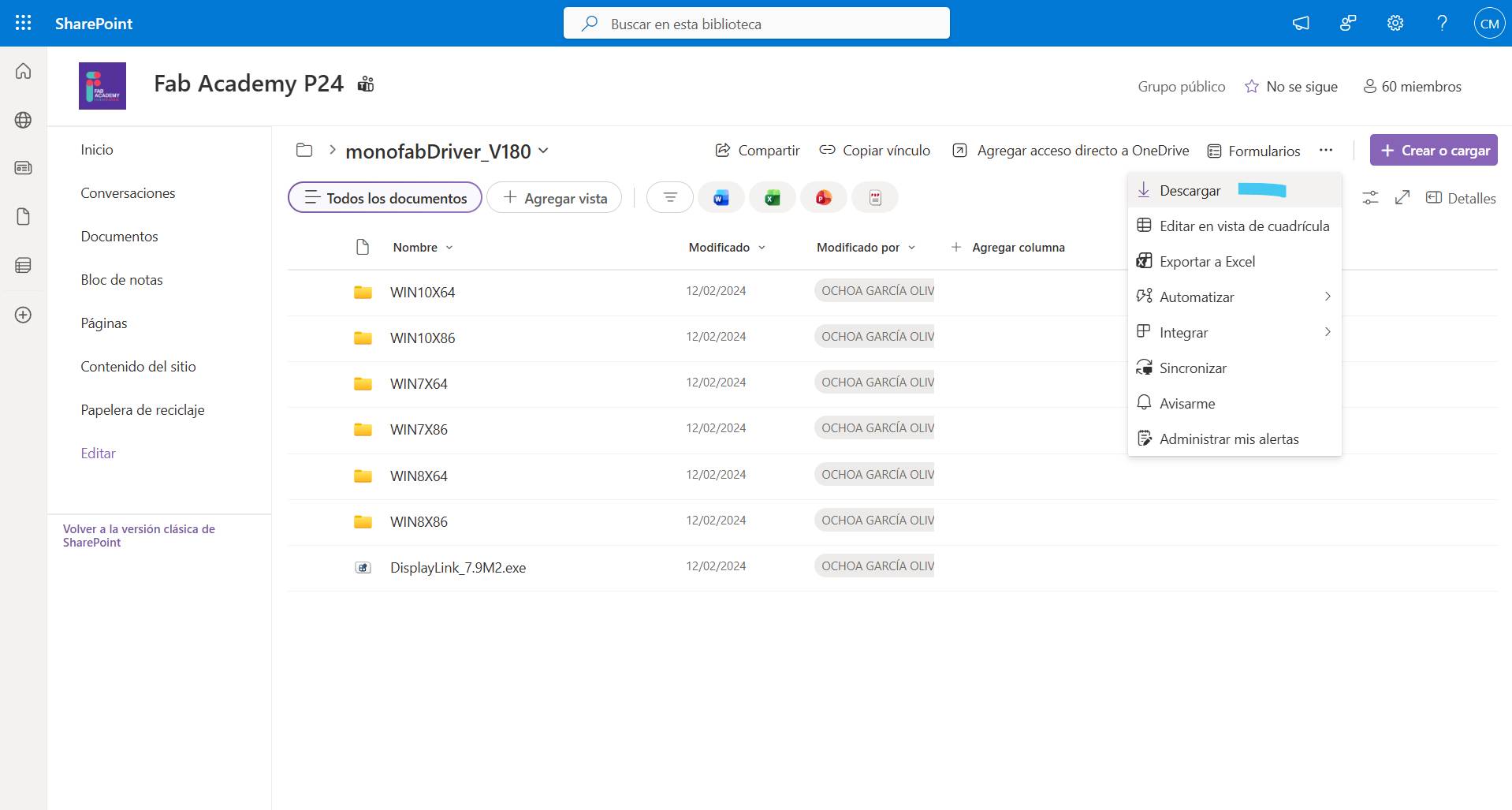
Driver Installation
In my case I used 8X64, but it depends on your computer and its specifications..
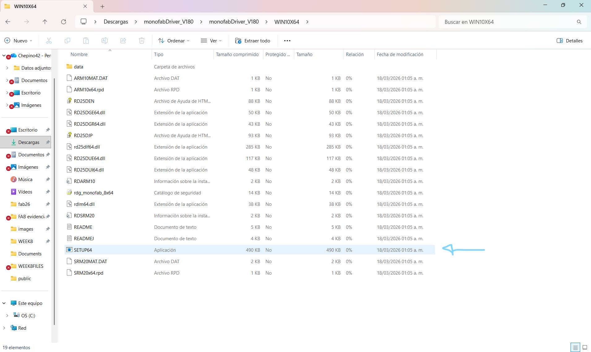
SETUP
Open the folder and look for SETUP64 or the corresponding SETUP as in the image and run it.
Get VPanel Software
For the next step, you need to download the VPANEL software using the link I've attached, and when you open the folder, run the file that says SETUP..
DOWNLOAD_VPANEL.ZIP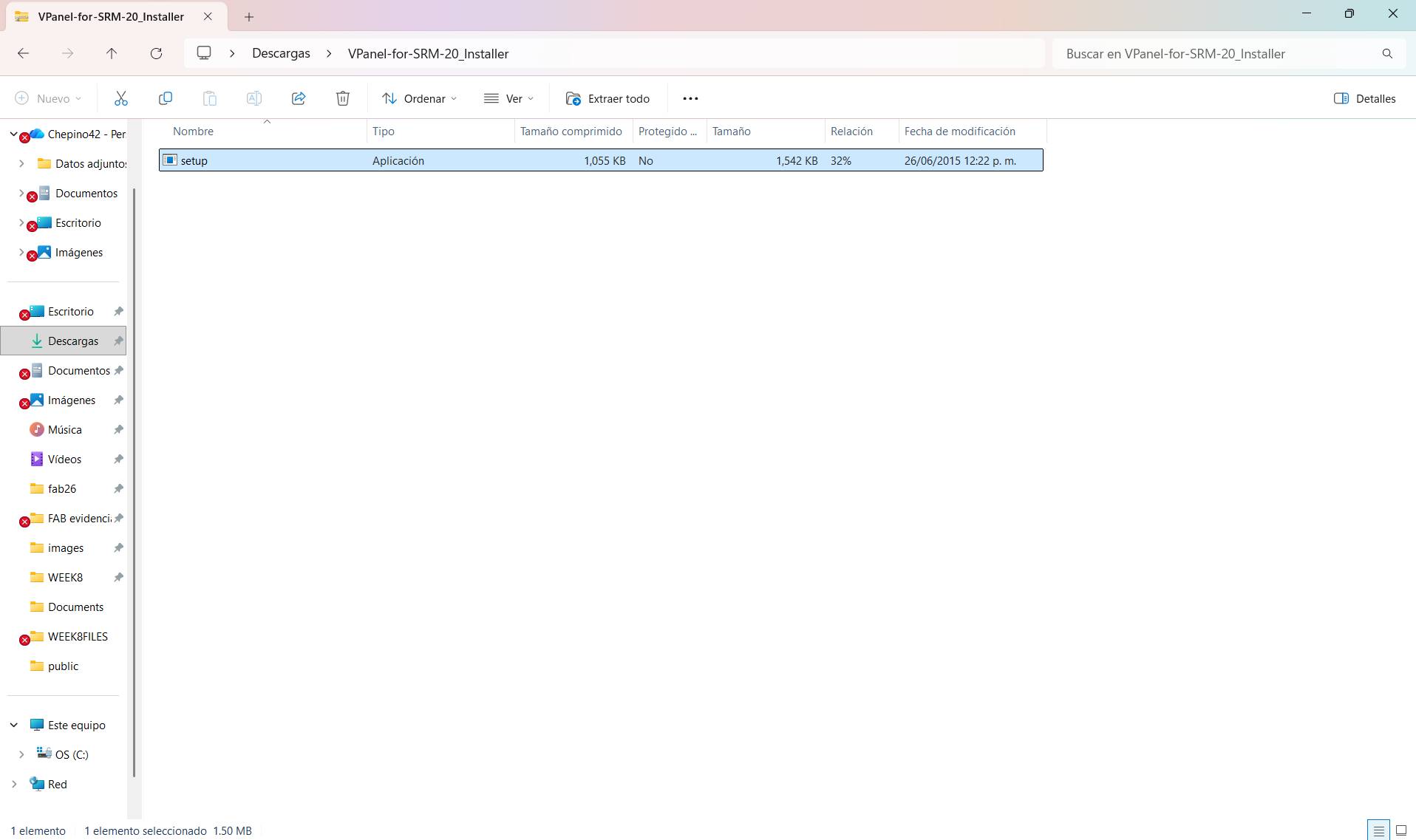
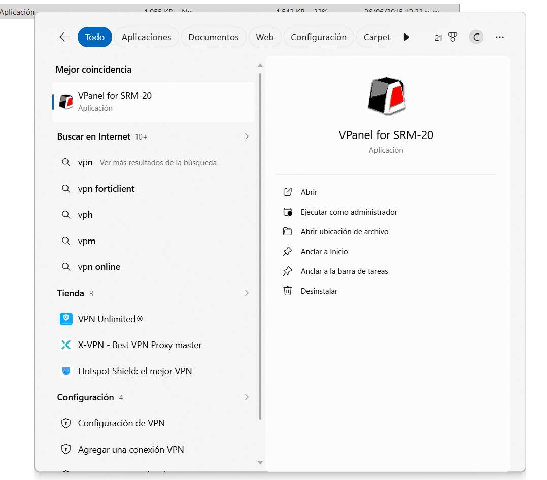
VPanel Software
A tab will appear, and you must accept all the prompts to install the program. If it was installed correctly, it should appear on your computer as follows. Remember that the program can only be run when your computer is connected to the Monofab..
STAGE 03: [ PCB MILLING ]
Machine Setup
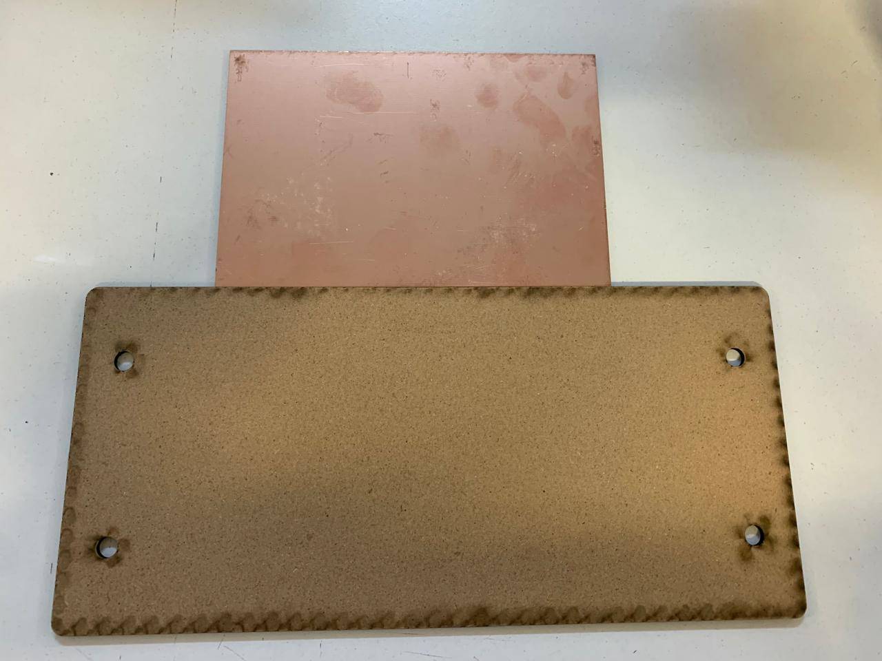
In order to mill your plaque you're gonna need your copper plaque and a wooden plaque to put underneath as a sacrifice.
Placing tape
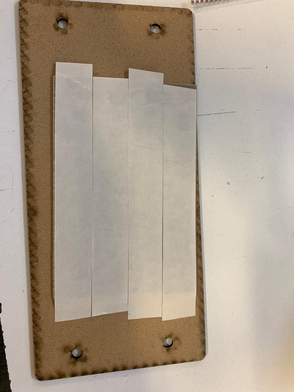
For your plaque no to move it's necessary for you to place double sided tape underneath de copper plaque.
Fixating the sacrifice
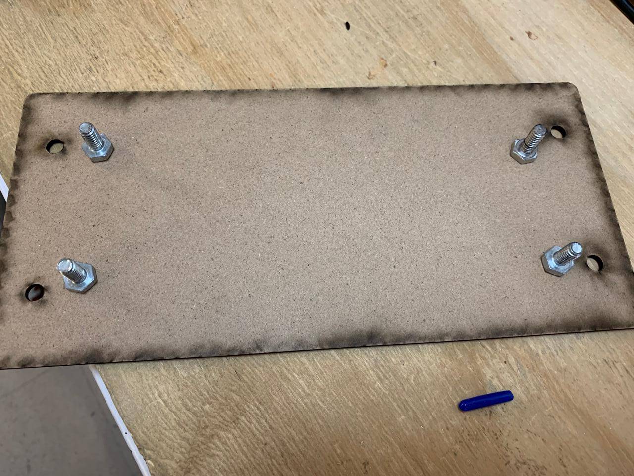
To fix the plaque on the machine it's necessary to use 4 screws.
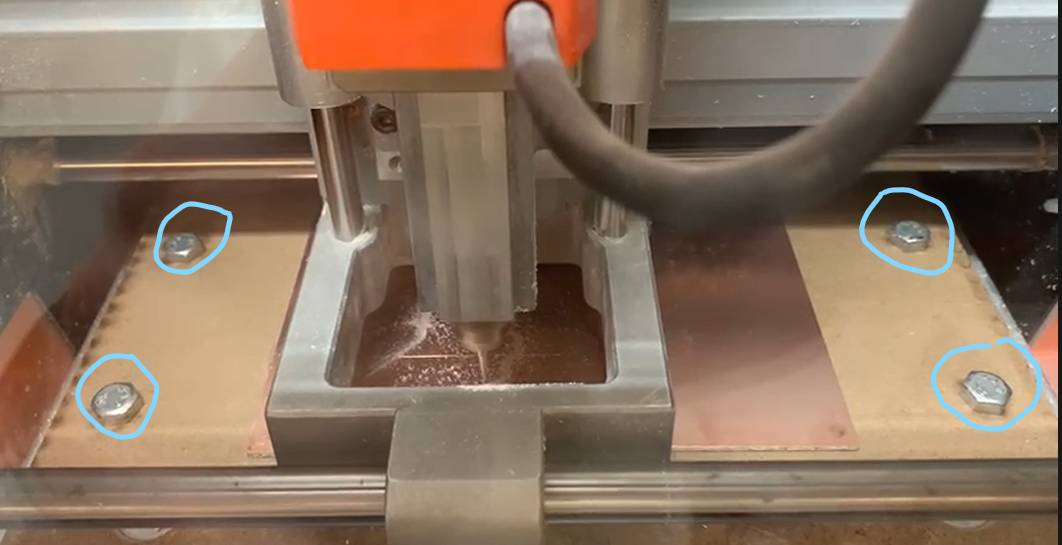
Screwing the plaque on to the Monofab
When you place your plaque on the machine it should look like this.
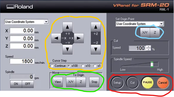
Vpanel Interface
Once you connect the machine to your computer and open the Vpanel software, you will be able to control the positioning of the tip on the x, y and z axes, as well as the origin and reference points..
VPanel Interface Guide
The yellow section contains the manual movement controls. "Continuous" allows movement until you release the button, while values like 100 or 10 define the exact distance moved per click.
In the blue section are the buttons you can use to set the origin points, both X/Y and Z.
Allows you to view the route to be executed, pause it, or return the machine to its marked origin point.
The "setup" button allows you to select your route, and "output" starts the cut. "Pause" resumes the job, while "Cancel" stops it completely.
> DEBUGGING_MODE: BOARD_TESTS
Verifying circuit integrity and logic.
TEST_01: CONTINUITY
TEST_02: SIGNAL_LOGIC
// Pin definition using 'D' nomenclature
const int buttonPin = D9;    // Button on D9
const int externalLedPin = D10; // Your LED on D10

// Variables to manage state
bool ledOn = false;
bool lastButtonState = HIGH;

void setup() {
  Serial.begin(9600);
  pinMode(buttonPin, INPUT_PULLUP);
  pinMode(externalLedPin, OUTPUT);
  digitalWrite(externalLedPin, LOW);
}

void loop() {
  bool currentButtonState = digitalRead(buttonPin);
  if (lastButtonState == HIGH && currentButtonState == LOW) {
    delay(50);
    ledOn = !ledOn;
    digitalWrite(externalLedPin, ledOn ? HIGH : LOW);
    while (digitalRead(buttonPin) == LOW) {
      delay(10);
    }
  }
  lastButtonState = currentButtonState;
}
PRODUCTION FILES UNLOCKED
Download SVG, RML and CAD source files.