My idea
For this project, I decided to make a chest of drawers to store my books and other things, since I have too many things scattered on my desk and I want more space to work. My final piece didn't turn out perfect; the drawer is fine, but the frame where I'm going to put the hinges came out too tight. When I finish correcting the mistake, I'll upload the final result.
CHOOSE PHASE:
[ V-CARVE PRO ]
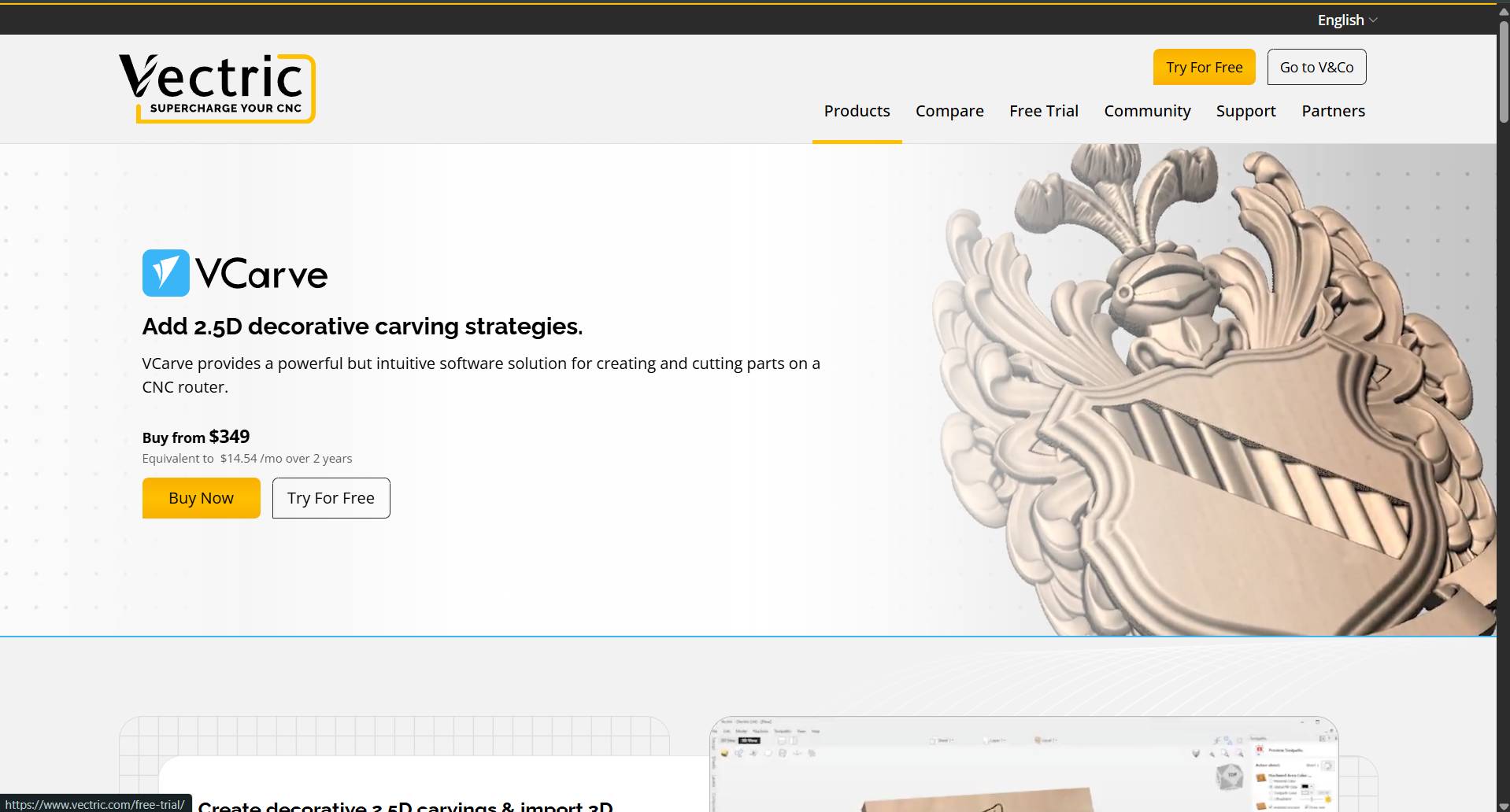
Installation
Download VCARVE Pro 12 to begin the toolpath configuration.
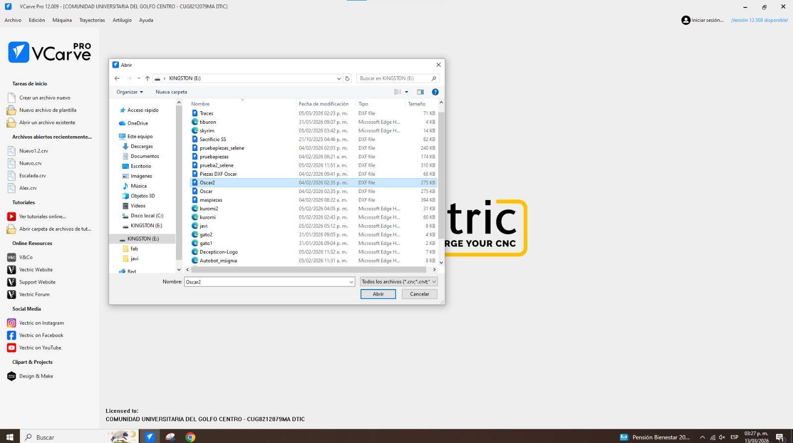
Open DXF
Once your file is ready in DXF format, open it from the main menu.
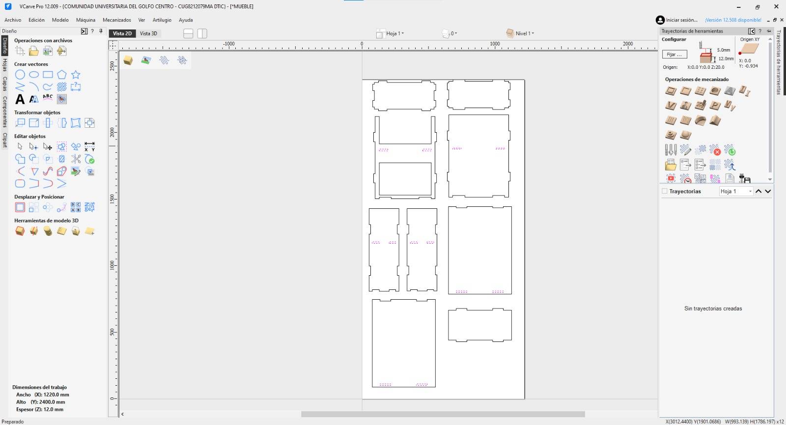
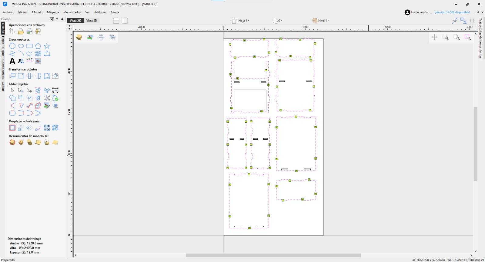
Visual Inspection
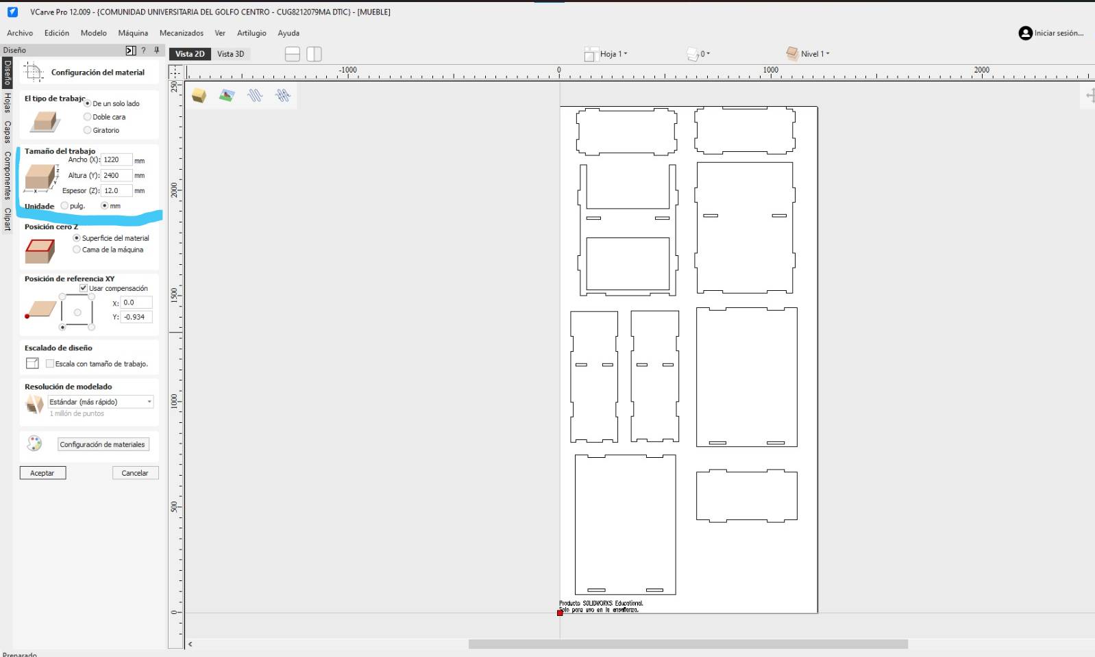
Your file should look like this. Check the dimensions on the left panel.
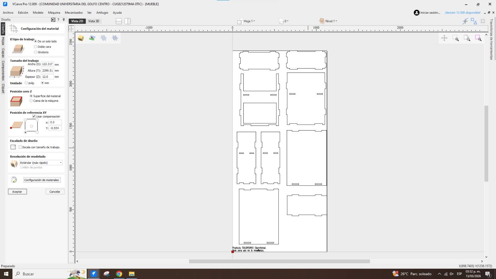
Job Size
Set the dimensions to 2400mm height and 1220mm width (Standard Plywood size).
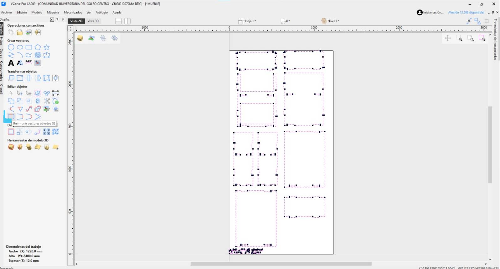
Join Vectors
Use the "Join Vectors" option to select shapes individually without selecting loose lines.
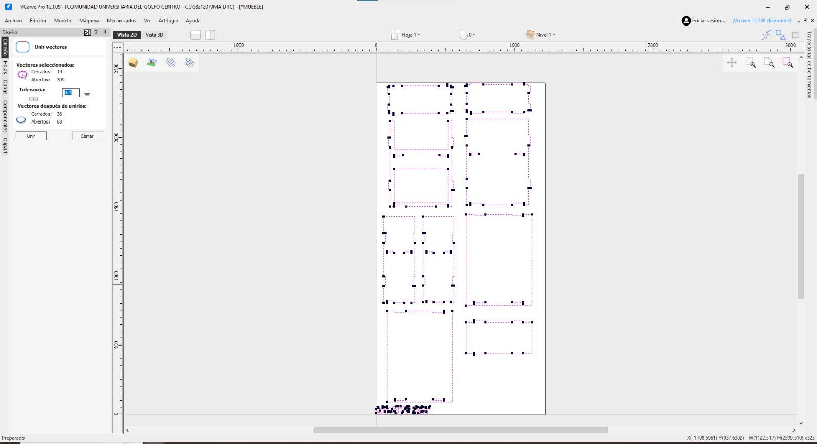
Vector OK
Press OK on the pop-up menu to confirm vector joining.
Internal Holes
Ensure internal holes are cut from the inside. Select all hole vectors first.
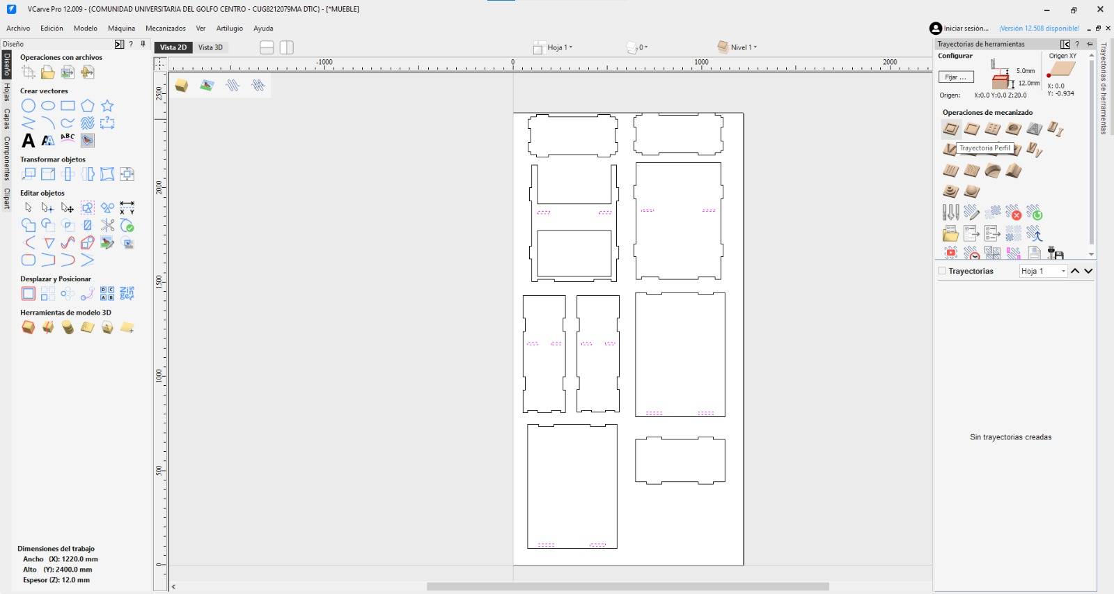
Toolpath Menu
To apply the cutting function, go to the Toolpath menu on the right panel.
Profile Toolpath
Select the "Profile Toolpath" icon to define the cutting strategy.
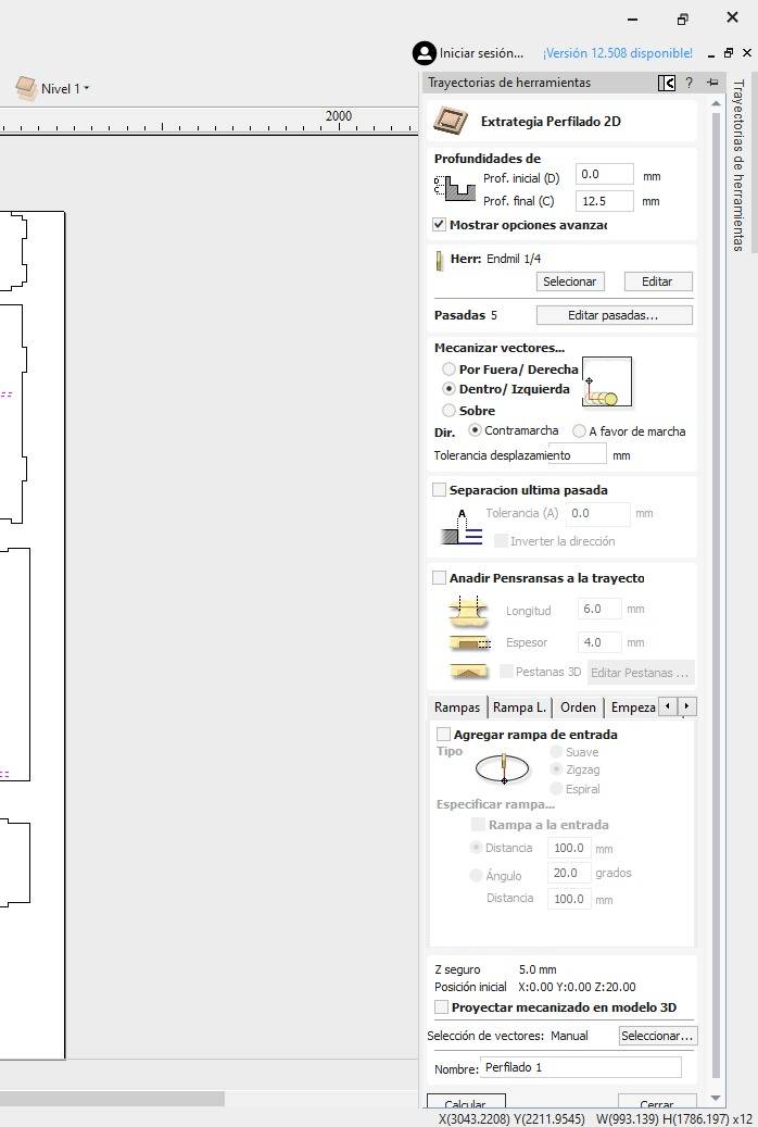
Inside Strategy
Select the Inside/Left option in the Machine Vectors section, then click Calculate. When cutting holes, we use the Inside/Left strategy to ensure the CNC bit stays on the inner side of our vector. This maintains the exact diameter of the hole, as the software compensates for the tool's radius. If we cut "On" the line, the hole would be larger than designed by exactly half the bit's diameter.
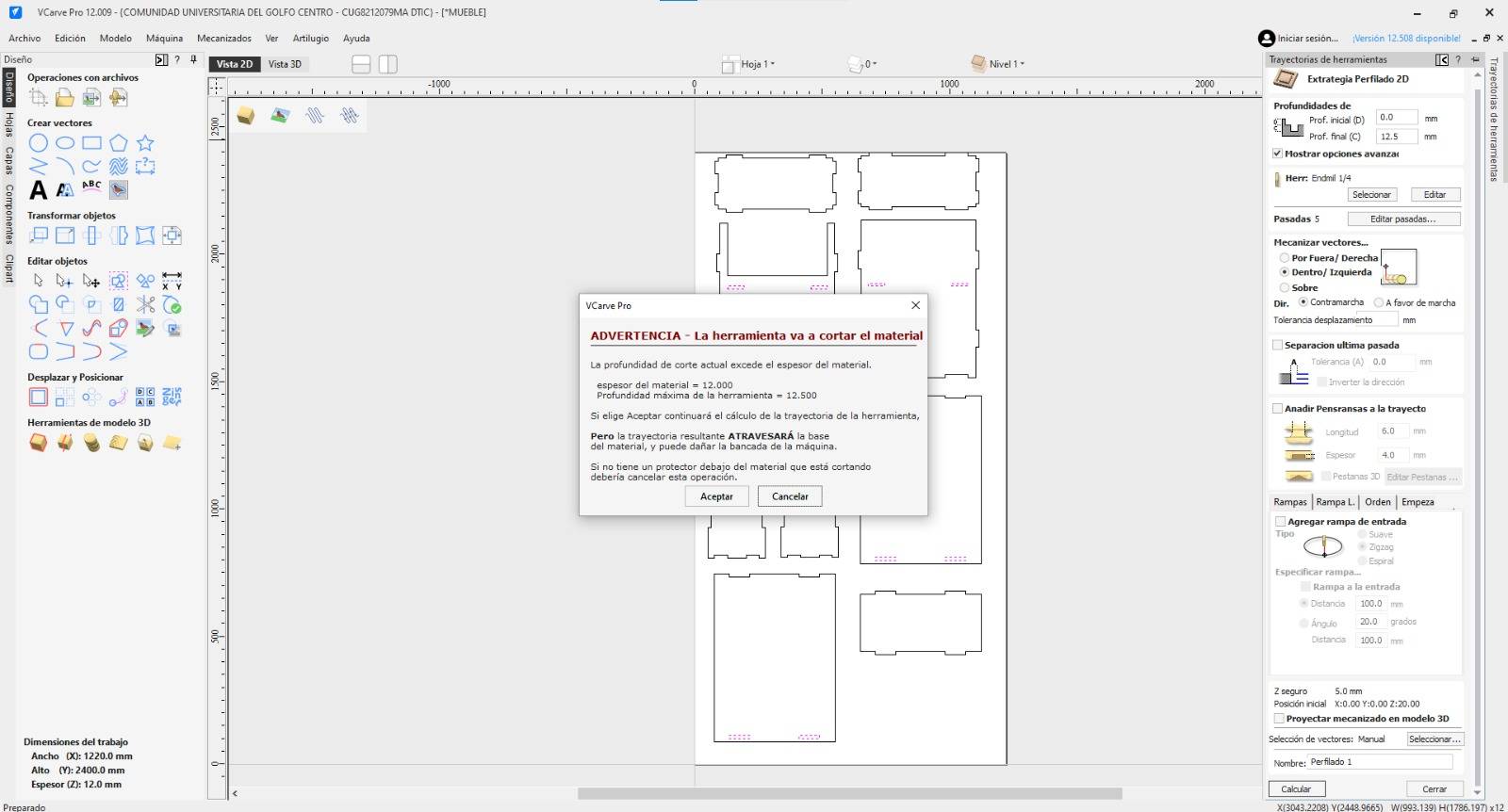
Warning OK
A warning will appear regarding cutting through the material. This is expected, click OK.
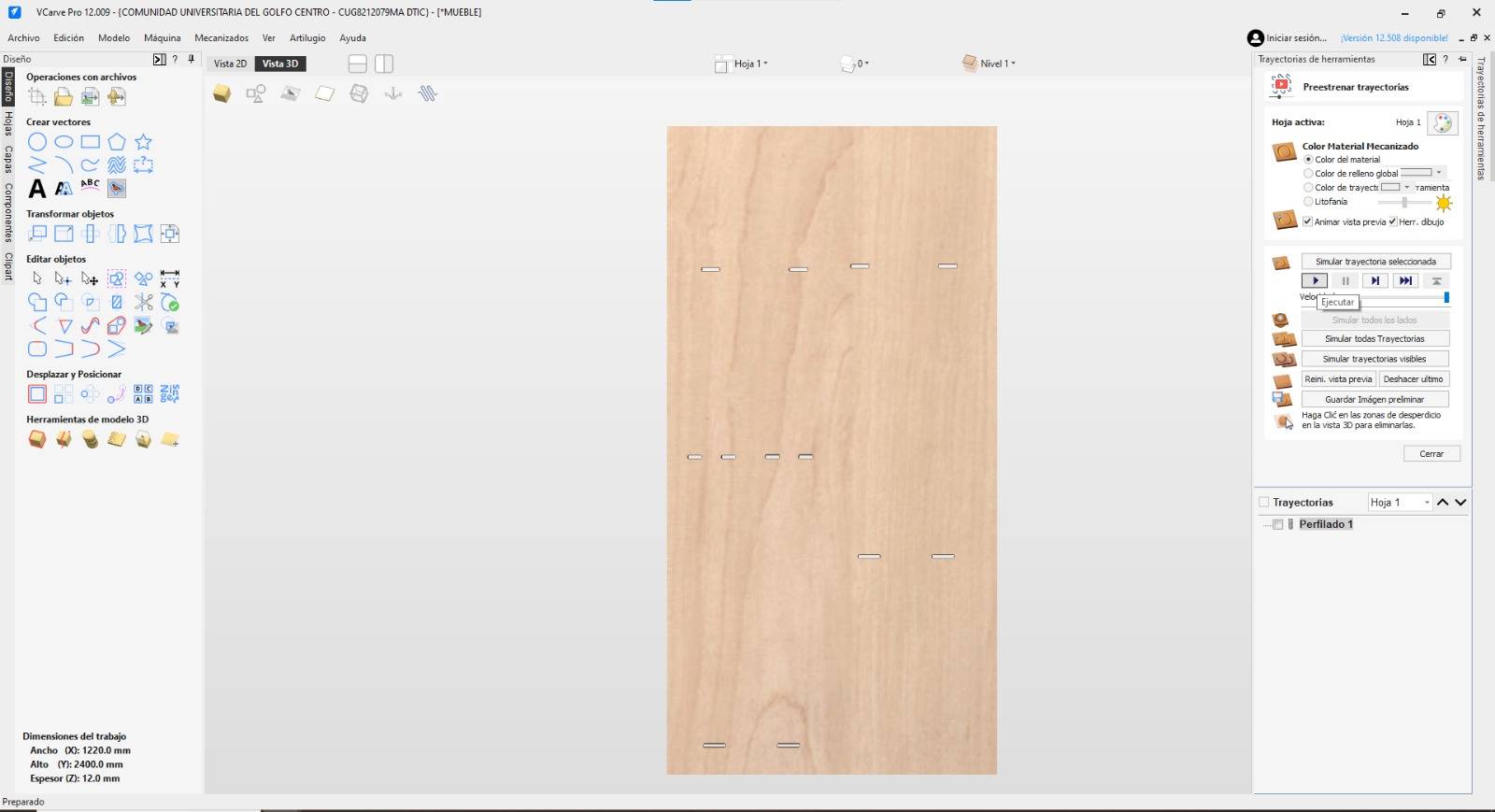
Visualizing Path
The software will show the path and cuts intended for the material.

Hole Simulation
Press Play to see the path the machine will follow for each hole.
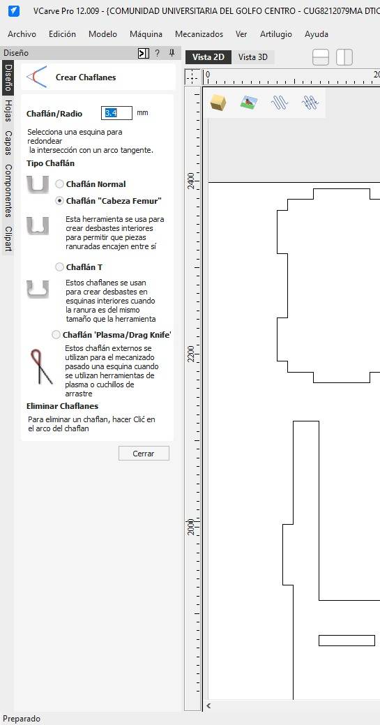
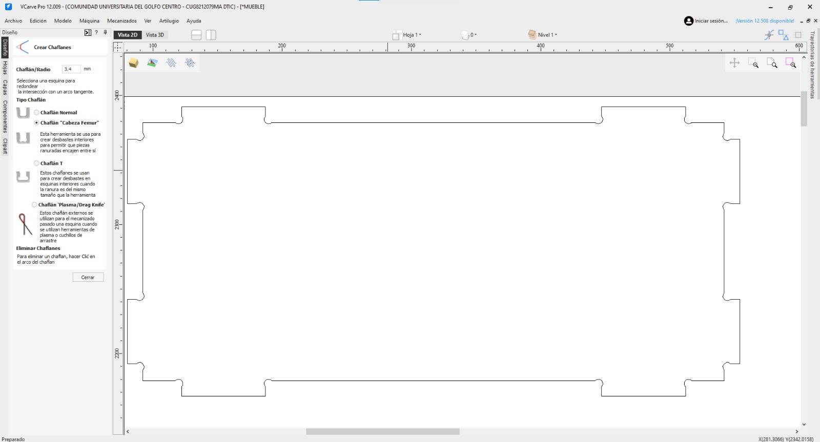
Dog-bones
To ensure parts fit together, we need "Dog-bones" for interior corners.
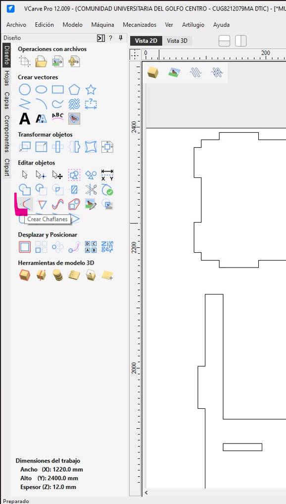
Fillet Tool
Select the "Dog-Bone Fillet" tool to start adjusting the joints.
Before
This is how the piece looks before applying the chamfer tool.
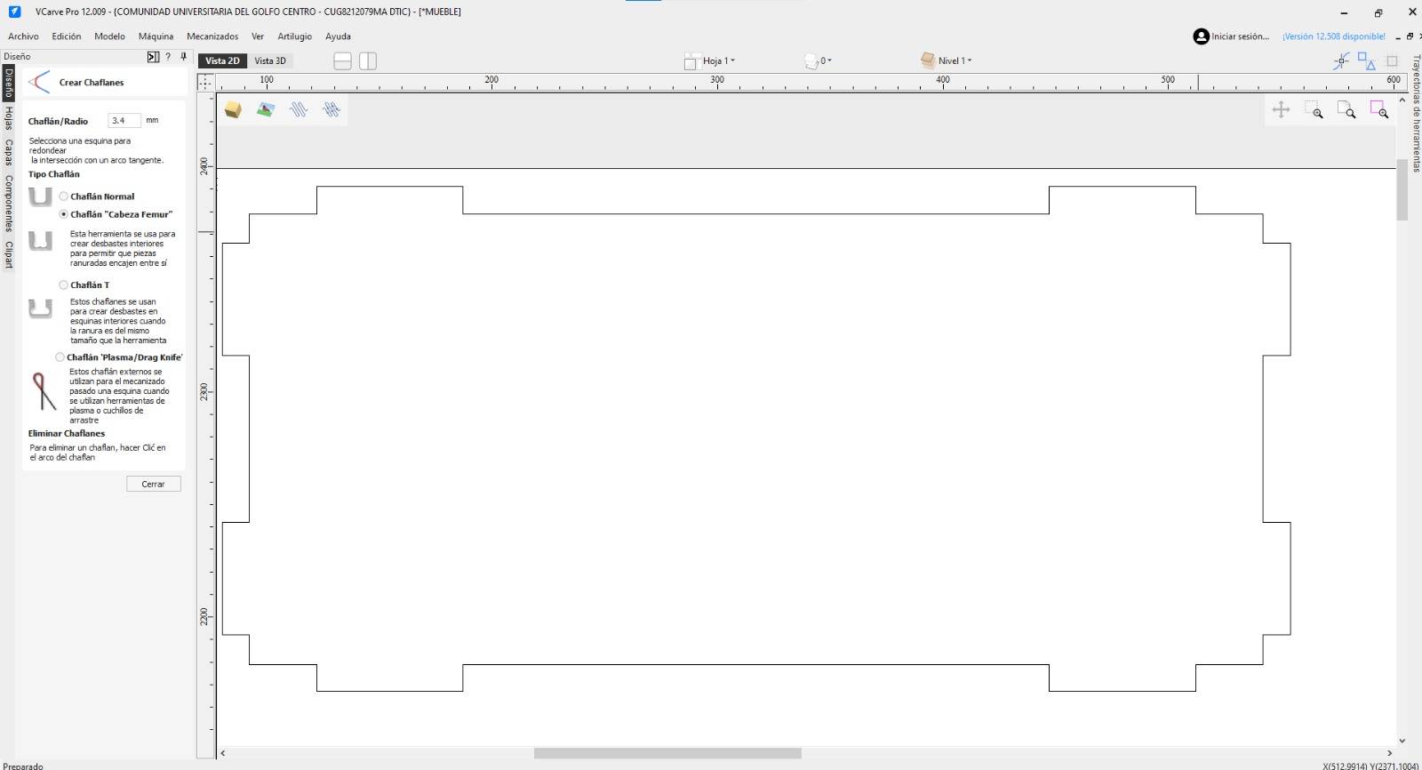
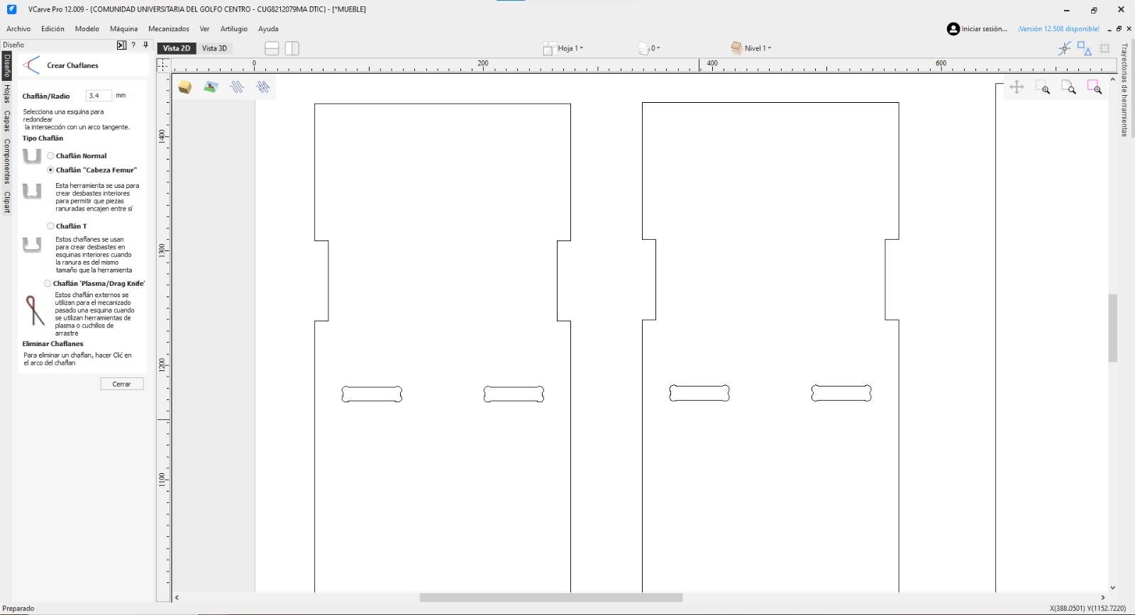
After
Click on the interior corners. Apply only to interior corners, not tabs.
Hole Dog-bones
For slots, apply the dog-bone fillet to all 4 corners.
Exterior Simulation
Now we simulate the exterior. Select all part contours. Since CNC bits are round, they cannot cut perfectly sharp 90° internal corners; they always leave a radius. Dog-bones create a small circular relief in the corners, allowing rectangular "tabs" or joints from other pieces to fit flush and lock together perfectly without manual sanding.
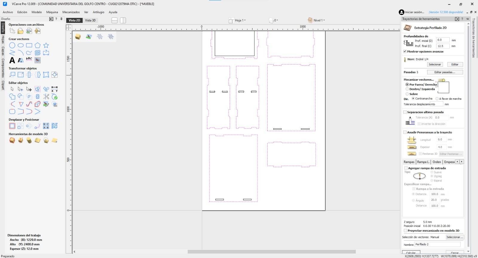
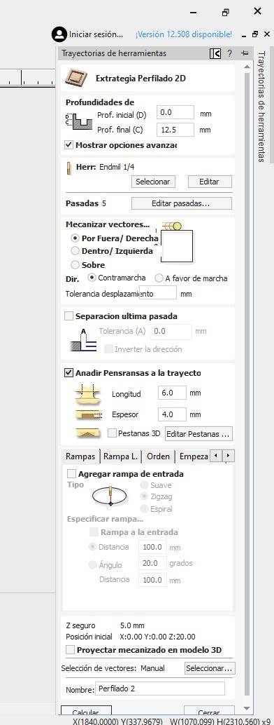
Exterior Profile
Select Outside/Right cut. Check "Add Tabs" and click "Edit Tabs".To keep the final piece at its intended size, the machine must cut on the Outside/Right of the vector. This ensures the waste material is removed from the exterior of the board, leaving your parts with the precise dimensions specified in your CAD design.
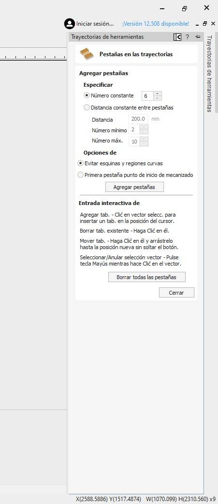
Manual Tabs
Tabs hold pieces in place, they are small bridges of material left intentionally between the part and the waste board. Without them, once the machine finishes the final pass of an exterior cut, the piece would become loose and could be sucked into the vacuum, hit the rotating bit, or fly off the table, damaging both the part and the machine. I used 6 tabs per part, placed manually on the contour.
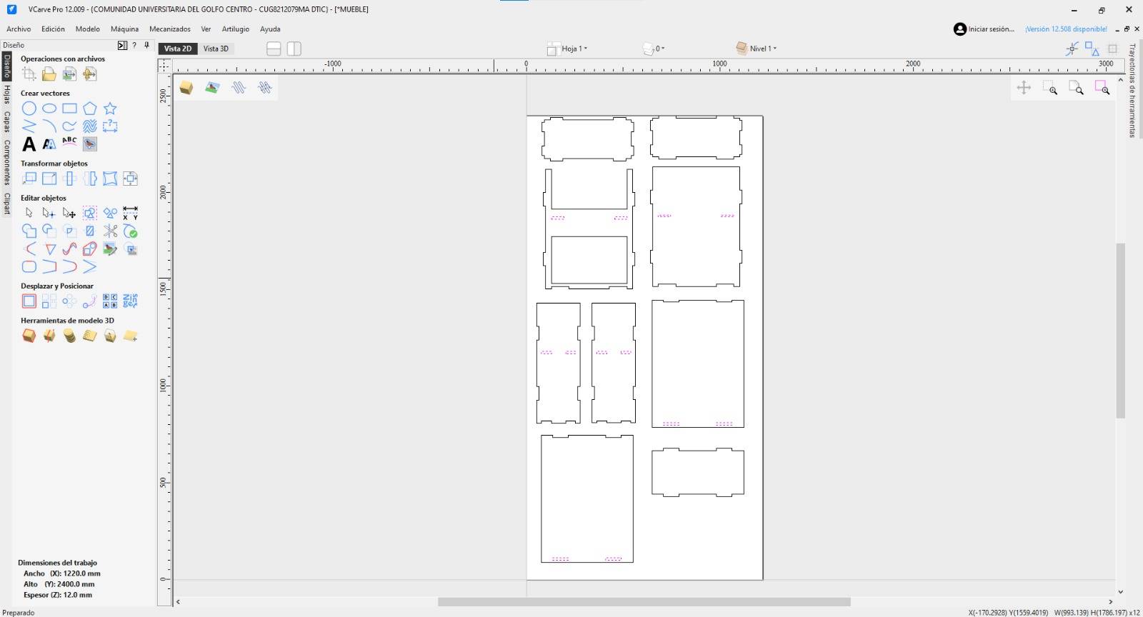
Tab Verification
Once tabs are added, your figures should look like the image below.
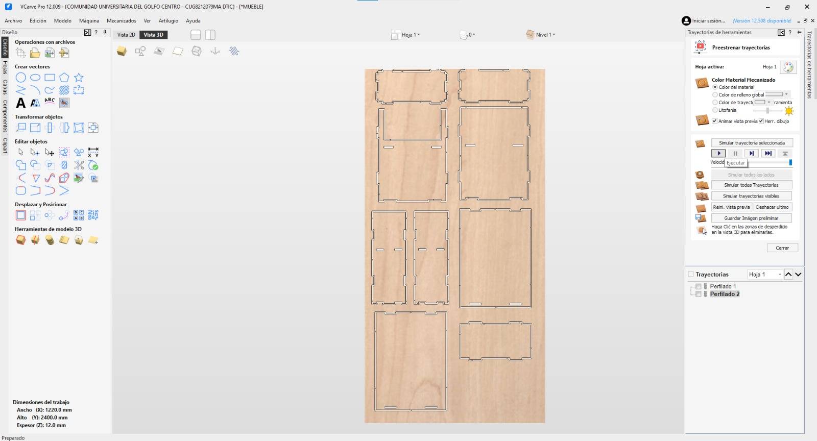
Full Simulation
Repeat the simulation process to see the final resulting cut.
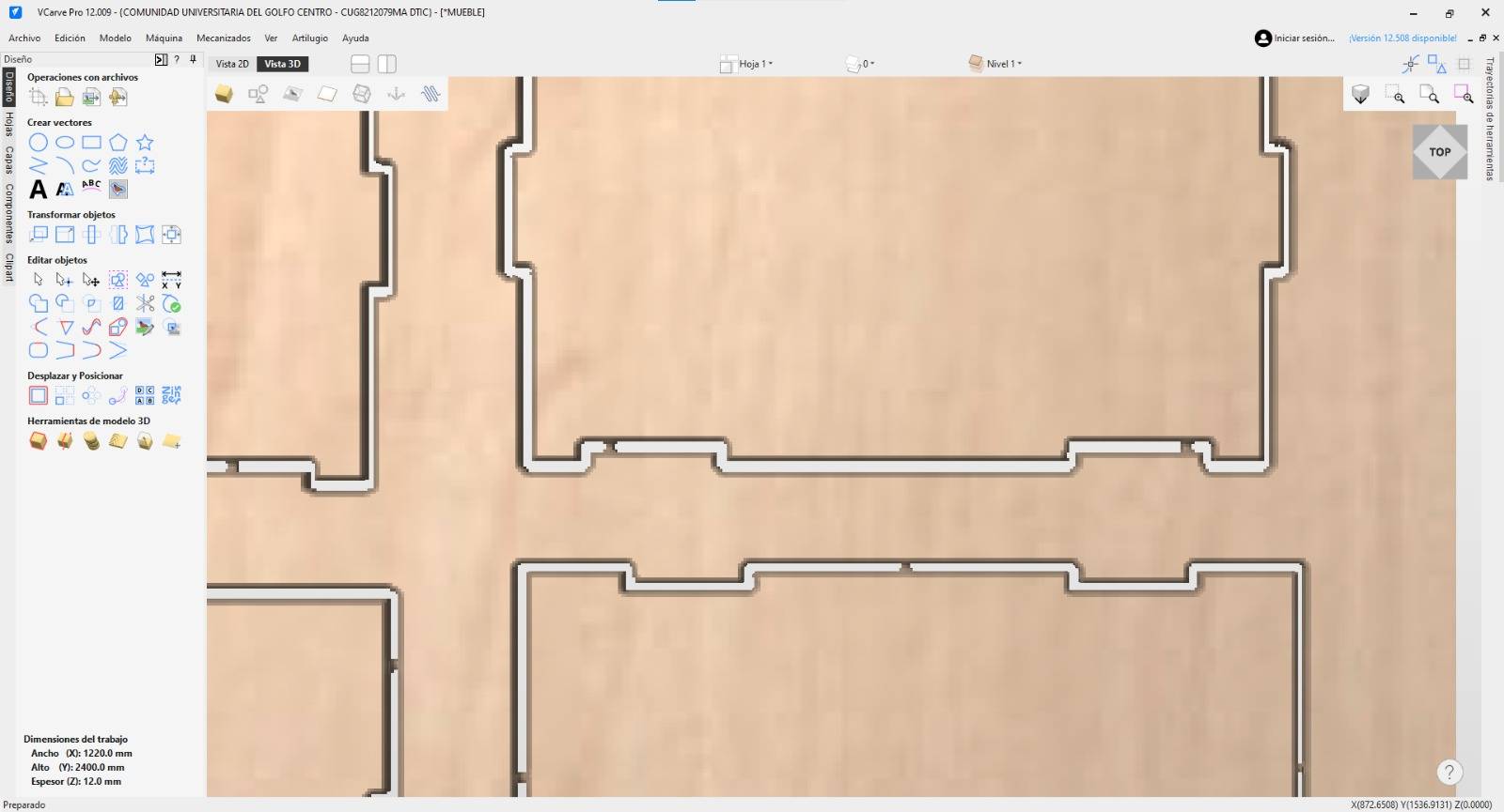
Zoom Tabs
Zoom in to verify the tabs are correctly placed and defined.
Save Path
Go to the main right menu and click the Floppy Disk icon to save.
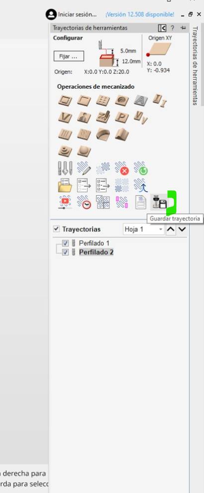
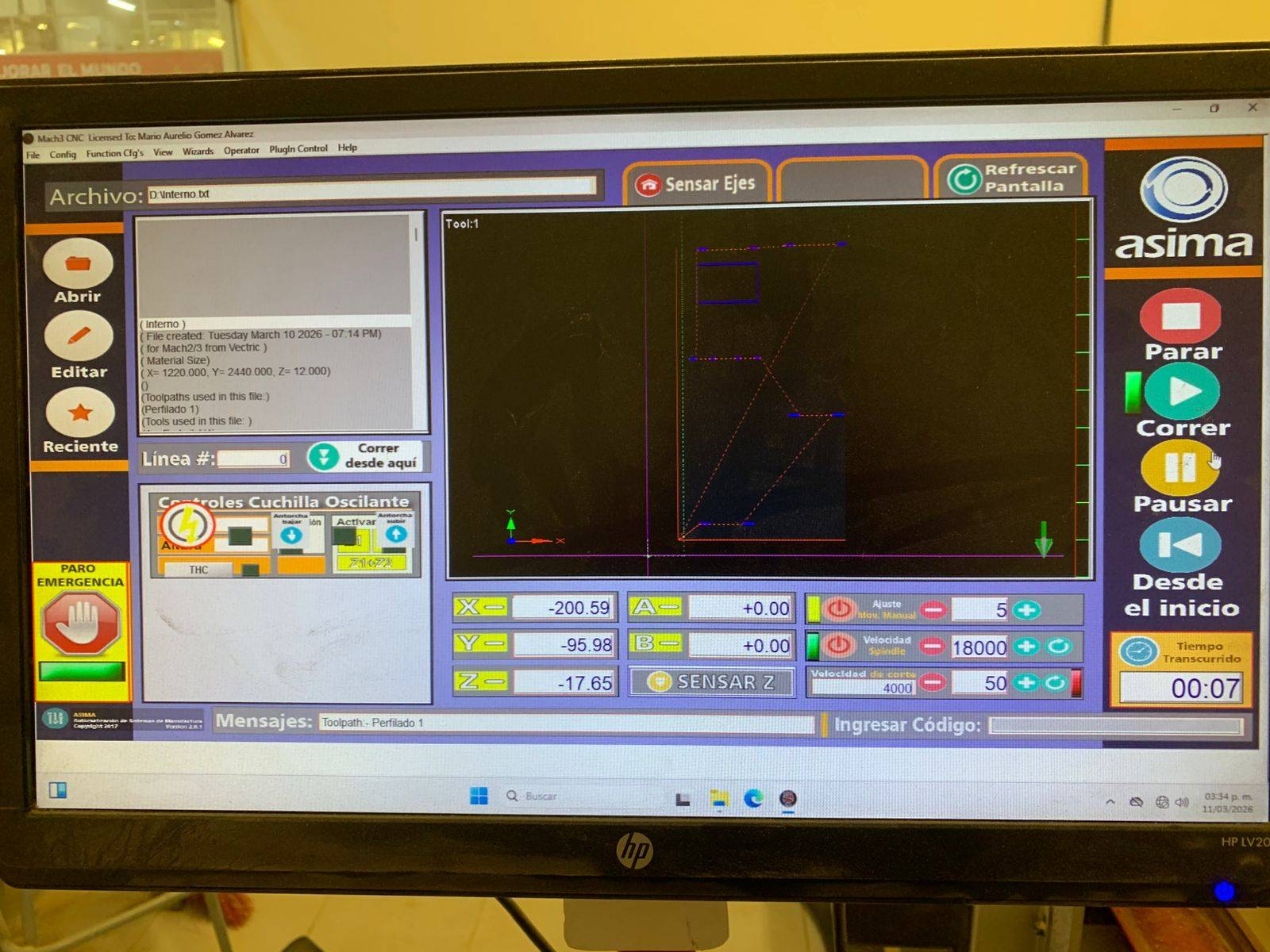
Post-processor
Select the correct Post-processor for your machine in the menu.
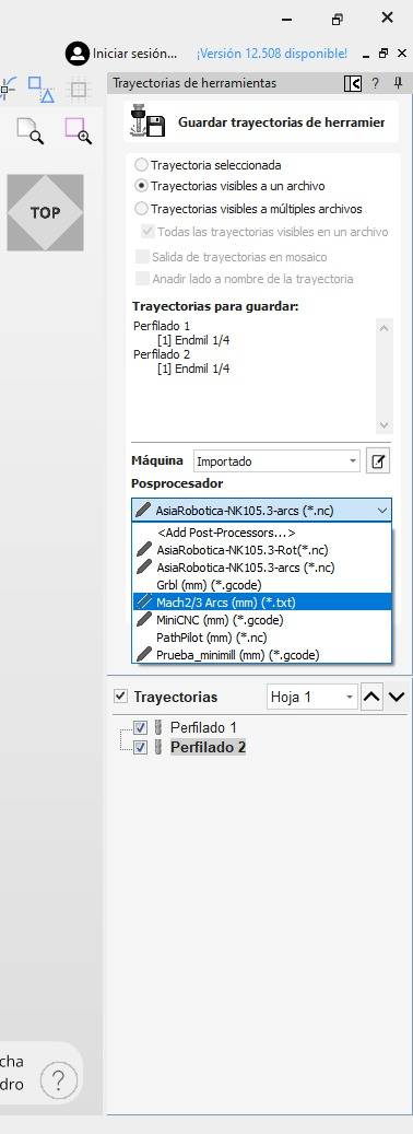
Verification
Verify that both internal and external cuts are selected in the output file.
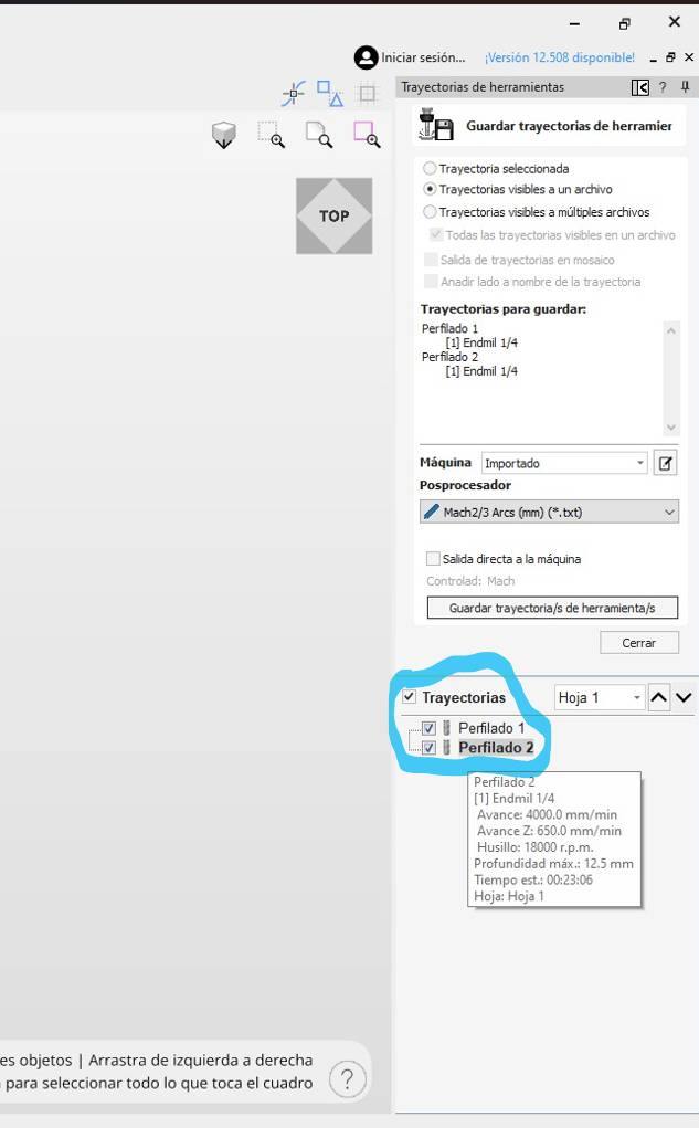
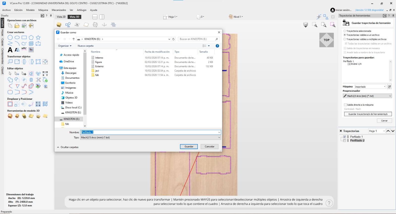
G-Code Export
Click "Save Toolpath" to export your final machining file.

Separate Saves
You can choose to save each toolpath as a separate file if preferred.
[ COMPARISON: CAD MODEL VS FINAL RESULT ]
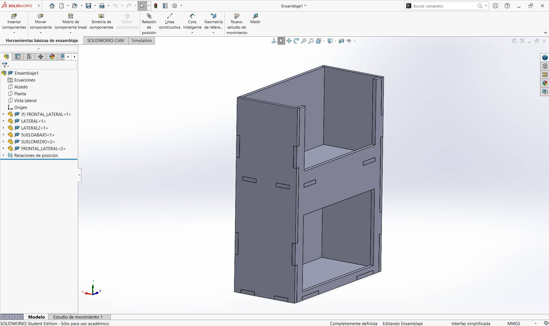
3D CAD Model
Diseño digital y ensamblado virtual en software.
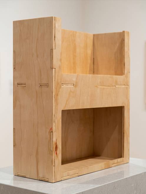
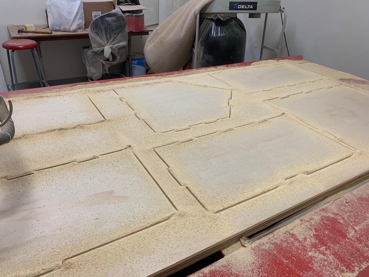
Final Result
Resultado físico tras el maquinado CNC.
[ ARCHIVE_DECRYPTED ]
Download the CNC files and assembly guides for this project.