Assigments

Foto de perfil

Week 6: Electronics Design
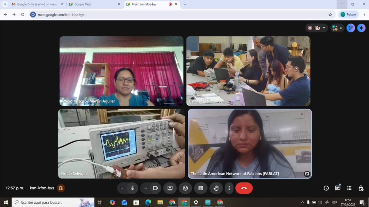
Group assignment:

  • Use the test equipment in your lab to observe the operation of a microcontroller circuit board (as a minimum, you should demonstrate the use of a logic analyzer)
  • Document your work on the group work page and reflect what you learned on your individual page

Individual assignments:

  • Use an EDA tool to design a development board that uses parts from the inventory to interact and communicate with an embedded microcontroller

Week 6 – Electronics Design

Week 6 – Electronics Design
Group Assignment

For the group assignment, I was in Madre de Dios, so I met virtually with my classmates. However, I also wanted to replicate everything that was done using the equipment available at the FAB LAB of IESTP Jorge Basadre Grohman, which is the only FAB LAB in the Madre de Dios region, so I document the work carried out.

What is a multimeter and what is it used for?

A multimeter is an electronic measuring instrument used to measure different electrical magnitudes in a circuit. It is a fundamental tool in electronics because it allows verifying whether a circuit works correctly, detecting faults and checking connections.

It is mainly used to measure:

  • Voltage (V) → electrical potential difference.
  • Current (A) → flow of electricity.
  • Resistance (Ω) → opposition to the flow of current.
  • Continuity → verify if a cable or connection is correct.
  • Diode and battery testing (in some models).

In projects with microcontrollers such as ESP32, the multimeter is used to check power supply, detect short circuits and measure current consumption.

Multimeter used

Brand / Model: SJE SJ-382
Type: Portable digital multimeter
Category: CAT II

General technical specifications

  • Digital LCD screen
  • Manual measurement with rotary selector
  • Fuse protection in the mA range
  • Powered by internal battery
  • Portable and lightweight
  • DC Voltage
  • AC Voltage
  • DC Current
  • Resistance
  • Continuity test
  • Diode test
  • Battery test (1.5V, 9V, 12V)
  • COM → black cable
  • VΩmA → normal measurements
  • 10A → measure high current

Img 1

a) Voltage measurement

First I connected the ESP32-C3 microcontroller to the computer via USB, then I set the multimeter to DC voltage and placed the black probe on GND of the ESP32 C3 and the red probe first on 5.0 V. Here a value of 5.07 V was obtained and then on 3V3 where a value of 3.26 V was obtained, which demonstrates that the board has a good power supply.

Img 2

Img 3

b) Continuity measurement

For this test I confirmed the common GND between sensors and the ESP32. To do this I disconnected the power supply, set the multimeter to continuity mode, placed the black probe on GND of the ESP32 and the red probe on GND of the buzzer and GND of the HC-SR04. To confirm continuity the multimeter emits a beep sound.

Img 4

Img 5

c) Searching for short circuits in rails

Without power connected I measured continuity between VCC and GND on the breadboard. The multimeter did not emit a beep which indicates that there are no short circuits, crossed cables, incorrectly used rails or wrongly placed jumpers.

Img 6

d) Voltage on the buzzer control pin

For this test the board was connected to the computer via USB. I set the multimeter to DC voltage, placed the black probe on GND of the ESP32 C3 and the red probe on the buzzer signal pin (not the power pin).

Buzzer OFF: 0V
Buzzer ON: 2.84 V

Img 7

What is an oscilloscope and what is it used for?

An oscilloscope is an electronic instrument that allows visualization of electrical signals over time. While a multimeter only shows a numerical value, the oscilloscope shows the waveform, which allows analyzing voltage over time, signal frequency, noise or interference, digital pulses, communication between devices and failures in electronic circuits.

Img 8

Oscilloscope verification using calibration signal

Before starting the tests the oscilloscope operation was verified using the calibration signal. This was done to confirm that the oscilloscope and the probe work correctly using the internal test signal of the instrument.

Img 9

Oscilloscope test on GPIO7 pin (buzzer)

For this test I used the circuit assembled in week 4. The objective was to verify with an oscilloscope whether the microcontroller is delivering a signal on GPIO7 that controls the buzzer and to observe its waveform.

Img 10 Probe tip not connected, the signal appears as a noisy line.

Img 11 Probe tip connected to GPIO7 showing PWM signal.

Img 12 Waveform observed.

Reflection

During the development of this group activity we understood the importance of correctly using electronic measurement instruments. The multimeter allowed us to verify basic circuit values such as voltage, continuity and ground connections, ensuring that the power supply and system connections were working correctly before performing more advanced tests.

The oscilloscope allowed us to observe the real behavior of electrical signals over time. Unlike the multimeter, which only shows average values, the oscilloscope allows visualization of the waveform generated by the microcontroller such as square signals or digital pulses. This confirmed that the GPIO pin was correctly generating the signal that controls the buzzer.

This activity helped reinforce knowledge about electronic measurement, signal interpretation and proper use of laboratory instruments, which are essential skills for analyzing and debugging electronic circuits.

II) Individual assignment

a. Use an EDA tool to design a development board that uses parts from the inventory to interact and communicate with an embedded microcontroller

EDA (Electronic Design Automation) refers to the set of software tools used to design, simulate, and document electronic circuits before their fabrication. These tools allow the creation of electrical schematics, the design of printed circuit boards (PCB), the verification of connections, and the preparation of the files necessary for board production. The use of EDA software is fundamental in the development of electronic systems because it reduces errors, facilitates the organization of components, and allows visualization of how the circuit will function before physically fabricating it.

KiCad is an open-source EDA software tool widely used for the design of electronic circuits and PCB boards. It allows the creation of electrical schematics, assignment of electronic components, generation of the physical board design, and production of the manufacturing files required for fabrication. KiCad is especially popular in open hardware and education projects because it is free, cross-platform, and has a wide library of electronic components, which facilitates the development of custom boards for microcontrollers and embedded systems.

To begin this task, the first step is to visit the KiCad website and download the program. Click here to access the website. KiCad - Schematic Capture & PCB Design Software

Img 13

Your operating system is selected, in my case it is Windows.

Img 14

I selected the GitHub option and the program started downloading immediately.

Img 15

I followed all the steps to complete the installation of KiCad.

Img 16

I started designing with KiCad, for this the tutorial video by Ulises helped me a lot. https://www.youtube.com/@fablabcodigo I started by creating a new project.

Img 17

Then I saved the project, I saved it as week 6.

Img 18

When saving, two folders appear (week 6.kicad_pcb and week 6.kicad_sch, which are PCB editor and Schematic editor respectively).

Img 19

Then I downloaded the footprint and symbol library, in my case I downloaded it from Adriano Torres' page https://fabacademy.org/2020/labs/leon/students/adrian-torres/fabxiao.html#datasheetESP

Img 20

After entering the link https://gitlab.fabcloud.org/pub/libraries/electronics/kicad I selected Code and downloaded the zip.

Img 21

Then I added the symbol and footprint libraries.

Img 22

Img 23

Img 24

Then we started to create the schematic of the board, for this the symbols with their respective footprints must be added. In my case I assigned the symbols from the FAB library.

Img 25

We added the symbols, this took a while.

Img 26

Then we started by adding the symbol with its respective footprint of the microcontroller that we will use, which will be the XIAO ESP32-C3. This is found in the FAB library.

Img 27

Then we added the other electronic components considering that the input and output pins that will connect to the XIAO are not repeated.

Img 28

Then we added labels to maintain order and know what will be connected with what.

Img 29

We continued adding all the components and naming them. We also added a LED and a push button to interact with the board and observe connections and signals. Once the schematic was finished we added the footprints.

Img 30

Img 31

Then we updated the PCB with the components from the schematic.

Img 32

Then the schematic is updated for the PCB.

Img 33

We carried out the routing of traces establishing the width, giving them a width of 15 mils (0.381 mm). This is a width commonly used in PCB for low-power signals (digital and analog).

Did you have any problems?

Yes, since we were initially working on the top layer, I did not realize that the footprints and traces should have been on the bottom layer, because the components were through-hole and everything would be soldered on the bottom layer. Therefore I had to correct that.

Img 34

Img 35

Img 36

Then I created my board design in the shape of a heart, well I tried.

Img 37

Then I added the 3D model library to visualize my board in 3D. I added each electronic component one by one by double-clicking the component and selecting the corresponding library, rotating and scaling as necessary.

Img 38

Why is it possible to fabricate my board?

The board design was developed using KiCad, an open-source EDA tool widely used for the design of electronic circuits and printed circuit boards. In this tool, I created both the circuit schematic and the PCB design, which made it possible to verify the electrical connections between the components and correctly organize their distribution on the board.

The designed board uses the XIAO ESP32-C3 as its main element, which acts as the central microcontroller of the system. From this module, different pins are distributed to external connectors that will allow the connection of sensors and actuators, such as I2C communication buses, analog and digital signals, as well as 3.3V, 5V, and GND power supply. Basic interaction and diagnostic components such as indicator LEDs, current-limiting resistors, and a tactile push button were also incorporated, which will make it easier to verify the operation of the board during testing.

The design was created considering the fabrication capabilities available in the laboratory, particularly PCB milling. The traces were organized respecting the basic design rules, avoiding unnecessary crossings and maintaining a clear distribution of the components around the microcontroller. Likewise, the design includes pin header connectors that allow external modules to be connected without the need for complex soldering.

Thanks to the use of KiCad, it was also possible to visualize the 3D model of the board, which made it possible to verify the physical position of the components and ensure that all elements fit correctly before fabrication. This reduces errors during assembly and confirms that the design is physically feasible.

Altogether, these aspects demonstrate that the design is ready for fabrication and aligned with the tools, materials, and processes available in the laboratory.

Problems I had and how I solved them

One of the main challenges during the development of the design was that I was still in an initial stage of learning electronics. At the beginning, understanding the process of circuit design and the organization of the components in the schematic was a bit complex, which made the design stage take more time than expected.

To improve my understanding of the process, I reviewed Ulises' recorded class again, which helped me reinforce important concepts and observe practical examples of the use of design tools. In addition, I had the support of Ronald, who provided guidance during the process and explained several aspects of the design that I did not initially understand clearly.

Thanks to this combination of reviewing the class material, practice, and support, I was able to better understand the logic of the circuits, the pin assignment of the microcontroller, and the correct way to organize the components within the schematic. This allowed me to overcome the initial difficulties and complete the board design.

Reflections

Installing KiCad was one of the first important steps in the development process. Although it is a very complete software, its installation and configuration did not present major difficulties thanks to the availability of documentation and online resources. This allowed me to quickly start the circuit design and become familiar with the program tools.

The learning process during the classes was very enriching. In particular, Ulises' explanation about the use of KiCad and the organization of circuits helped me understand not only how the software works, but also good practices for the design of electronic boards. His examples and recommendations made the learning process easier and allowed me to apply this knowledge directly in the development of the project.

The creation of the board design was a challenging but very rewarding experience. At first, it was necessary to spend time understanding how to organize the connections and correctly place the components. However, as the process progressed, it became clearer how to structure the circuit and how to distribute the elements on the PCB to optimize space and facilitate the routing of the traces.

The use of the 3D PCB visualization was also very useful for understanding how the board would look physically once fabricated. This made it possible to verify the location of the connectors, the microcontroller, and the electronic components, ensuring that the design was functional and practical.

In general, this project allowed me to develop important skills in electronic circuit design and in the use of EDA tools. In addition, it strengthened my understanding of the complete process of creating an electronic board, from schematic design to preparation for fabrication.