Document your work on the group work page and reflect on your individual page what you learned.
Individual assignment:
Write an application for the embedded board that you made, that interfaces a user with an input and/or output device(s).
I) Group Assignment
1. Compare as many tool options as possible
The group work was developed at Universidad del Pacífico. For this activity, we evaluated each interface development tool based on key parameters such as the type of communication, the protocol used, the target device, complexity, and specific use cases.
XIAO ESP32-C3: Used as the main microcontroller. It processes data from sensors and enables communication with external systems such as web applications or databases.
HC-SR04: Ultrasonic sensor used as an input device. It measures distance and sends data to the microcontroller.
LED: Output device used to visualize system responses. It turns ON or OFF depending on the commands or sensor conditions.
PuTTY: Software used for serial communication. It allows monitoring and debugging data sent from the microcontroller through the serial port.
Processing: A programming environment used to create graphical user interfaces (GUI). It enables visualization of sensor data in a more interactive and dynamic way.
RemoteXY: A platform used to create WiFi-based interfaces. It allows controlling the microcontroller remotely through a mobile device using a custom interface.
MIT App Inventor: Tool used to develop mobile applications with Bluetooth communication. It enables interaction between a smartphone and the microcontroller without requiring advanced programming.
a) Serial Interface (PuTTY)
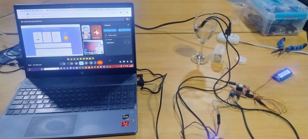
In this practice, communication was established between the XIAO ESP32-C3, the HC-SR04 sensor, and an external software tool (PuTTY) through serial communication, allowing real-time data visualization.
The objective was to achieve interaction between a microcontroller, an input sensor, and an external software interface in order to visualize measurements in real time.
PuTTY is free software that allows serial communication with microcontrollers through a COM port, functioning as an alternative to the Arduino Serial Monitor.
Workflow
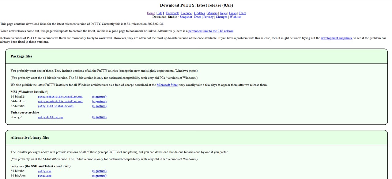
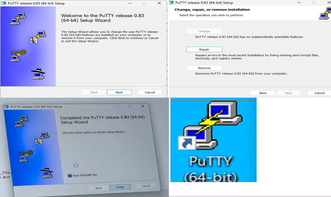
Installation: PuTTY was downloaded and installed from its official download site, selecting the correct characteristics for the computer.
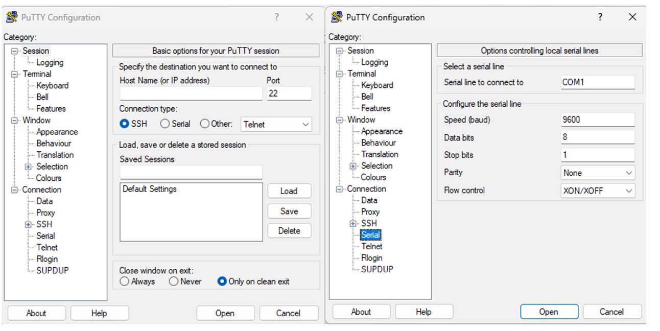
Configuration: The serial connection was configured using the corresponding COM port and a baud rate of 115200.
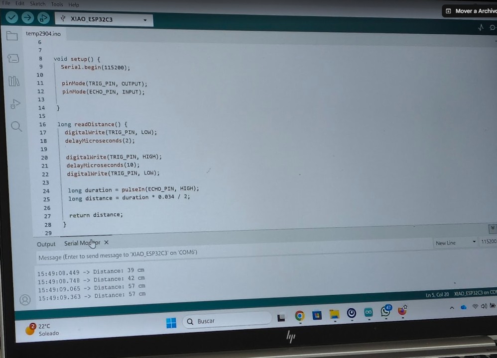
Programming: Arduino code was used to activate the HC-SR04 sensor, calculate distance, and send data through serial communication.
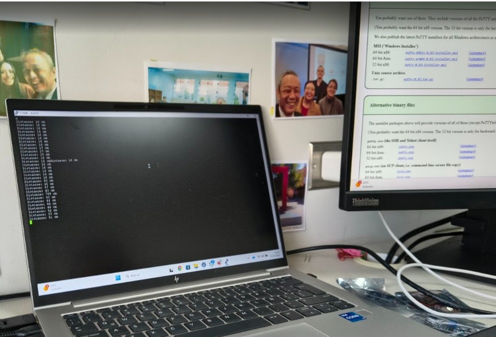
Validation: The system was first validated with the Arduino Serial Monitor. Then PuTTY was opened and the same real-time information was observed through the serial port.
Img. 4: The system was first validated with the Arduino Serial Monitor.
Img. 5: PuTTY was opened and the same real-time information was observed through the serial port.
Learning
Serial communication is the basis for connecting hardware with software.
PuTTY can function as an external interface to visualize data.
This type of interface is the first step before developing more advanced interfaces such as web applications or mobile apps.
Conclusion
A basic functional interface was implemented between the microcontroller and external software, demonstrating how sensor data can be sent and visualized in real time.
b) Graphical Interface (Processing)
In this practice, a graphical interface was developed in Processing to control an LED connected to the XIAO ESP32-C3 through serial communication. The interface allows commands to be sent from the computer to the microcontroller in real time.
Processing is a programming environment oriented toward the creation of interactive graphical interfaces, very useful for visualizing data and controlling electronic systems.
Workflow
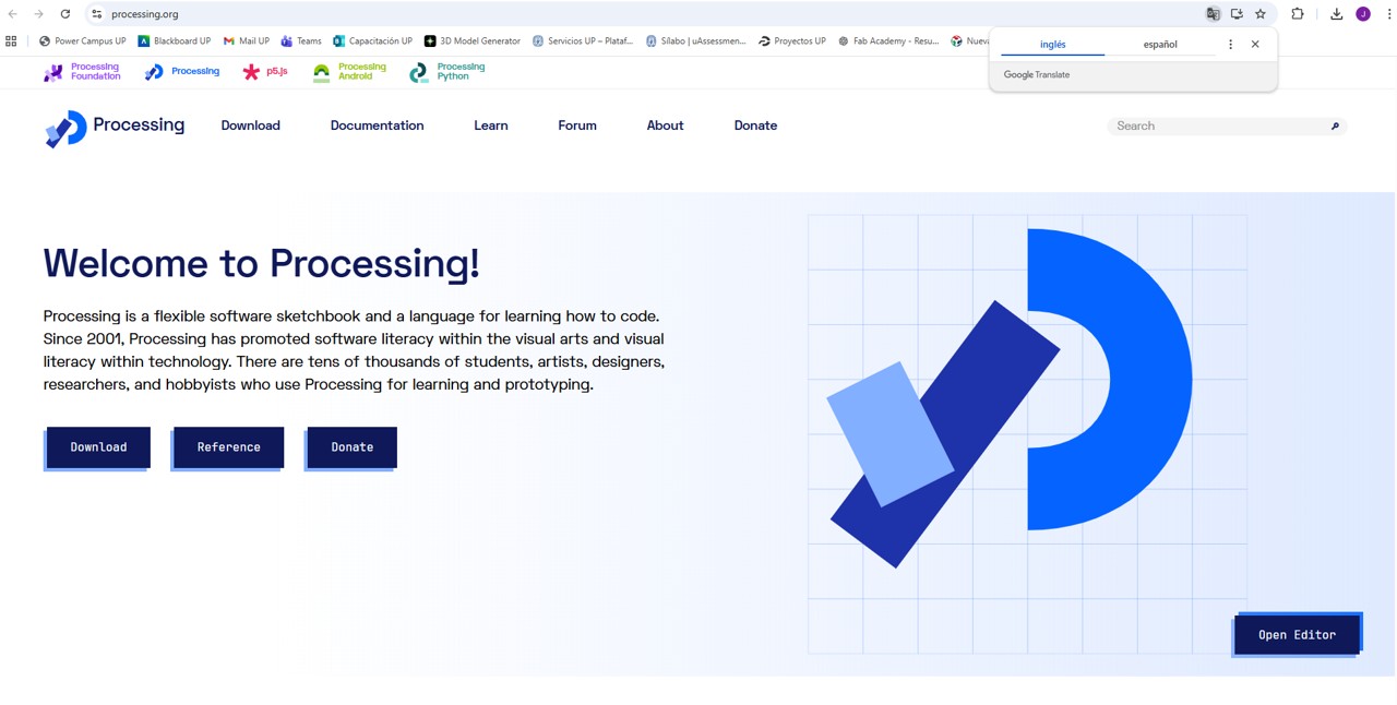
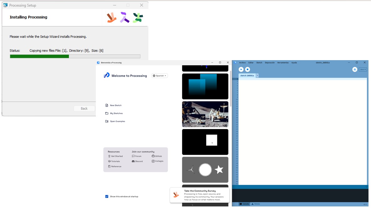
Installation: Processing was downloaded from its official page and executed without requiring a complex installation process.
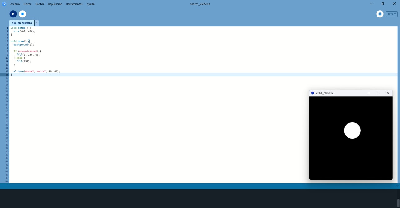
Initial exploration: Basic tests were performed to understand setup() as the initial configuration and draw() as the continuous execution function.
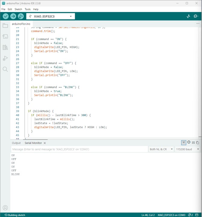
Arduino programming: The microcontroller was programmed to receive serial commands such as “ON”, “OFF”, and “BLINK”, and to control the LED connected to pin D6.
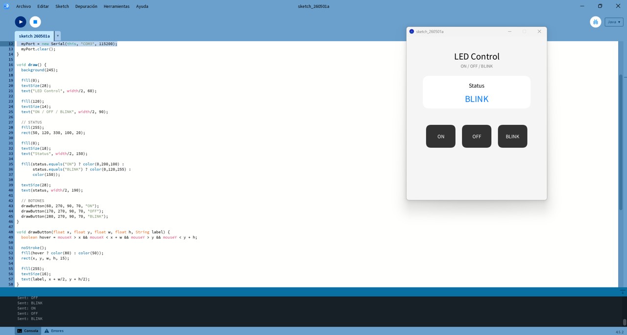
Processing interface: An interface was developed with interactive buttons (ON, OFF, BLINK) and a LED status indicator.
Img. 6: Processing was downloaded from its official page.
Img. 7: Processing was executed without requiring a complex installation process.
Img. 8: Basic tests were performed to understand setup() and draw().
Img. 9: The microcontroller was programmed to receive serial commands and control the LED connected to pin D6.
Img. 10: Interface developed with interactive buttons and a LED status indicator.
Learning
A graphical interface can control hardware through serial communication.
Processing facilitates the creation of interactive interfaces.
The workflow user → software → hardware is fundamental in embedded systems.
Problems encountered
Serial port conflict: The Arduino Serial Monitor had to be closed before using Processing.
Incorrect LED pin: The configuration was corrected to pin D6.
Conclusion
A graphical interface was successfully integrated with an embedded system, allowing real-time control of a physical device through user interaction.
c) WiFi Interface (RemoteXY)
In this practice, a wireless mobile interface was developed using the RemoteXY platform, allowing control of the XIAO ESP32-C3 board through WiFi communication. The interface was visually designed and the code was automatically generated by the platform.
This is a wireless interface where the user interacts from a mobile device, the communication is performed through WiFi, and the microcontroller responds in real time.
Workflow
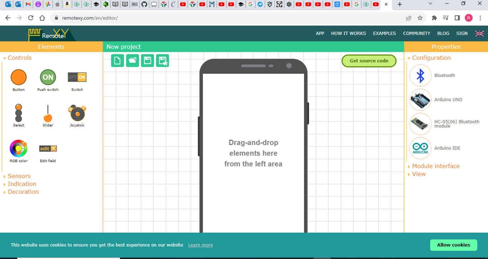
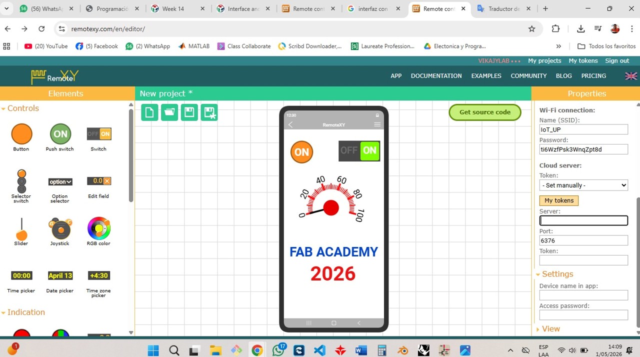
Access to the editor: The RemoteXY web editor was accessed to design the interface in the cloud.
Project configuration: The main parameters were defined: WiFi connection in access point mode, XIAO ESP32-C3 board, integrated WiFi communication, baud rate 115200, SSID, and password.
Interface design: Graphical components such as switches, buttons, indicators, and text labels were added and organized intuitively for the user.
Verification: Each component was connected to internal variables, and RemoteXY automatically generated the Arduino code.
Img. 11: RemoteXY web editor used to design the interface in the cloud.
Img. 12: Interface design with switches, buttons, indicators, and labels.
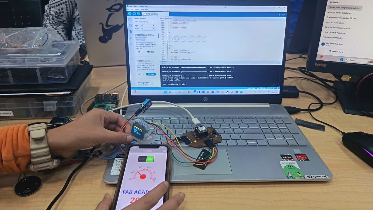
Img. 13: After connecting the mobile device to the network created by the ESP32, the interface was accessed and the board responded in real time.
Learning
It is possible to control hardware wirelessly.
Mobile interfaces facilitate interaction with embedded systems.
RemoteXY simplifies development by automatically generating code.
Conclusion
A functional WiFi interface was implemented, allowing the system to be controlled remotely and demonstrating a more advanced and intuitive form of interaction between the user and the hardware.
d) Mobile Application (MIT App Inventor)
MIT App Inventor is a free platform that allows mobile applications to be created through visual block programming, without the need to write complex code.
In this practice, a custom mobile application was developed using MIT App Inventor, allowing an ESP32 to be controlled through Bluetooth communication. The application was visually designed using blocks, facilitating interaction between the user and the hardware.
Workflow
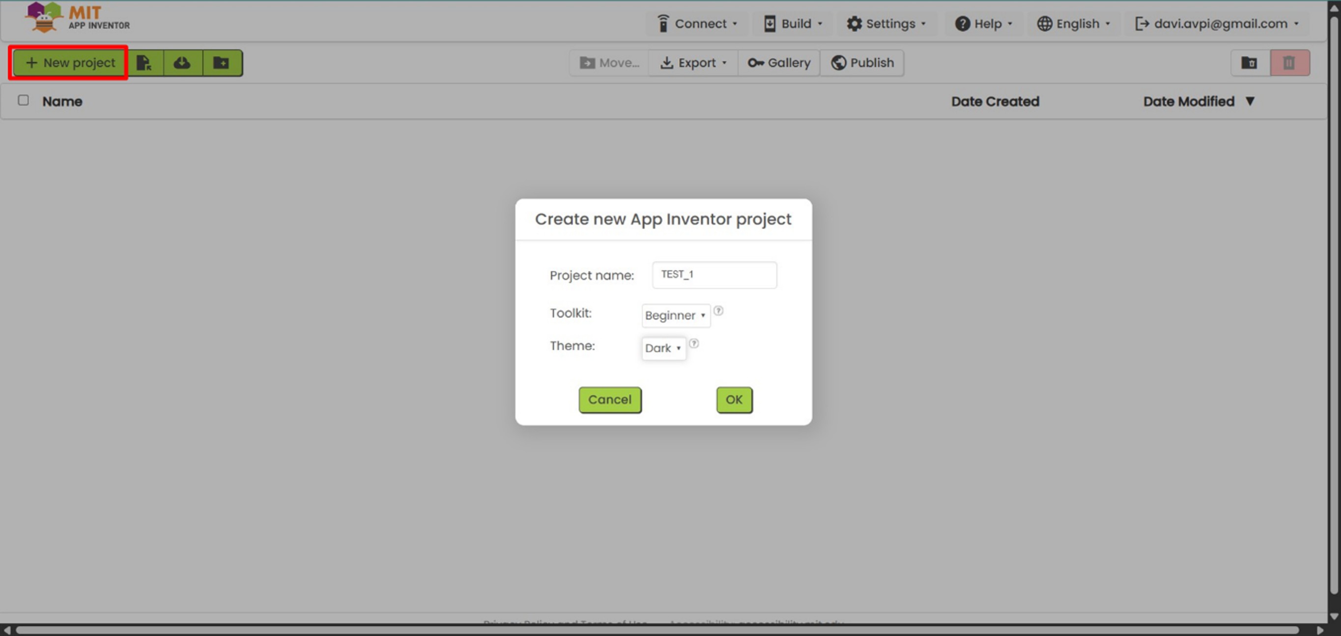
Project creation: The official App Inventor website was accessed, a new project was created, and the basic properties of the application were configured.
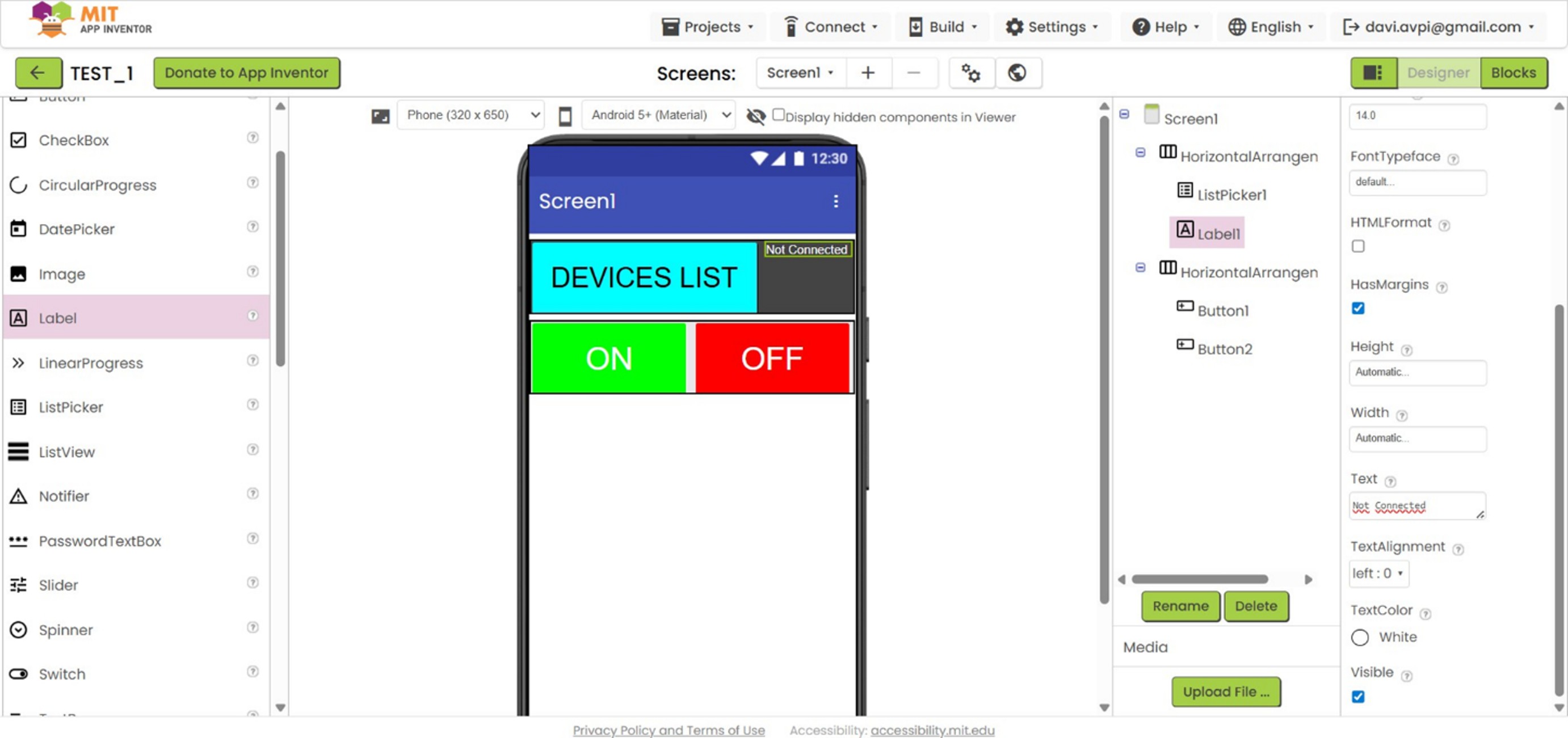
Interface design: Components such as buttons, design containers, a Bluetooth device selector (ListPicker), text, and images were added.
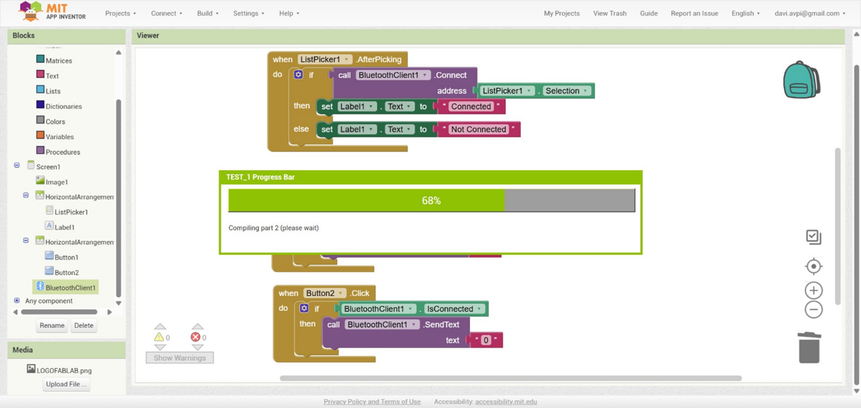
Block programming: The logic was configured to show available Bluetooth devices, establish connection with the ESP32, send commands (“1” and “0”), generate the APK file, and install it on the mobile device using a QR code.
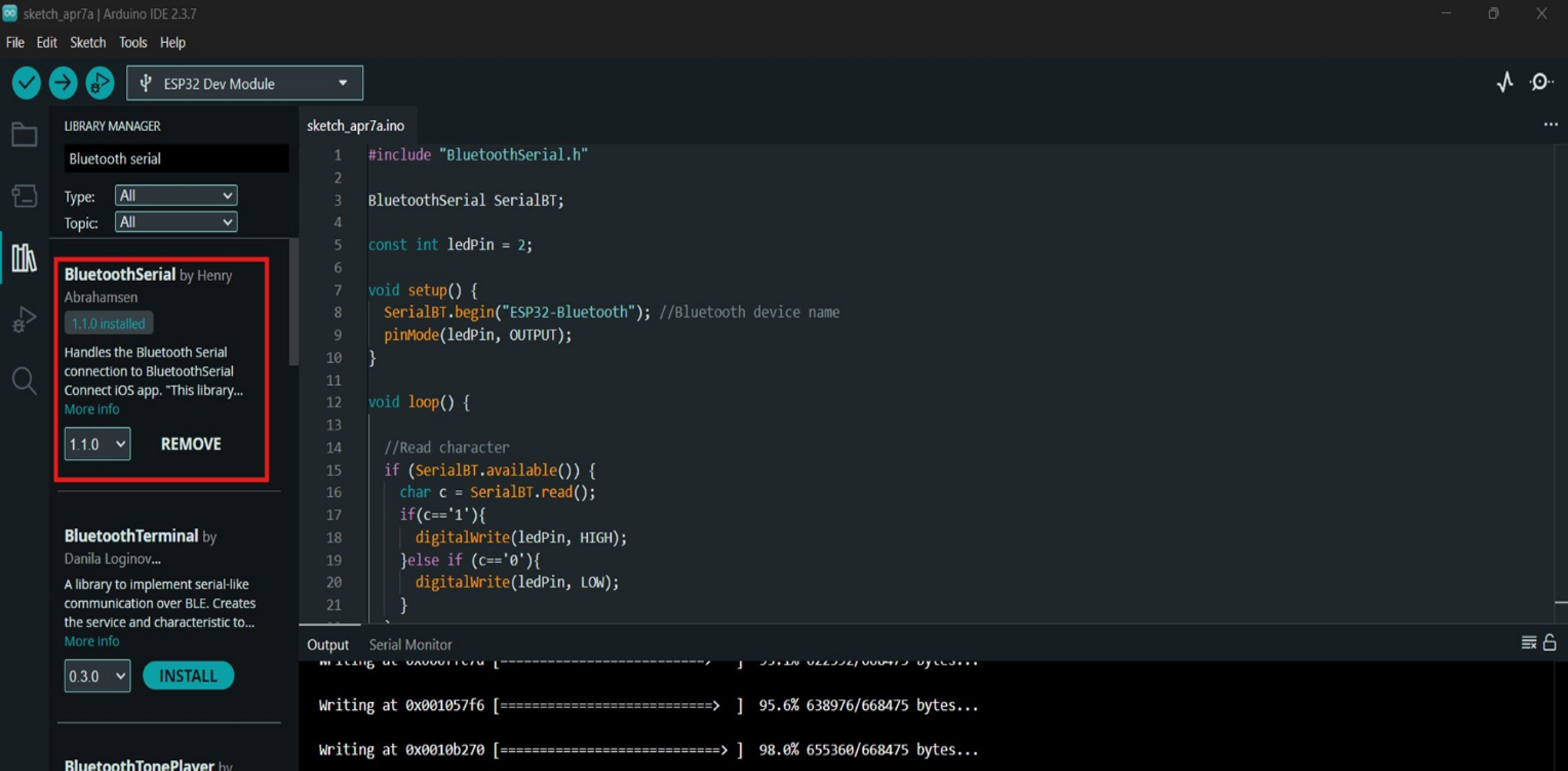
ESP32 programming: The microcontroller was programmed to receive data through Bluetooth Serial and turn an LED on or off according to the received command.
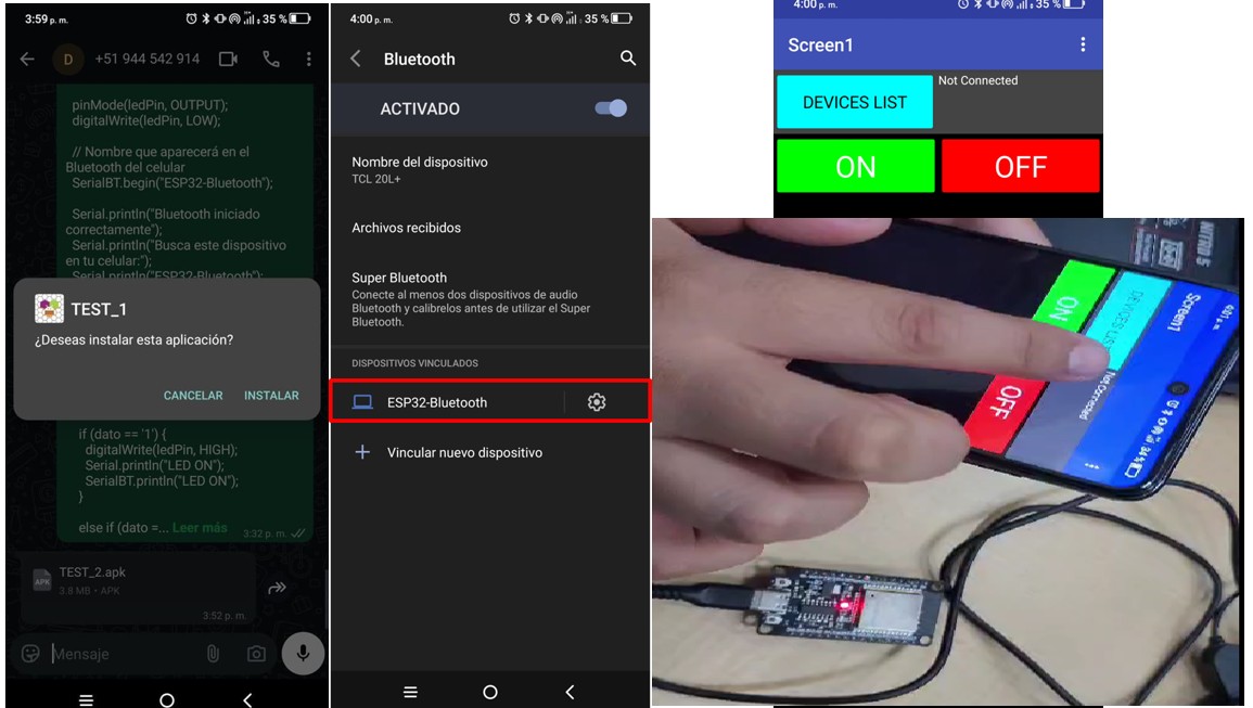
System execution: The user connects the phone to the ESP32, selects the device in the app, presses the buttons, and the LED responds in real time.
Img. 14: Access to the official App Inventor website.
Img. 15: A new project was created and the basic properties of the application were configured.
Img. 16: Interface design with buttons, containers, Bluetooth device selector, text, and images.
Img. 17: Block programming to connect with the ESP32 and send commands.
Img. 18: ESP32 programming to receive Bluetooth Serial data and control an LED.
Img. 19: System execution: the phone connects to the ESP32 and the LED responds in real time.
Learning
It is possible to create mobile applications without complex programming.
Bluetooth communication allows direct interaction with hardware.
Mobile interfaces are intuitive and easy to use.
Conclusion
A functional mobile application was developed to control an embedded system through Bluetooth, demonstrating a practical and accessible way to interact between the user and the microcontroller.
General reflection – Group work
During the development of the group work, we explored different interface and communication tools: PuTTY, Processing, RemoteXY, and MIT App Inventor, each representing a different way of interacting between the user and an embedded system.
This process allowed us to understand that there is not only one way to create interfaces, but multiple approaches depending on the level of complexity, the type of communication, and the user experience that we want to achieve.
For example, PuTTY allowed us to understand the basis of serial communication, being a fundamental tool for debugging and initial tests. Then, with Processing, we moved toward desktop graphical interfaces, achieving a more visual and friendly interaction. Later, with RemoteXY, we explored wireless communication through WiFi, facilitating remote control without wiring. Finally, with MIT App Inventor, we developed a mobile application using Bluetooth, approaching more real and practical solutions for the end user.
Through this comparison, we understood how each tool responds to different needs:
simple interfaces for debugging
graphical interfaces for visualization
wireless interfaces for remote control
mobile applications for direct interaction
In addition, this work reinforced our understanding of different communication protocols (serial, WiFi, and Bluetooth) and their application in embedded systems.
Overall, this experience allowed us to build a comprehensive vision of interface development, understanding that the choice of the appropriate tool depends on the project context, available resources, and the type of end user.
II) Individual Assignment
1. General description
This week I developed a web application connected to Firebase Realtime Database, which allows real-time visualization of the data obtained from my embedded board, the XIAO ESP32-C3, as well as interaction with the system through remote control.
The system integrates physical sensors with a digital interface, achieving bidirectional communication between the user and the device.
2. What is Firebase?
Firebase is an application development platform created by Google that allows web and mobile applications to be built quickly, especially those that require real-time data. Within its services, I used Firebase Realtime Database, which is a cloud database that stores data in JSON format, synchronizes information in real time, allows multiple devices to access the data simultaneously, and automatically updates the interface without needing to reload the page.
Firebase functions as a communication bridge between hardware and software. It allows:
the ESP32 board to send sensor data
the web application to read this data in real time
the user to send commands from the web interface to the board
3. Firebase installation and configuration steps
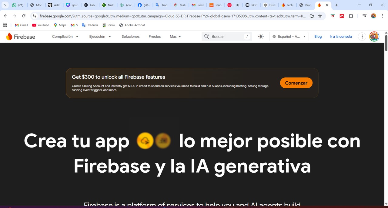
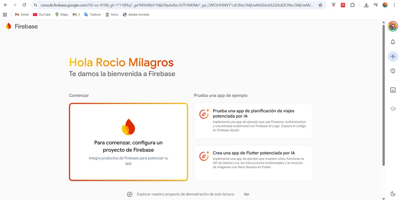
To install Firebase, I entered the following link: Firebase official website, or Firebase can also be searched directly on Google.
Img. 20: Access to the Firebase official website.
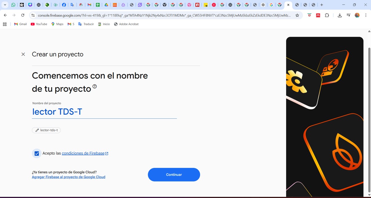
Img. 21: Firebase project configuration.
Img. 22: The project was named “lector TDS-T” for the readings of total dissolved solids and temperature of my final project.
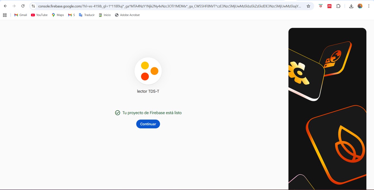
Img. 23: Continue project configuration.
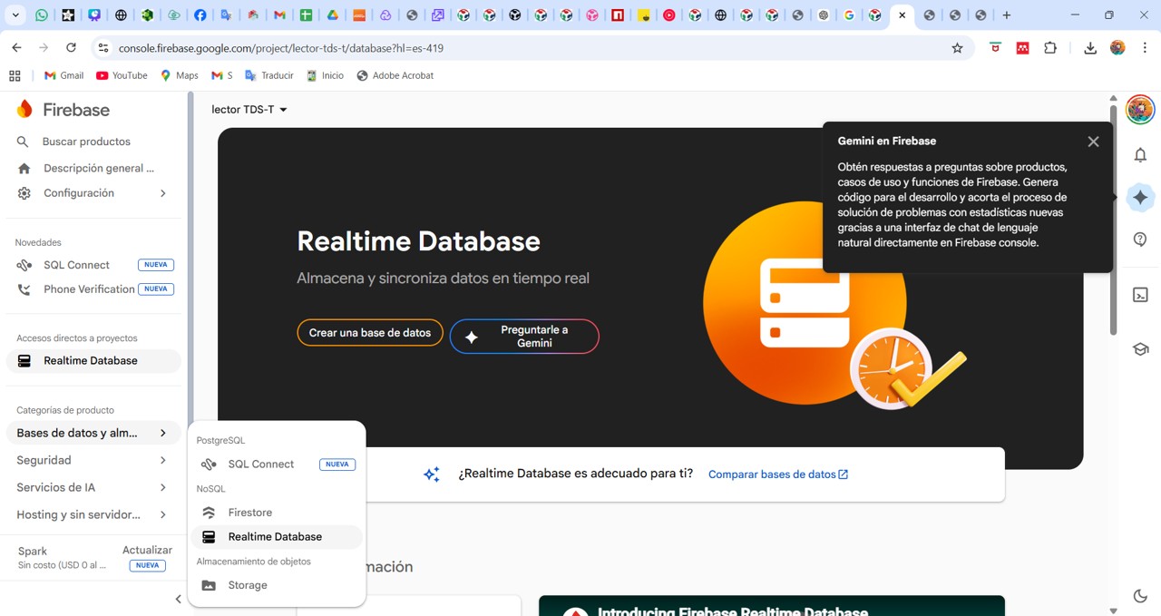
Img. 24: Realtime Database was selected.
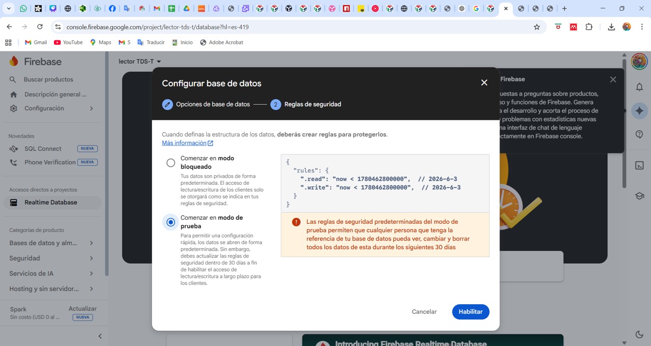
Img. 25: Test mode was started and enabled.
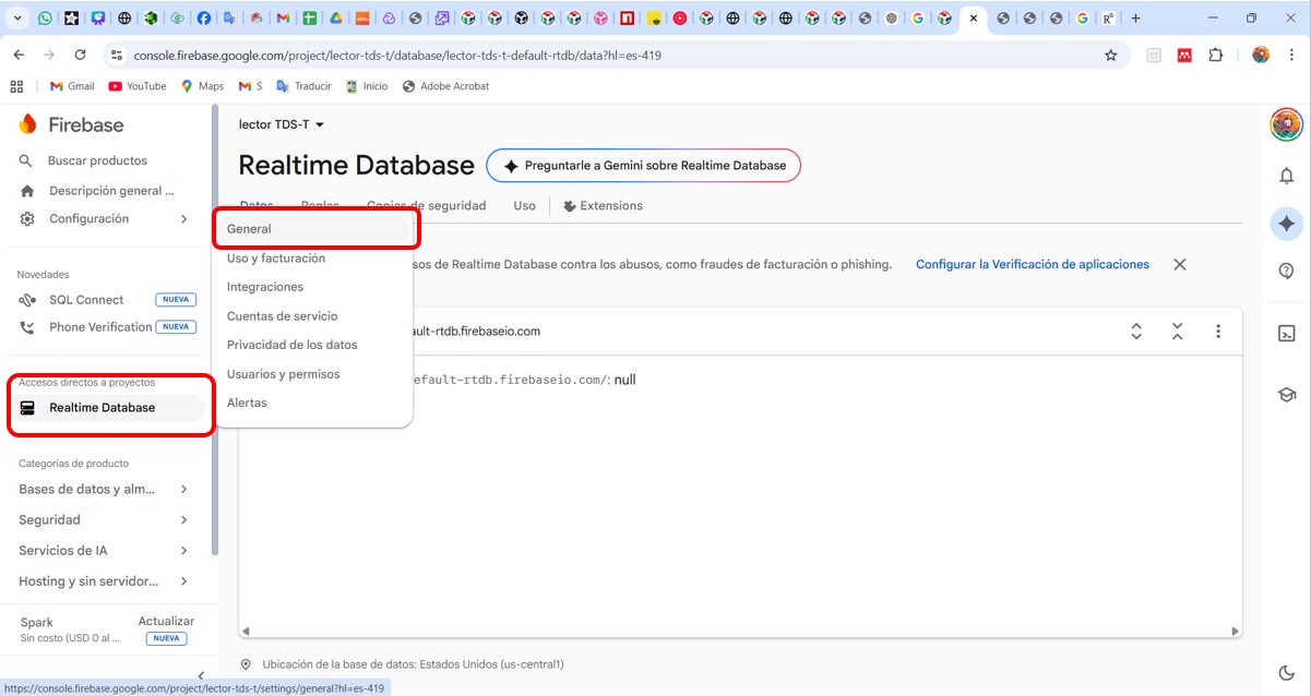
Img. 26: General project settings.
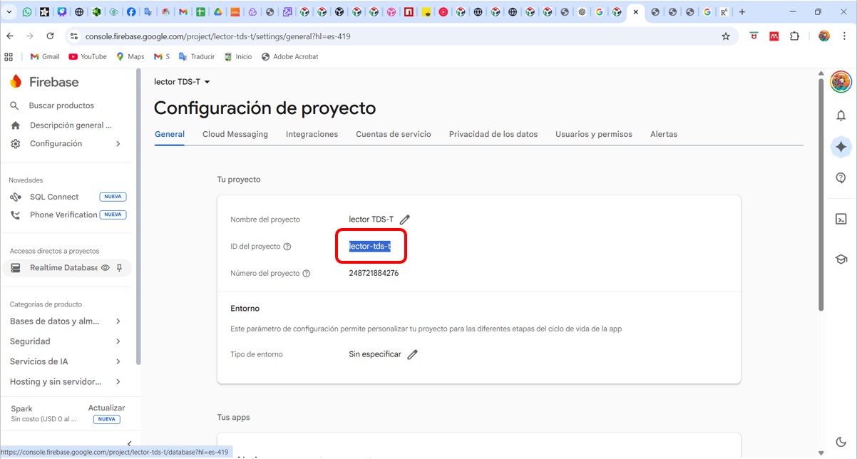
Img. 27: Project ID copied from Firebase.
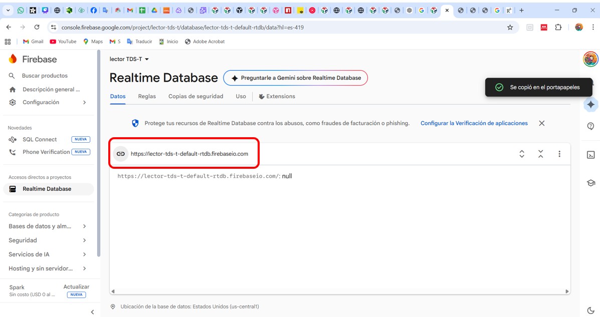
Img. 28: Link generated by Firebase.
4. System workflow
The system works according to the following flow:
Sensors (TDS + Temperature) → XIAO ESP32-C3 → Firebase Realtime Database → Web Application (HTML + JavaScript) → User visualizes and controls the system
5. Step-by-step workflow description
1. Data capture
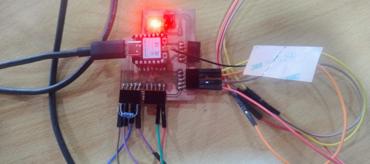
For this part, I used my board with the input and output sensors developed in Week 10: Week 10 documentation.
The following components were used: DS18B20 temperature sensor, Gravity TDS V1.0 water quality sensor, LCD, and LEDs on the board.
Img. 29: The ESP32 board performs temperature reading, analog TDS reading, ppm calculation, and data sending to Firebase.
2. Arduino code generation
For code generation, I used ChatGPT and the support of my friend Jair, who is a systems engineer and has been helping me.
/*******
TDS Meter + DS18B20 + LED Control + LCD I2C + Firebase Realtime DB
For XIAO ESP32-C3
FEATURES:
- TDS reading (total dissolved solids in water)
- Temperature reading with DS18B20 sensor
- LED control with button (pressed = LEDs on)
- LED control from Firebase (remote control)
- 2-row I2C LCD screen (16x2 or 20x2)
- TDS calibration with 707 ppm buffer
- Calibration storage in permanent memory
- Data sending to Firebase Realtime Database
USED PINS:
- DS18B20: A1 (GPIO1)
- TDS: A0 (GPIO0)
- Button: D8 (GPIO21) - connected to GND
- LED1: D9
- LED2: D10
- LCD I2C: SDA = D4 (GPIO6), SCL = D5 (GPIO7)
SERIAL COMMANDS:
- cal:707 : Calibrate TDS with 707 ppm buffer
- reset : Restore calibration to default value
- show : Show current configuration
- temp : Read temperature manually
******/
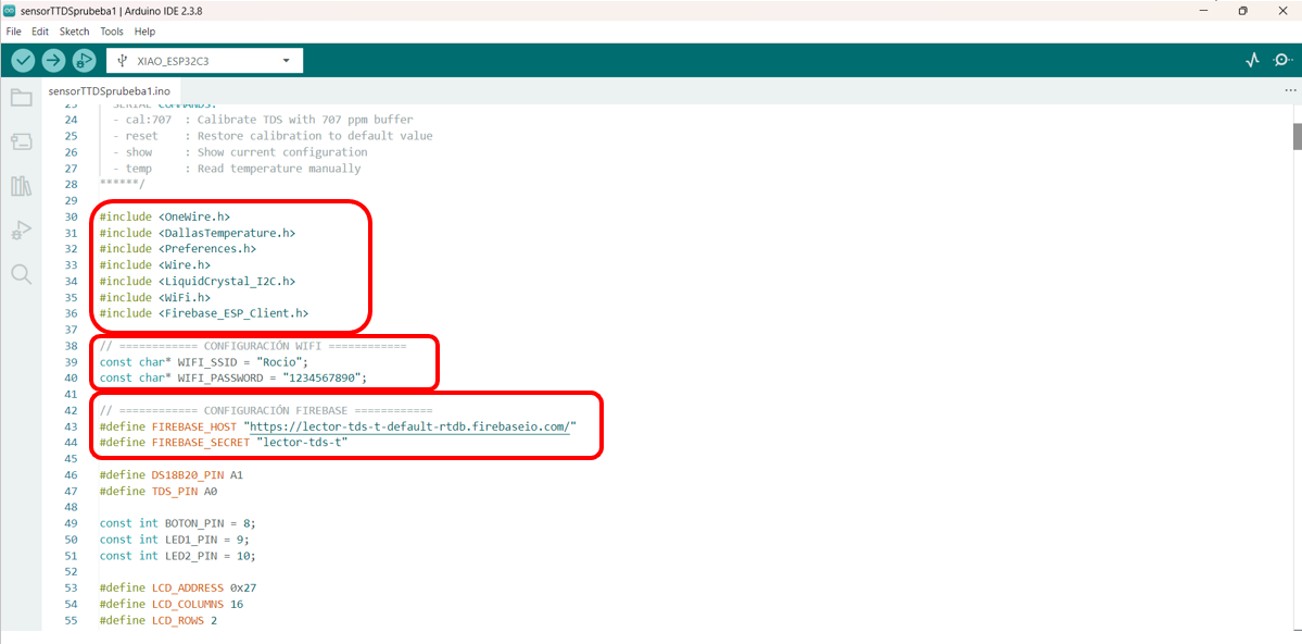
#include <OneWire.h>
#include <DallasTemperature.h>
#include <Preferences.h>
#include <Wire.h>
#include <LiquidCrystal_I2C.h>
#include <WiFi.h>
#include <Firebase_ESP_Client.h>
// WiFi and Firebase credentials were configured in the Arduino code.
// For public documentation, sensitive passwords should not be published.
#define DS18B20_PIN A1
#define TDS_PIN A0
const int BOTON_PIN = 8;
const int LED1_PIN = 9;
const int LED2_PIN = 10;
#define LCD_ADDRESS 0x27
#define LCD_COLUMNS 16
#define LCD_ROWS 2
// The complete sketch reads sensors, updates the LCD, sends data to Firebase,
// and checks Firebase commands to control the LEDs remotely.
Img. 30: The most important step was downloading the required libraries and configuring WiFi and Firebase.
This allows information to be stored and structured in the database.
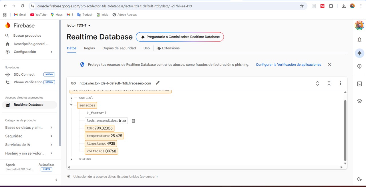
Img. 31: Data sent by the ESP32 in JSON format to Firebase.
4. Receiving data in the web application
A web application was designed in VS Code to visualize data in real time and interact with the device. The web application uses JavaScript to connect to Firebase, listen to real-time changes, and automatically update the interface. This is achieved using: database.ref('/sensores').on('value', ...).
Web application code
<!DOCTYPE html>
<html lang="en">
<head>
    <meta charset="UTF-8">
    <meta name="viewport" content="width=device-width, initial-scale=1.0, user-scalable=no">
    <title>TDS Monitor - Real Time Control</title>

    <!-- Firebase SDK -->
    <script src="https://www.gstatic.com/firebasejs/9.22.2/firebase-app-compat.js"></script>
    <script src="https://www.gstatic.com/firebasejs/9.22.2/firebase-database-compat.js"></script>

    <!-- The interface includes cards for TDS, temperature, sensor voltage,
         water quality, LED status, and real-time Firebase connection. -->
</head>
<body>
    <!-- Complete web dashboard designed in HTML, CSS and JavaScript -->
</body>
</html>
Img. 32: Graphical interface generated to visualize real-time data and interact with the device from any device with internet connection.
The data is displayed in a graphical interface that includes visualization cards (TDS, temperature, voltage), a water quality indicator, and system status. The interface is designed to be intuitive, responsive, and real time.
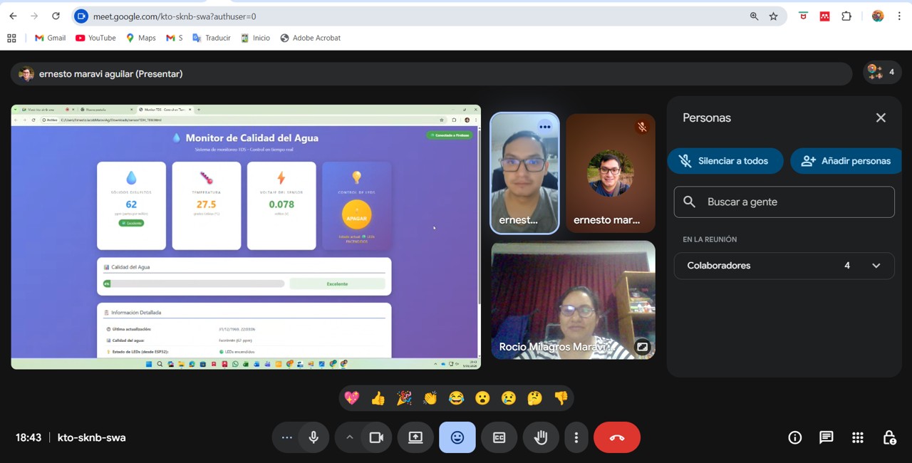
5. System control (user → hardware interaction)
The user can interact through a button that sends a command to Firebase. The ESP32 reads that command and activates or deactivates the LEDs.
The system implements bidirectional communication: input data from sensors → Firebase → web, and output commands from the user → Firebase → ESP32.
Img. 33: To test the system, I sent the folder generated in VS Code to my brother in Lima. Through a call, we interacted with my board: he could see my sensor values in real time and turn my LED on and off remotely.
Video 1: Remote interaction test using the Firebase web interface.
6. Advantages of the approach used
real-time communication
access from any device
no direct connection to the microcontroller is required
scalable for IoT projects
user-friendly interface
7. Problems encountered
During development, some issues occurred:
WiFi connection: Difficulty connecting to some networks. Solution: use of the mobile phone hotspot.
Firebase configuration: Errors due to security rules. Solution: temporarily enable read/write permissions.
GPIO pins: Error when using invalid pins. Solution: correct the ESP32 pin mapping.
8. Conclusion
The use of Firebase allowed me to effectively integrate the physical world with a digital interface, achieving an interactive real-time system.
This project demonstrates how an embedded board can communicate with a modern web application, allowing remote monitoring and system control from anywhere.
9. Personal reflection
This work allowed me to understand how communication between hardware and software works in IoT systems. At the beginning, Firebase configuration and connection with the ESP32 were complex, but once achieved, the system became very powerful and flexible.
Now I can visualize how these systems can be applied in real projects such as environmental monitoring, smart agriculture, or automated control.
Files & Downloads
This section includes the main files used during the Interface and Application Programming week, including the Arduino IDE code for the ESP32 and the Firebase web application files.