Assignment requirements
Group assignment
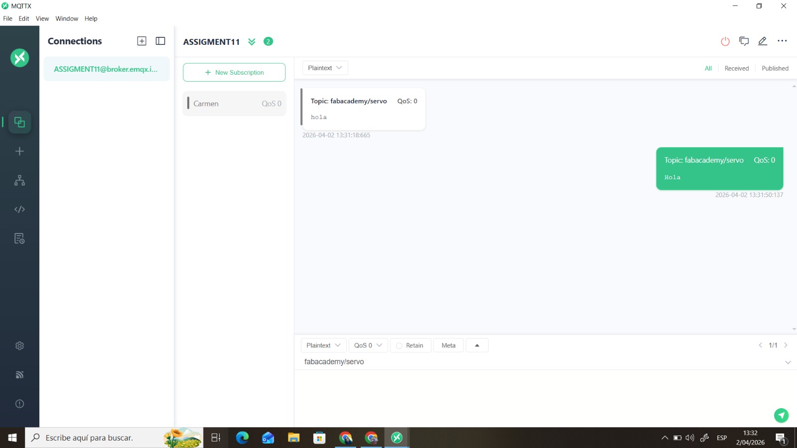
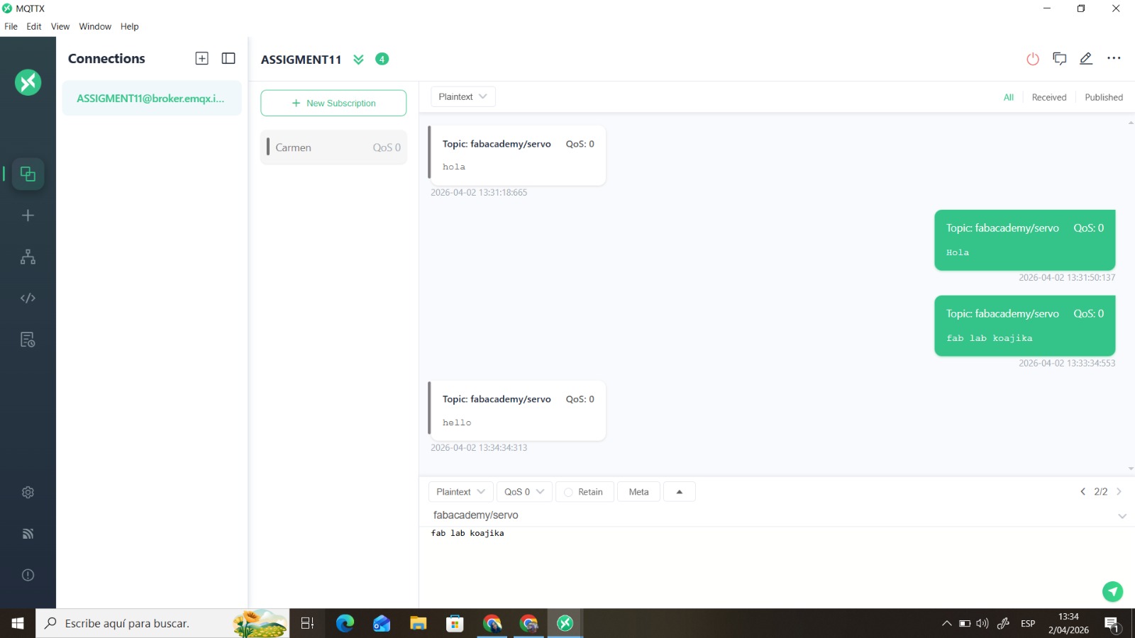
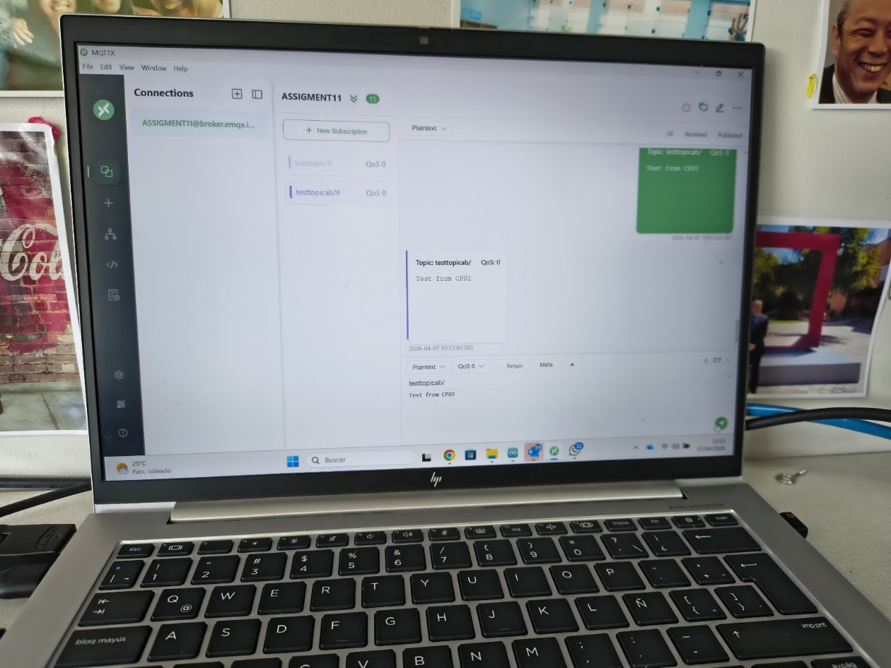
- Send a message between two projects
- Document your work to the group work page and reflect on your individual page what you learned
Individual assignment
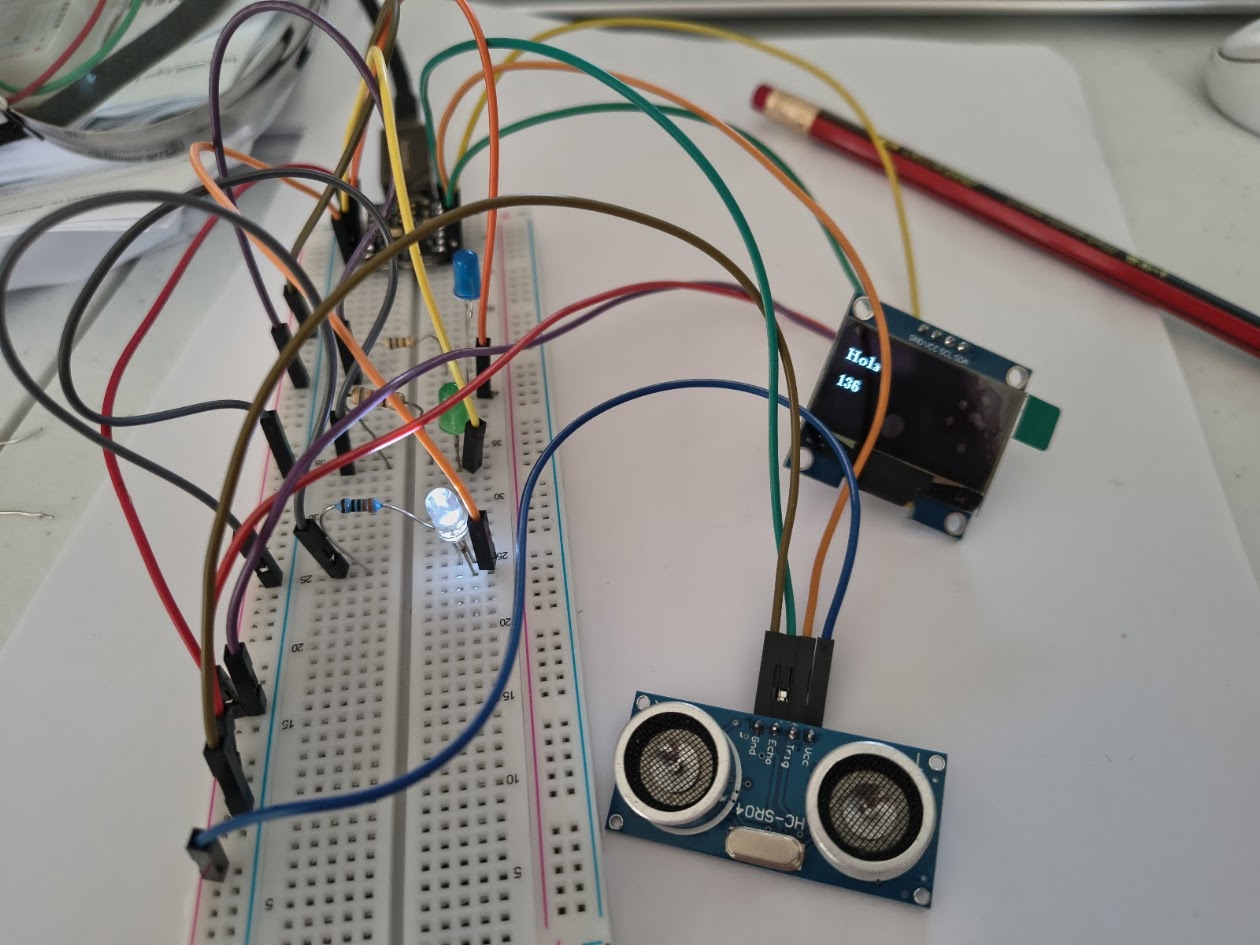
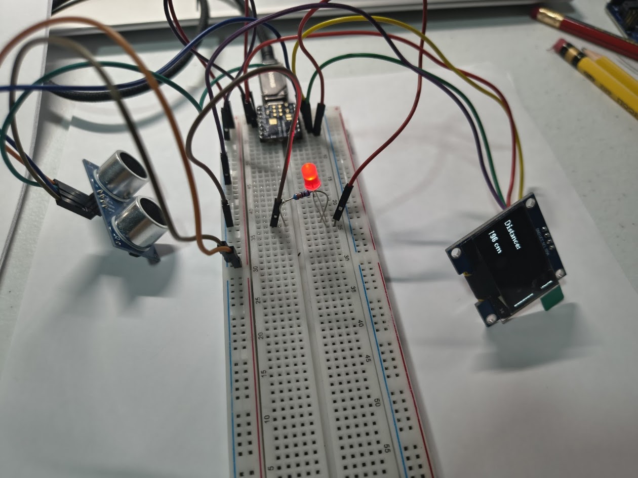
- Design, build and connect wired or wireless node(s) with network or bus addresses and a local input and/or output device(s)
Progress status
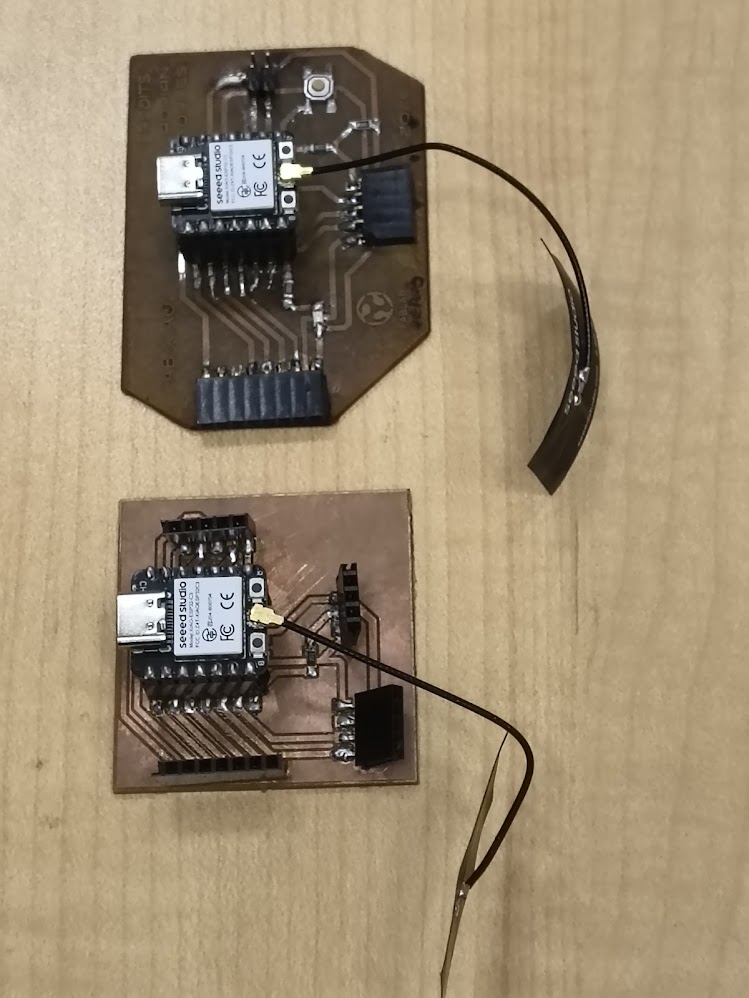
Send a message between two projects
Design, build and connect wired or wireless node(
Upload source files
1) Introduction
Closing gaps
- Learn about commnunication with two devices
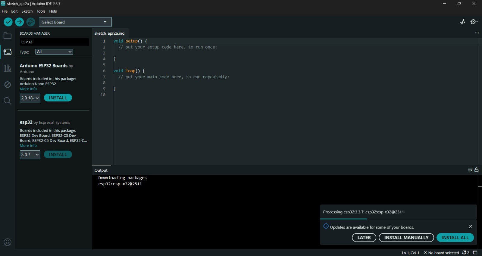
- Interact more about communication protocols and more about Arduino IDE
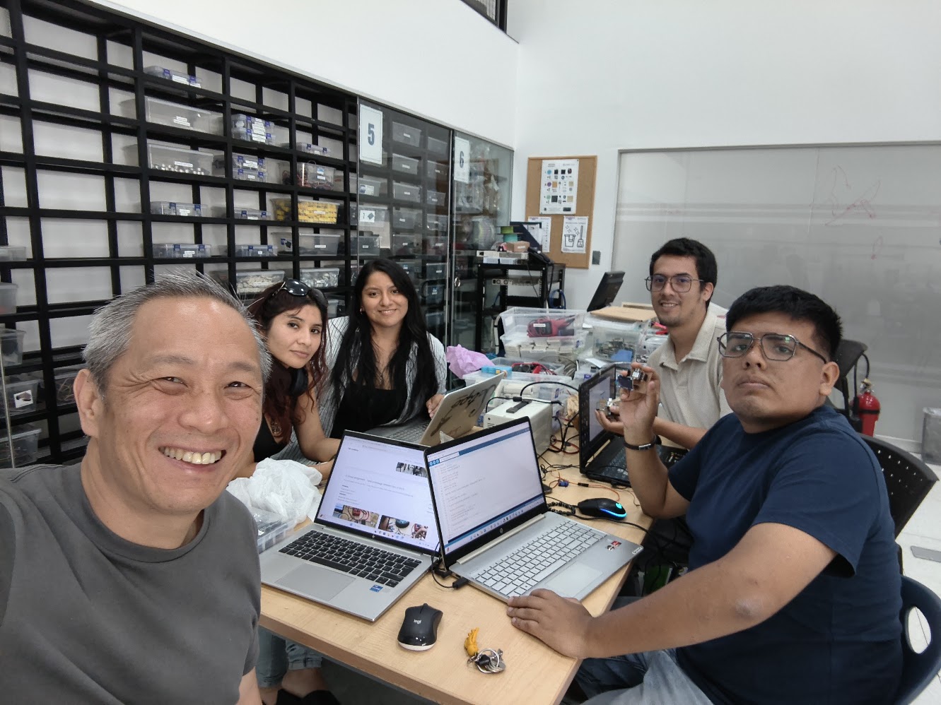
- Discuss the group project
- Develop the individual project
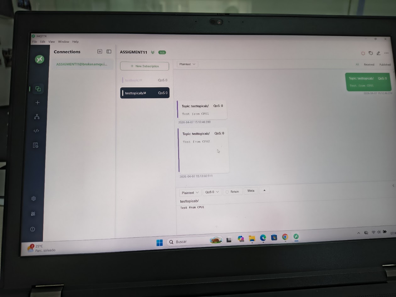
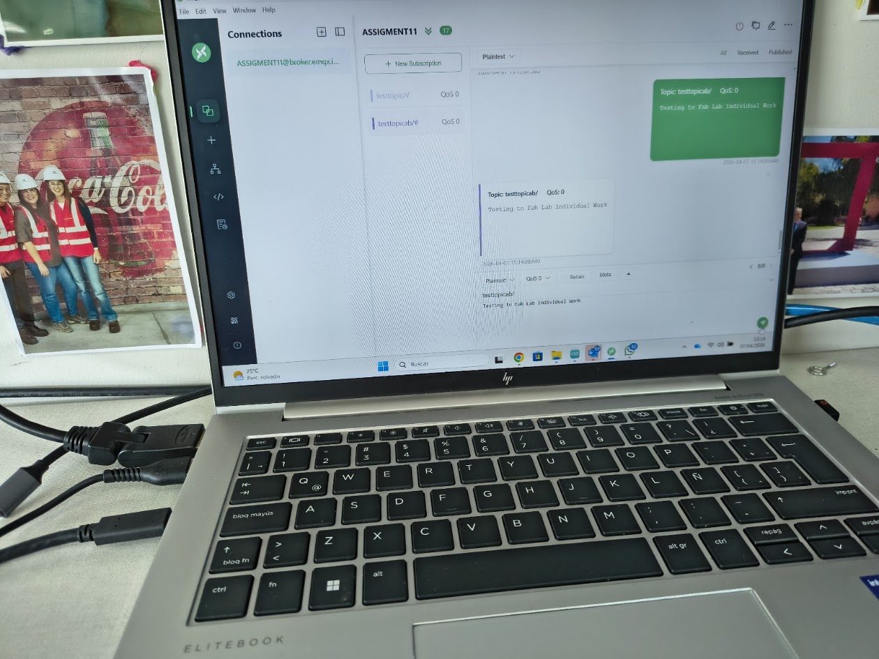
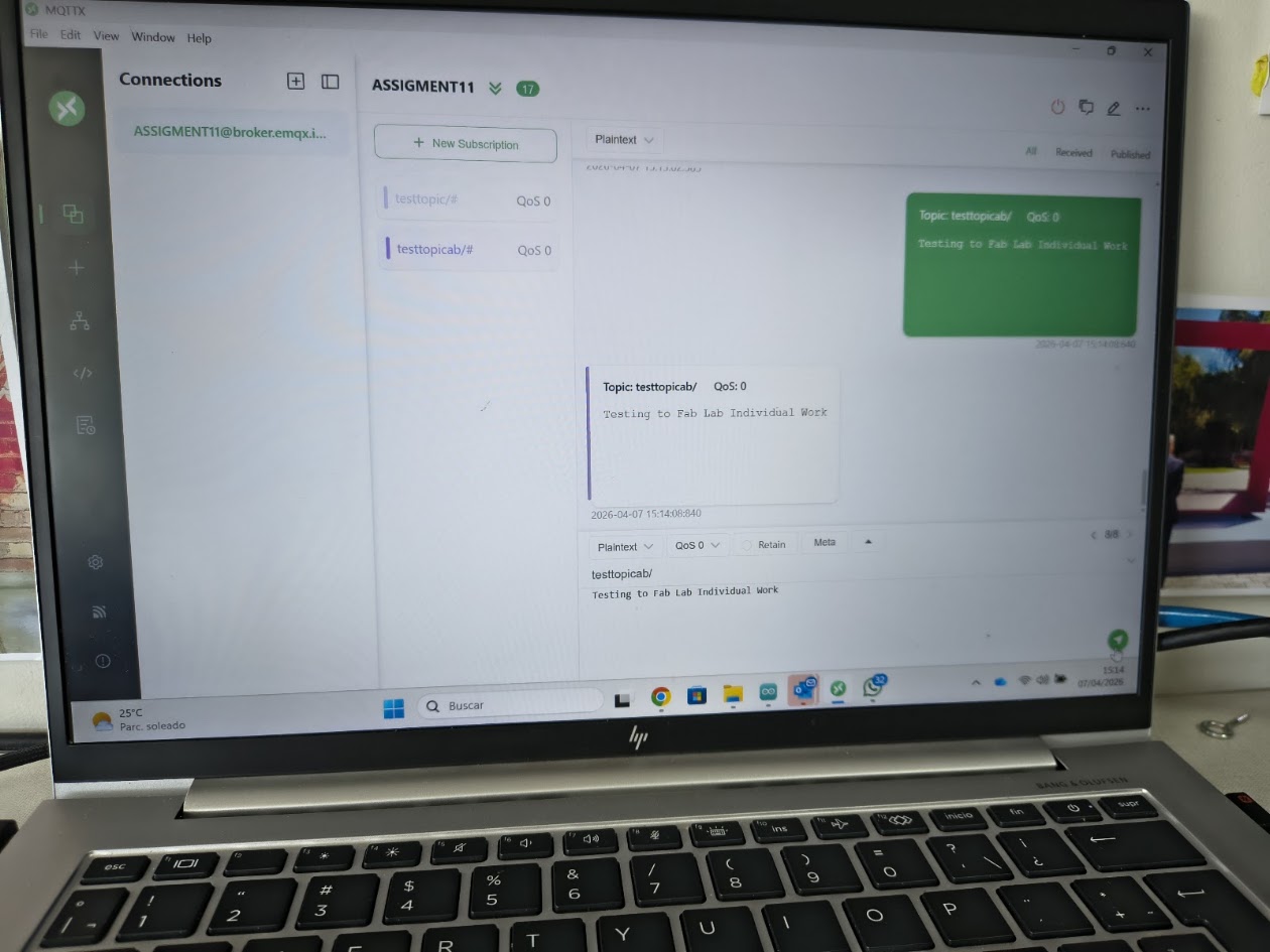
2) Group assignment - Send a message between two projects
For more details visit Fab Lab Peru Week 11 Group assignment
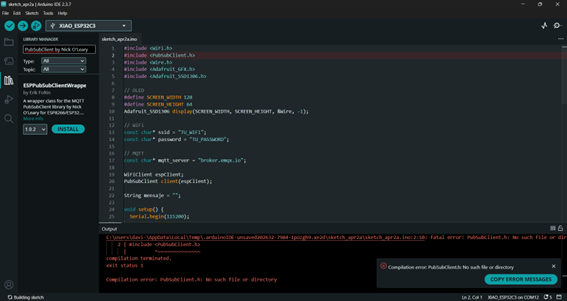
Problems
Projects don't connect
Review connections
Solutions
Review the cable connections
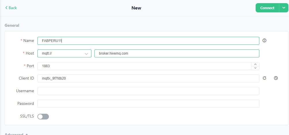
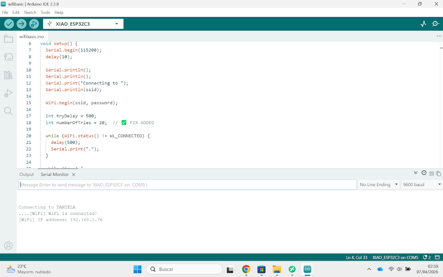
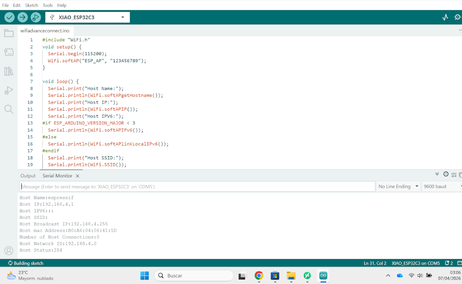
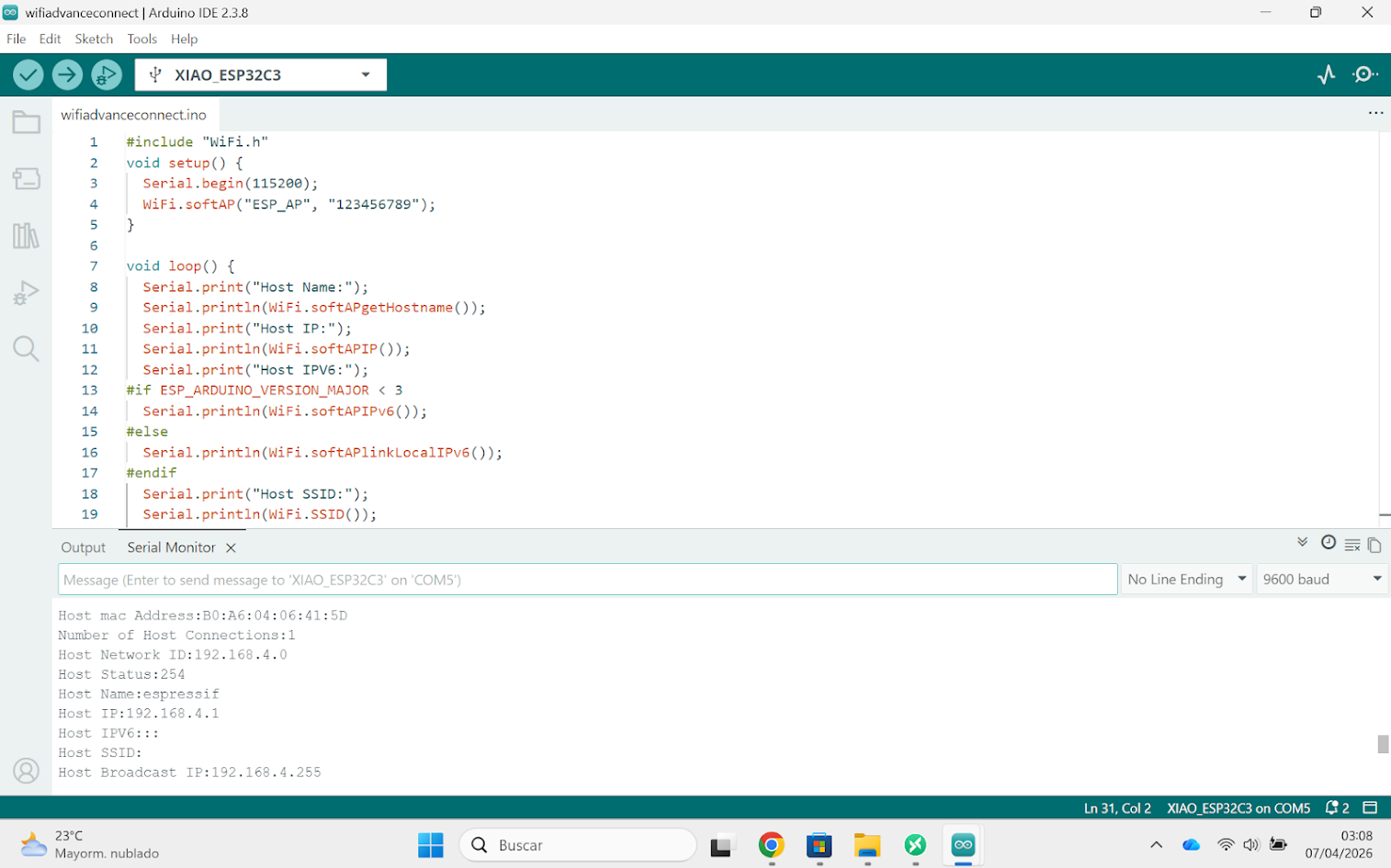
Review the software configuration

              // Programming Project 1 - Counter with OLED display - Client
              // TU_WIFI

                  #include               //Library for WiFi connection
                  #include        //Library for MQTT client communication
                  #include                //Library for I2C communication
                  #include        //Library for graphics on OLED
                  #include    //Library for OLED display

                  #define SCREEN_WIDTH 128        // OLED display width, in pixels
                  #define SCREEN_HEIGHT 64        // OLED display height, in pixels

                  Adafruit_SSD1306 display(SCREEN_WIDTH, SCREEN_HEIGHT, &Wire, -1);   // Create an instance of the OLED display

                  // WiFi
                  const char* ssid = "IoT_UP";                  //WiFi network name
                  const char* password = "ti6WzfPsk3WnqZpt8d";  //WiFi network password

                  // MQTT
                  const char* mqtt_server = "broker.emqx.io";   //MQTT broker address

                  WiFiClient espClient;                         // Create a WiFi client object
                  PubSubClient client(espClient);               // Create an MQTT client object using the WiFi client

                  String mensaje = "";             // Variable to store the received message
                  bool nuevoMensaje = false;       // Flag to indicate if a new message has been received

                  void setup() {
                    Serial.begin(115200);         // Start serial communication for debugging

                    // OLED
                    Wire.begin(D4, D5);                         // Initialize I2C communication with specified SDA and SCL pins
                    display.begin(SSD1306_SWITCHCAPVCC, 0x3C);  // Initialize the OLED display with the I2C address 0x3C

                    display.clearDisplay();                    // Clear the display buffer
                    display.setTextSize(2);                    // Set text size to 2 (double the normal size)
                    display.setTextColor(SSD1306_WHITE);       // Set text color to white
                    display.setCursor(0, 20);                  // Set the cursor position to (0, 20) for text display
                    display.println("Contador");               // Print "Contador" on the OLED display
                    display.display();                         // Update the OLED display with the contents of the display buffer

                    // WiFi
                    WiFi.begin(ssid, password);               // Connect to the WiFi network using the specified SSID and password
                    while (WiFi.status() != WL_CONNECTED) {
                      delay(500);                             // Wait until the WiFi connection is established
                    }

                    // MQTT
                    client.setServer(mqtt_server, 1883);      // Set the MQTT broker address and port for the client
                    client.setCallback(callback);            // Set the callback function to handle incoming MQTT messages
                  }

                  void reconnect() {
                    while (!client.connected()) {           //  Keep trying to connect until the MQTT client is connected
                      if (client.connect("XIAO_OLED")) {    // Attempt to connect to the MQTT broker with the client ID "XIAO_OLED"
                        client.subscribe("fabacademy/contador");// Subscribe to the MQTT topic "fabacademy/contador" to receive messages published to that topic
                      } else {
                        delay(2000);                        // Wait before retrying to connect if the connection attempt fails
                      }
                    }
                  }

                  void callback(char* topic, byte* payload, unsigned int length) {
                    mensaje = "";                           // Clear the message variable before processing the new message

                    for (int i = 0; i < length; i++) {      // Iterate through the payload bytes and append them to the message string
                      mensaje += (char)payload[i];         // Convert each byte in the payload to a character and append it to the message string
                    }

                    Serial.println(mensaje);              // Print the received message to the serial monitor for debugging
                    nuevoMensaje = true;                  // Set the flag to indicate that a new message has been received and is ready to be displayed on the OLED
                  }

                  void loop() {
                    if (!client.connected()) {
                      reconnect();                        //  If the MQTT client is not connected, call the reconnect function to establish a connection to the MQTT broker
                    }
                    client.loop();

                    if (nuevoMensaje) {                   // If a new message has been received, update the OLED display with the new message
                      display.clearDisplay();
                      display.setTextSize(3);
                      display.setTextColor(SSD1306_WHITE);
                      display.setCursor(20, 20);
                      display.println(mensaje);           // Print the received message on the OLED display
                      display.display();

                      nuevoMensaje = false;
                    }
                  }
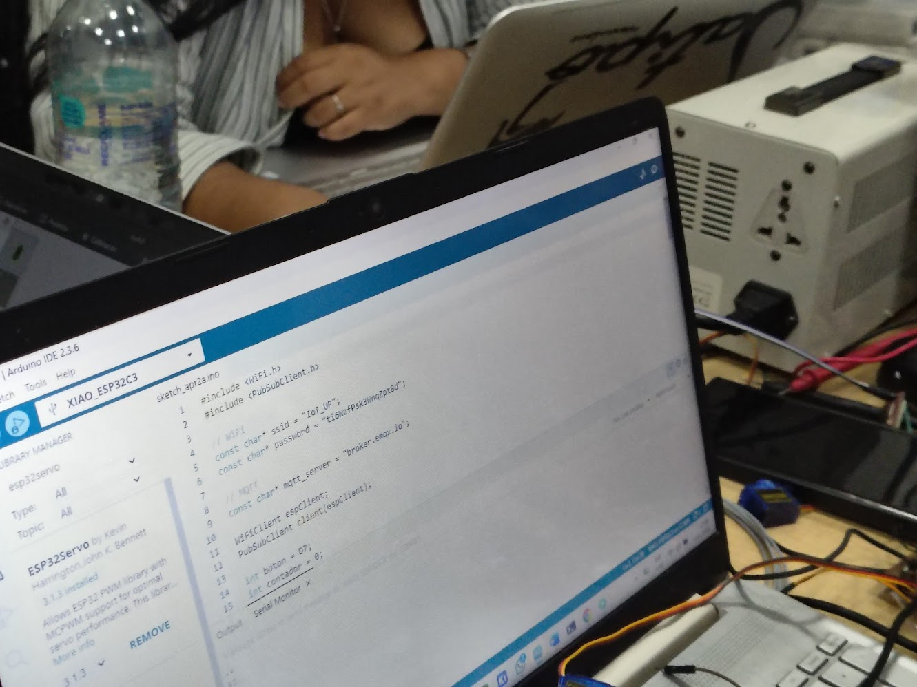
// Programming Project 2 - Button counter with MQTT - Server
                       // TU_WIFI

                #include                              //Library for WiFi connection
                #include                      //Library for MQTT client communication

                // WiFi
                const char* ssid = "IoT_UP";                  //WiFi network name
                const char* password = "ti6WzfPsk3WnqZpt8d";  //WiFi network password

                // MQTT
                const char* mqtt_server = "broker.emqx.io";   //MQTT broker address

                WiFiClient espClient;                         // Create a WiFi client object
                PubSubClient client(espClient);               //  Create an MQTT client object using the WiFi client

                int boton = D7;                               // Define the pin for the button (change to the GPIO/pin you are using)
                int contador = 0;                             // Variable to store the count of button presses
                bool estadoAnterior = HIGH;                   // Variable to store the previous state of the button (initialized to HIGH assuming the button is not pressed)

                void setup() {
                  Serial.begin(115200);                       // Start serial communication for debugging
                  pinMode(boton, INPUT_PULLUP);              // Set the button pin as an input with an internal pull-up resistor (assuming the button is active LOW)

                  WiFi.begin(ssid, password);               // Connect to the WiFi network using the specified SSID and password
                  while (WiFi.status() != WL_CONNECTED) {   //  Wait until the WiFi connection is established
                    delay(500);
                  }

                  client.setServer(mqtt_server, 1883);      // Set the MQTT broker address and port for the client
                }

                void reconnect() {
                  while (!client.connected()) {           // Keep trying to connect until the MQTT client is connected
                    client.connect("XIAO_BOTON");         // Attempt to connect to the MQTT broker with the client ID "XIAO_BOTON"
                  }
                }

                void loop() {
                  if (!client.connected()) reconnect();   // If the MQTT client is not connected, call the reconnect function to establish a connection to the MQTT broker
                  client.loop();

                  bool estadoActual = digitalRead(boton); // Read the current state of the button (HIGH or LOW)

                  // Detecta pulsación
                  if (estadoAnterior == HIGH && estadoActual == LOW) {
                    contador++;                          // Increment the counter when a button press is detected (transition from HIGH to LOW)

                    String msg = String(contador);      // Convert the counter value to a string to be published as an MQTT message
                    Serial.println(msg);                // Print the current count to the serial monitor for debugging

                    client.publish("fabacademy/contador", msg.c_str()); // Publish the current count to the MQTT topic "fabacademy/contador" as a string message

                    delay(300);                         // Add a small delay to debounce the button and prevent multiple counts from a single press
                  }

                  estadoAnterior = estadoActual;      // Update the previous state of the button to the current state for the next iteration of the loop

                }
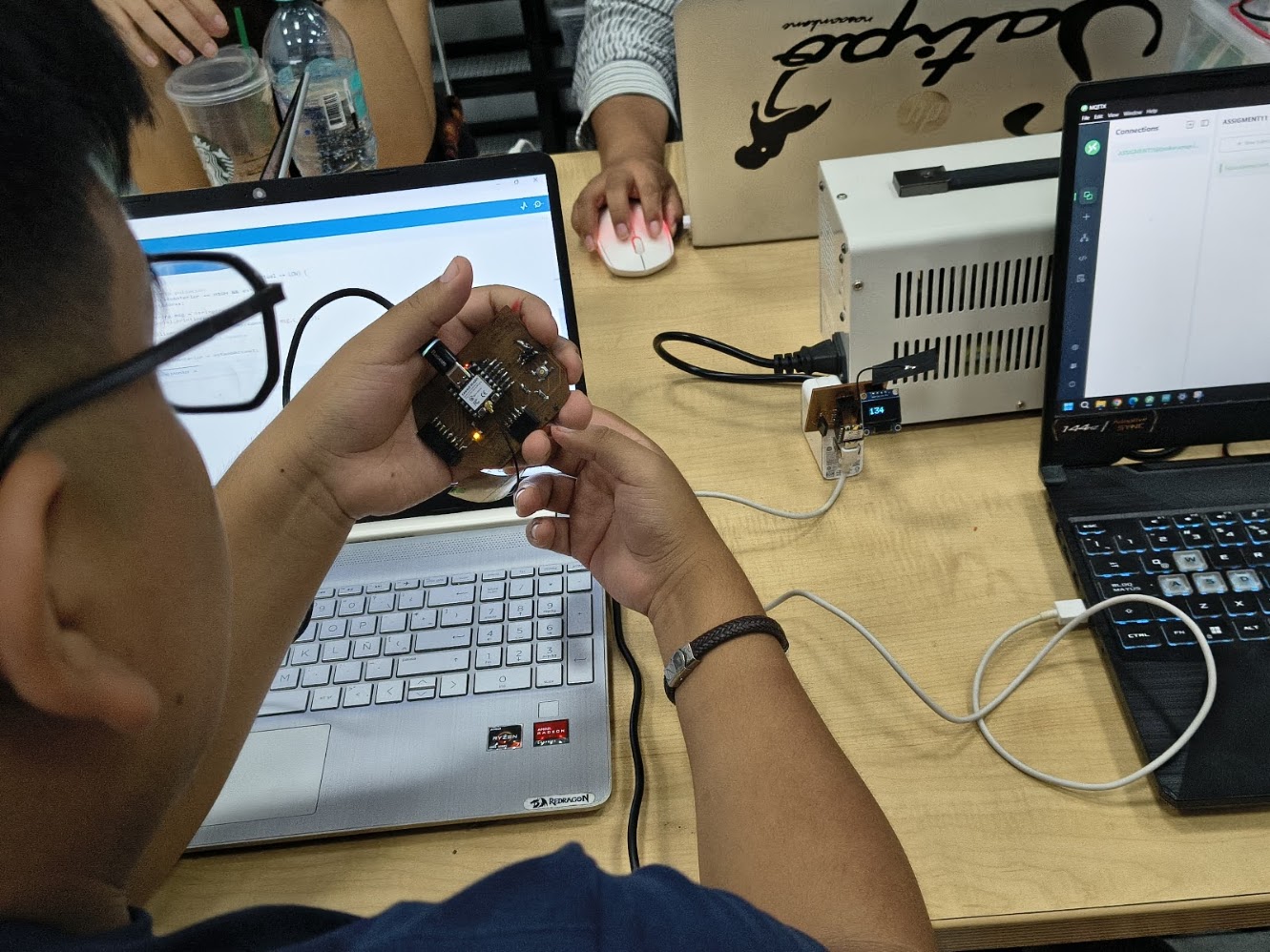
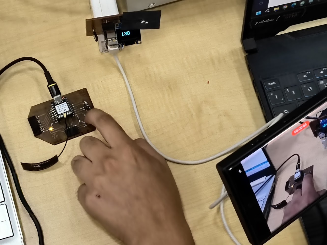
Video demonstration
4) Individual assigment
Problems
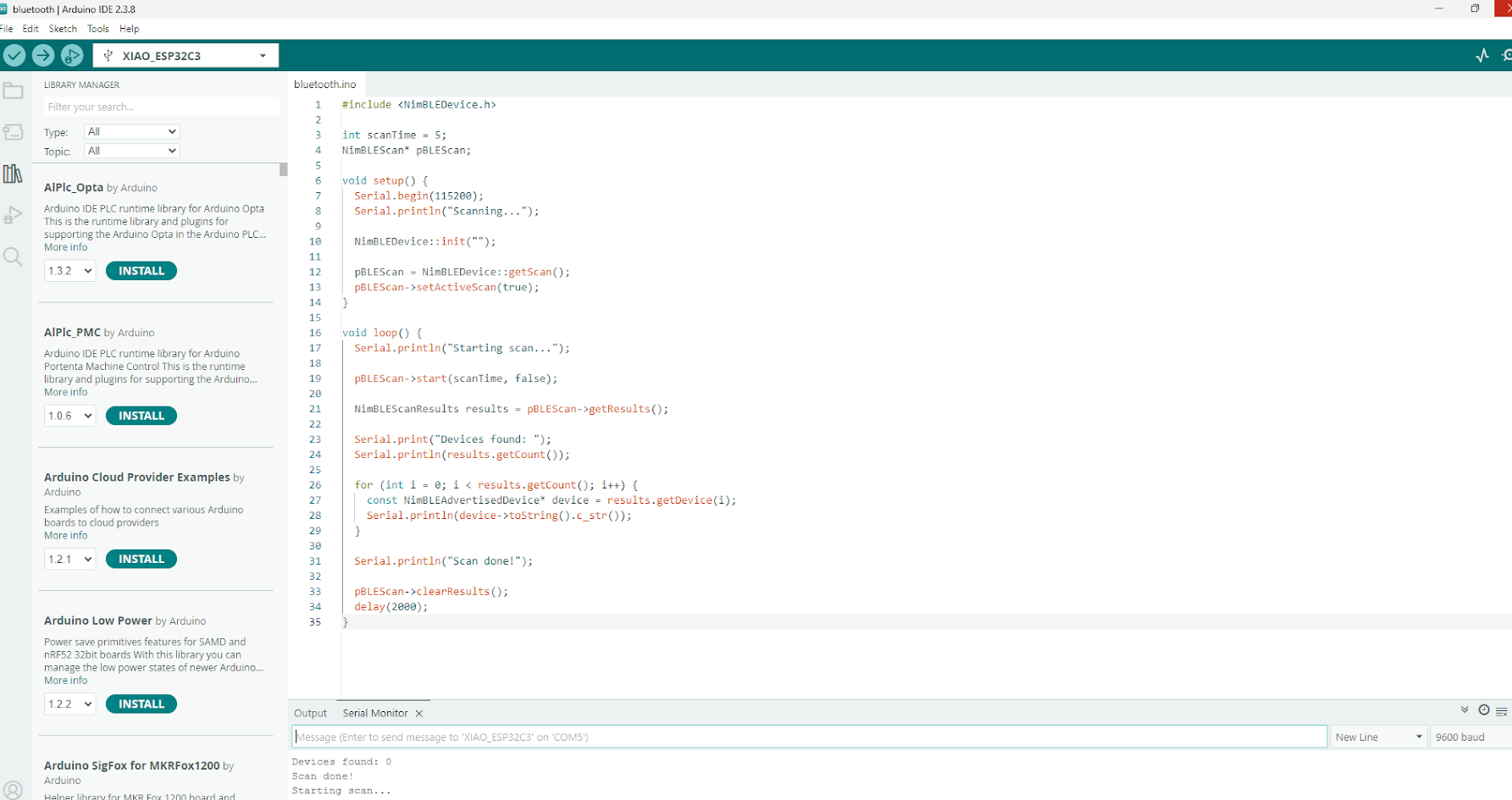
Define libraries, NimBLE or BLE libraries not found
Compiling errors, considering the library design
Programming skills required
Solutions
Advance step by step
Support with library documentation
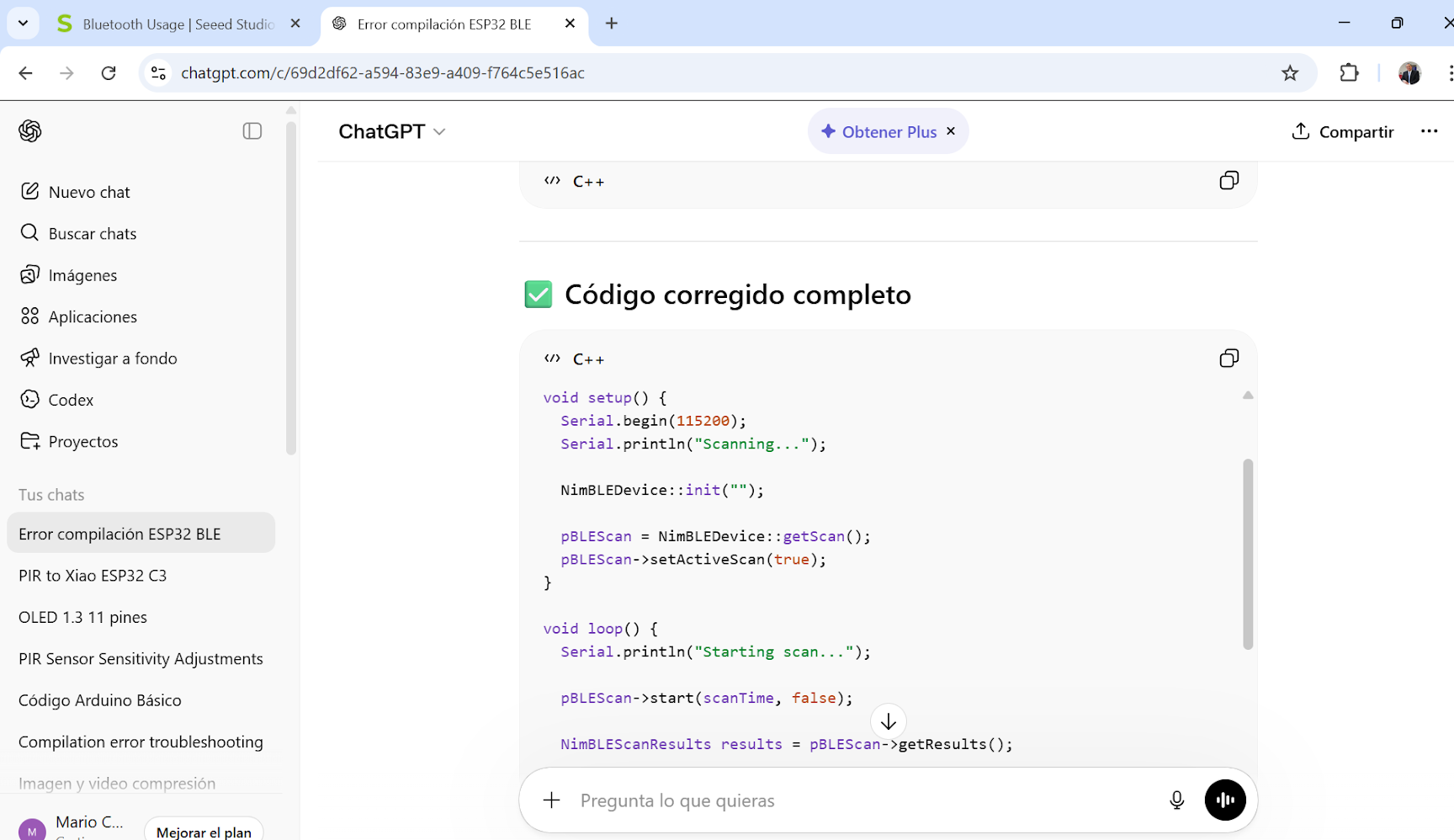
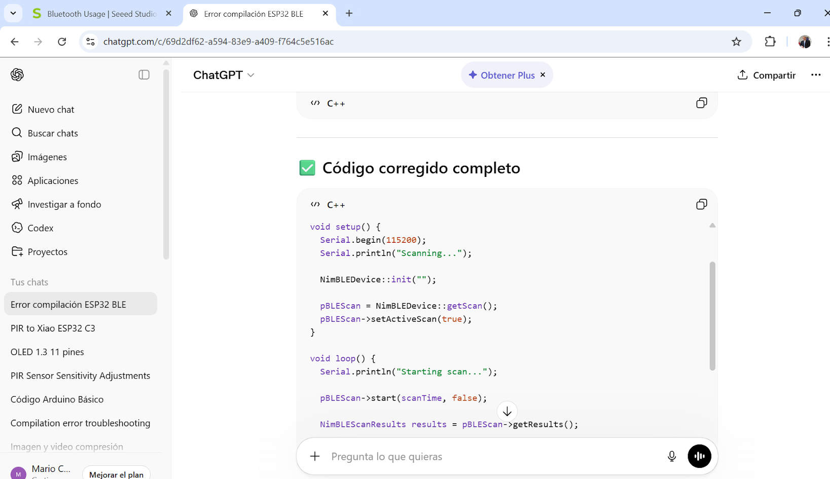
Support with online resources - ChatGPT
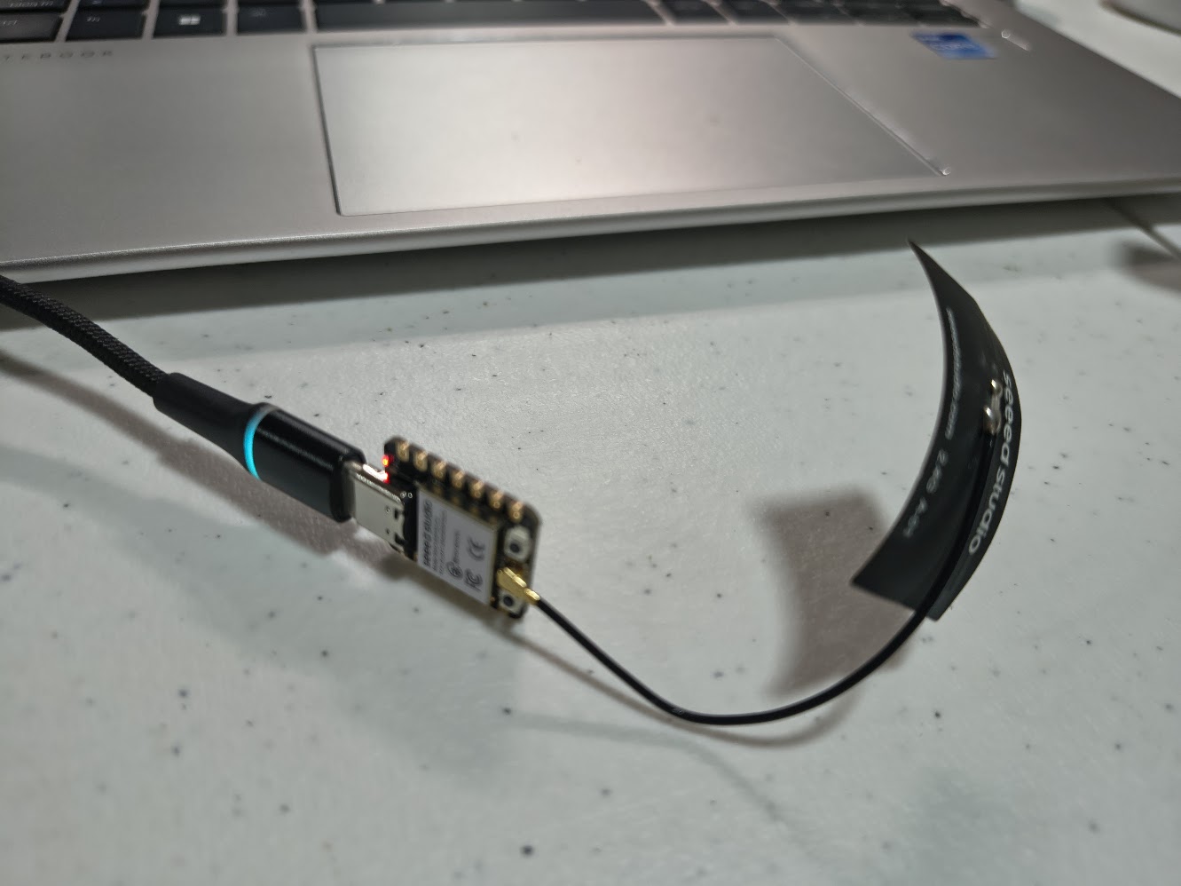
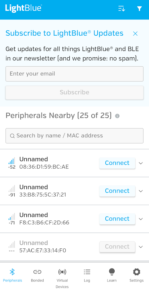
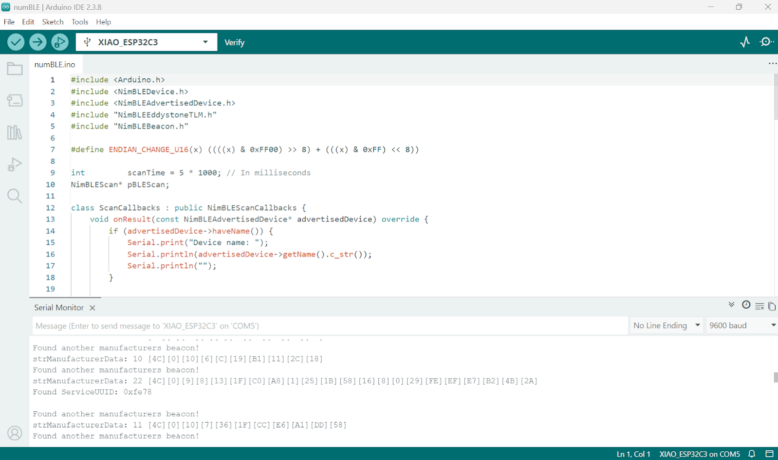
// Scanning Bluetooth devices
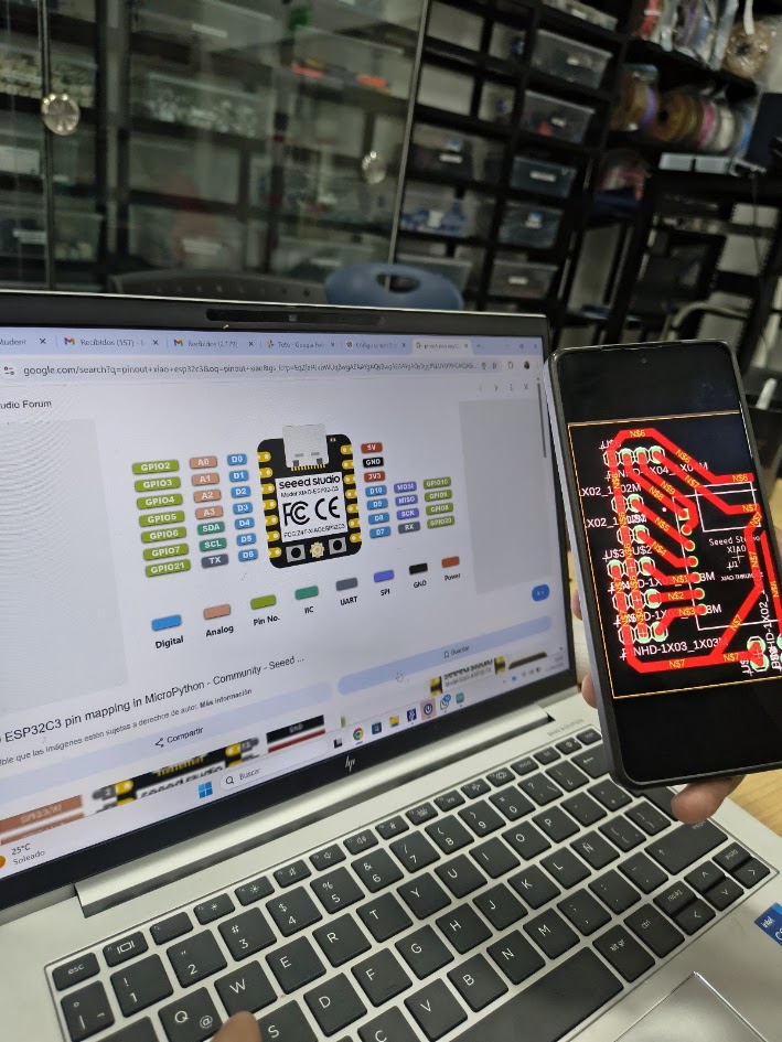
// Board: Seeed Studio XIAO ESP 32 C3
#include
int scanTime = 5;
NimBLEScan* pBLEScan;
void setup() {
Serial.begin(115200);
Serial.println("Scanning...");
NimBLEDevice::init("");
pBLEScan = NimBLEDevice::getScan();
pBLEScan->setActiveScan(true);
}
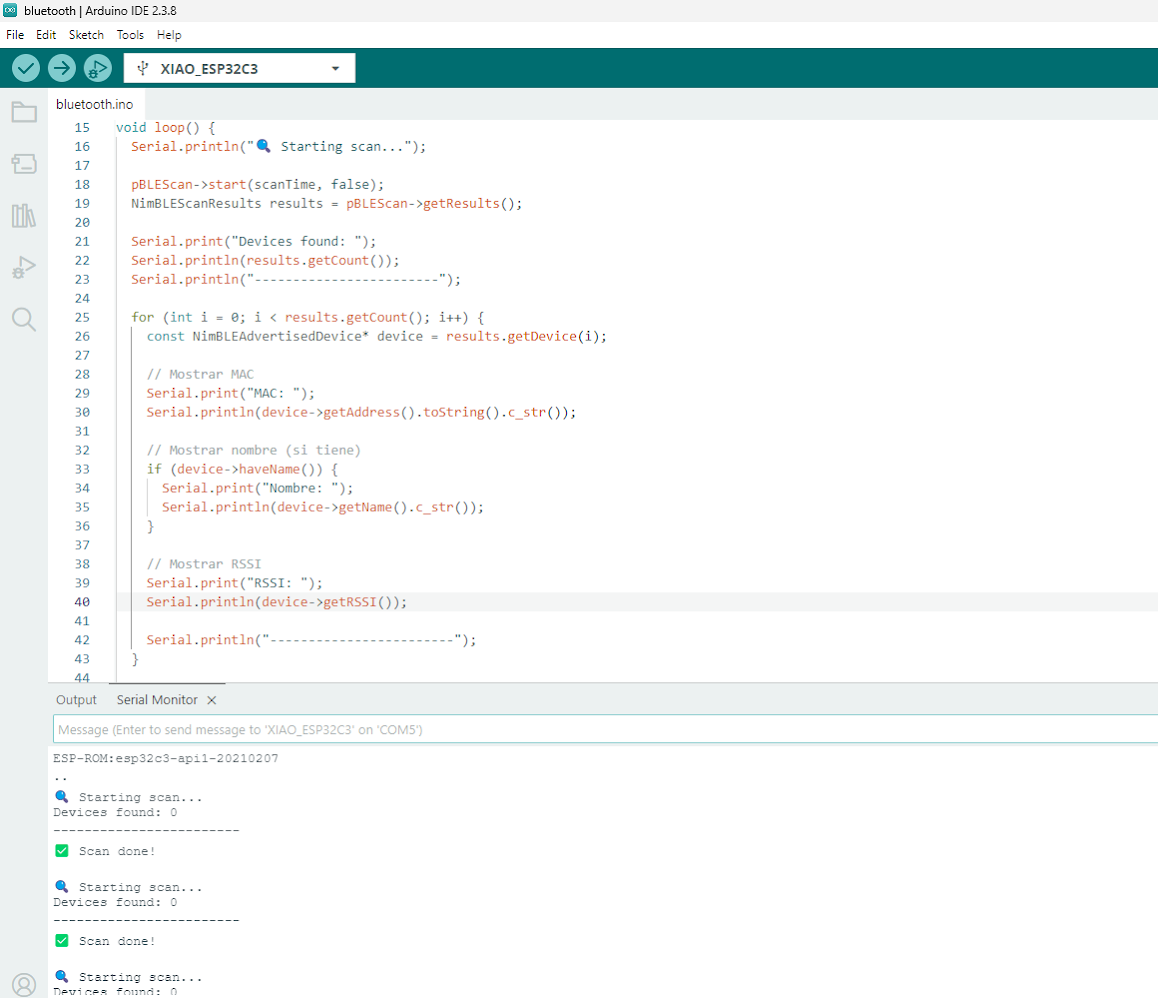
void loop() {
Serial.println("🔍 Starting scan...");
pBLEScan->start(scanTime, false);
NimBLEScanResults results = pBLEScan->getResults();
Serial.print("Devices found: ");
Serial.println(results.getCount());
Serial.println("------------------------");
for (int i = 0; i < results.getCount(); i++) {
const NimBLEAdvertisedDevice* device = results.getDevice(i);
// Mostrar MAC
Serial.print("MAC: ");
Serial.println(device->getAddress().toString().c_str());
// Mostrar nombre (si tiene)
if (device->haveName()) {
Serial.print("Nombre: ");
Serial.println(device->getName().c_str());
}
// Mostrar RSSI
Serial.print("RSSI: ");
Serial.println(device->getRSSI());
Serial.println("------------------------");
}
Serial.println("✅ Scan done!\n");
pBLEScan->clearResults();
delay(2000);
}
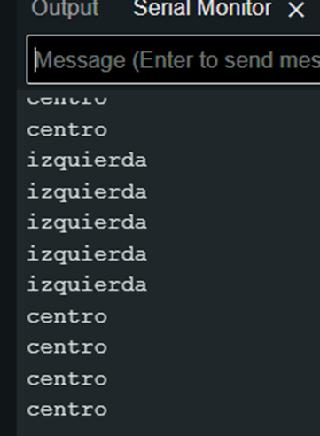
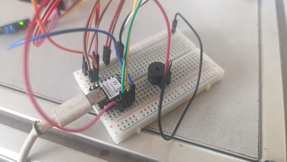
// Using three TCRT5000L reflective optical sensor & buzzer - Center or not
              // Input devices
              // Board: Seeed Studio XIAO ESP 32 C3

              #define sensor1 D6   // cambia al GPIO/pin que uses
              #define sensor2 D5   // cambia al GPIO/pin que uses
              #define sensor3 D4   // cambia al GPIO/pin que uses


              void setup() {
                  Serial.begin(115200);
                  pinMode(sensor1, INPUT);
                  pinMode(sensor2, INPUT);
                  pinMode(sensor3, INPUT);
                  pinMode(D3, OUTPUT);
              }

              void loop() {
                int val1 = digitalRead(sensor1);
                int val2 = digitalRead(sensor2);
                int val3 = digitalRead(sensor3);
                if(val1==1){
                  Serial.println("izquierda");
                    digitalWrite (D3, HIGH);
                    delayMicroseconds (5000);
                    digitalWrite (D3, LOW);
                    delayMicroseconds (100000);
                }
                else if(val2==1){
                  Serial.println("centro");
                }
                else if(val3==1){
                  Serial.println("derecha");
                    digitalWrite (D3, HIGH);
                    delayMicroseconds (5000);
                    digitalWrite (D3, LOW);
                    delayMicroseconds (100000);
                }
                else{
                  Serial.println("error");
                    digitalWrite (D3, HIGH);
                    delayMicroseconds (5000);
                    digitalWrite (D3, LOW);
                    delayMicroseconds (100000);
                }
                delay(100);
              }
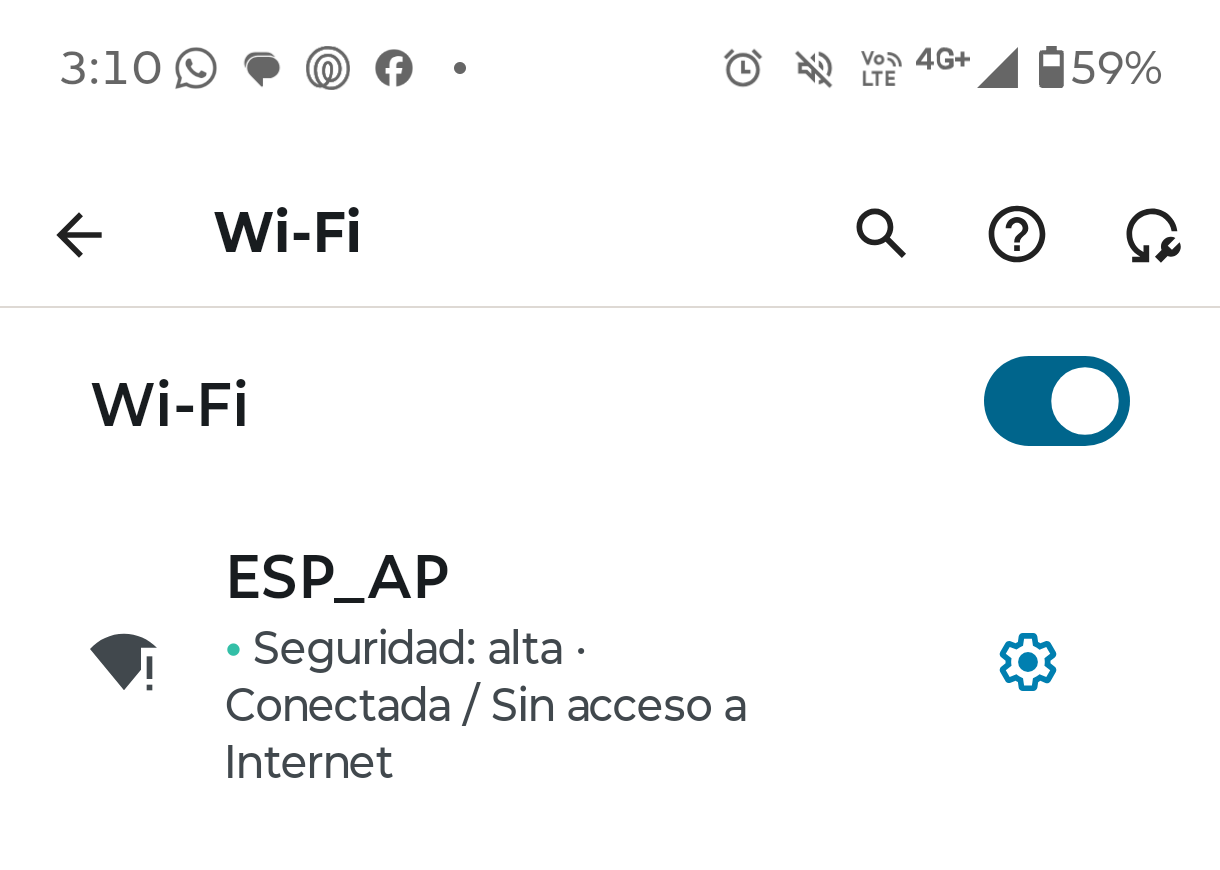

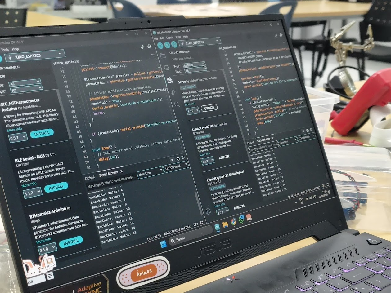
 // Client at Arduino IDE
              // Client & Server Connection by blue tooth
              // Board: Seeed Studio XIAO ESP 32 C3

                        #include
                        #include
                        #include

                        #define SERVICE_UUID        "12345678-1234-1234-1234-123456789abc"
                        #define CHARACTERISTIC_UUID "abcd1234-ab12-ab12-ab12-abcdef123456"

                        BLEClient* pClient;
                        BLERemoteCharacteristic* pRemoteChar;
                        bool conectado = false;

                        // Callback que se ejecuta al recibir un dato
                        void notifyCallback(BLERemoteCharacteristic* pChar, uint8_t* pData, size_t length, bool isNotify) {
                          String dato = "";
                          for (int i = 0; i < length; i++) dato += (char)pData[i];
                          Serial.println("Recibido: " + dato);
                        }

                        void setup() {
                          Serial.begin(115200);
                          BLEDevice::init("ESP32-Cliente");

                          BLEScan* pScan = BLEDevice::getScan();
                          BLEScanResults* results = pScan->start(5, false);  // escanea 5 segundos

                          for (int i = 0; i < results->getCount(); i++) {
                            BLEAdvertisedDevice device = results->getDevice(i);
                            if (device.getName() == "ESP32-Servidor") {
                              Serial.println("Servidor encontrado, conectando...");

                              pClient = BLEDevice::createClient();
                              pClient->connect(&device);

                              BLERemoteService* pService = pClient->getService(SERVICE_UUID);
                              pRemoteChar = pService->getCharacteristic(CHARACTERISTIC_UUID);

                              // Activar notificaciones automáticas
                              pRemoteChar->registerForNotify(notifyCallback);
                              conectado = true;
                              Serial.println("Conectado y escuchando.");
                              break;
                            }
                          }

                          if (!conectado) Serial.println("Servidor no encontrado.");
                        }

                        void loop() {
                          // Todo ocurre en el callback, no hace falta hacer nada aquí
                          delay(100);
                        }
 // Server at Arduino IDE
              // Client & Server Connection by blue tooth
              // Board: Seeed Studio XIAO ESP 32 C3

                        #include
                        #include
                        #include
                        #include

                        // UUIDs — puedes generarlos en https://www.uuidgenerator.net/
                        #define SERVICE_UUID        "12345678-1234-1234-1234-123456789abc"
                        #define CHARACTERISTIC_UUID "abcd1234-ab12-ab12-ab12-abcdef123456"

                        BLECharacteristic *pCharacteristic;
                        bool deviceConnected = false;
                        int contador = 0;

                        class MyServerCallbacks : public BLEServerCallbacks {
                          void onConnect(BLEServer* pServer)    { deviceConnected = true; }
                          void onDisconnect(BLEServer* pServer) { deviceConnected = false; pServer->startAdvertising(); }
                        };

                        void setup() {
                          Serial.begin(115200);
                          BLEDevice::init("ESP32-Servidor");

                          BLEServer *pServer = BLEDevice::createServer();
                          pServer->setCallbacks(new MyServerCallbacks());

                          BLEService *pService = pServer->createService(SERVICE_UUID);

                          pCharacteristic = pService->createCharacteristic(
                            CHARACTERISTIC_UUID,
                            BLECharacteristic::PROPERTY_READ | BLECharacteristic::PROPERTY_NOTIFY
                          );
                          pCharacteristic->addDescriptor(new BLE2902());

                          pService->start();
                          BLEDevice::startAdvertising();
                          Serial.println("Servidor BLE listo, esperando cliente...");
                        }

                        void loop() {
                          if (deviceConnected) {
                            String mensaje = "Valor: " + String(contador++);
                            pCharacteristic->setValue(mensaje.c_str());
                            pCharacteristic->notify();  // envía automáticamente al cliente
                            Serial.println("Enviado: " + mensaje);
                            delay(1000);
                          }
                      }
Video demonstration
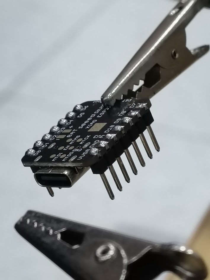
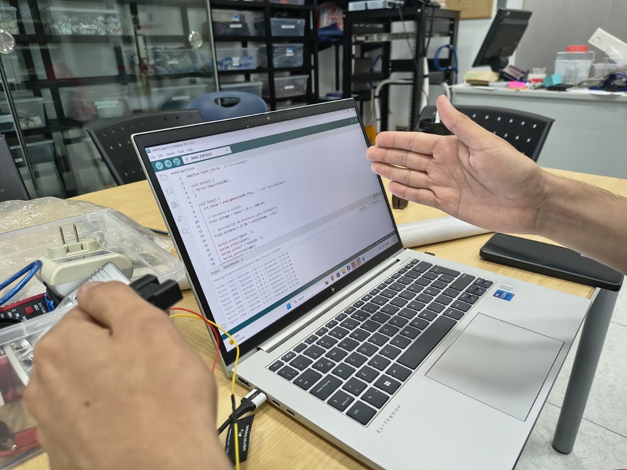
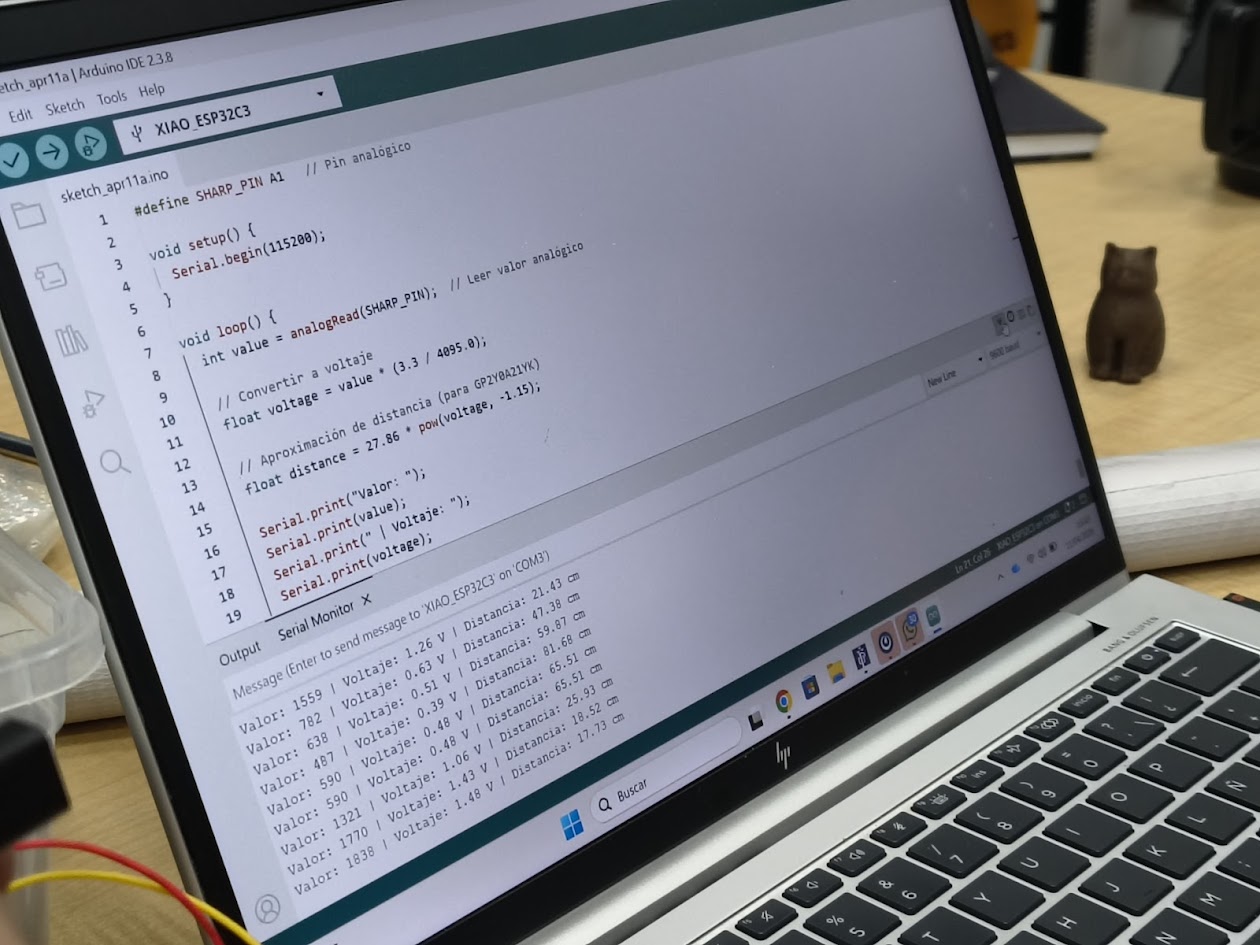
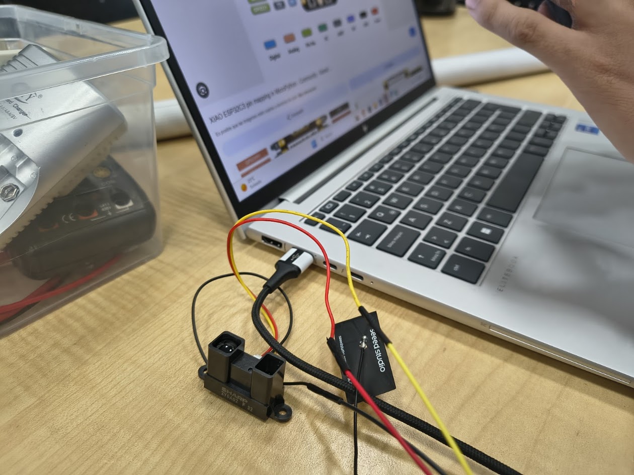
5) Final project advances
Devices
GP2Y0A21YK0F Sharp, infrared distance sensor, 10-80 cm
GP2Y0A02YK0F Sharp, infrared distance sensor, 20-150 cm
2Y0A710K Sharp, infrared distance sensor, 100 a 550cm
Reviewing the 50 mts pool


6) Final results
- Linked to the group assignment page
- Documented how you determined power consumption of an output device with your group
- Documented what you learned from interfacing output device(s) to microcontroller and controlling
- Linked to the board you made in a previous assigment or documented your design and fabrication
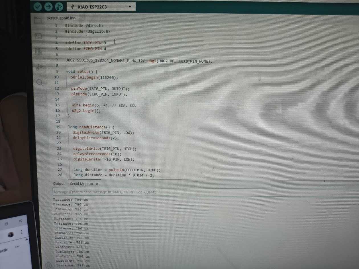
- Explain how your code works
- Explained any problems you encountered and how you fixed them
- Include original source code and any design files
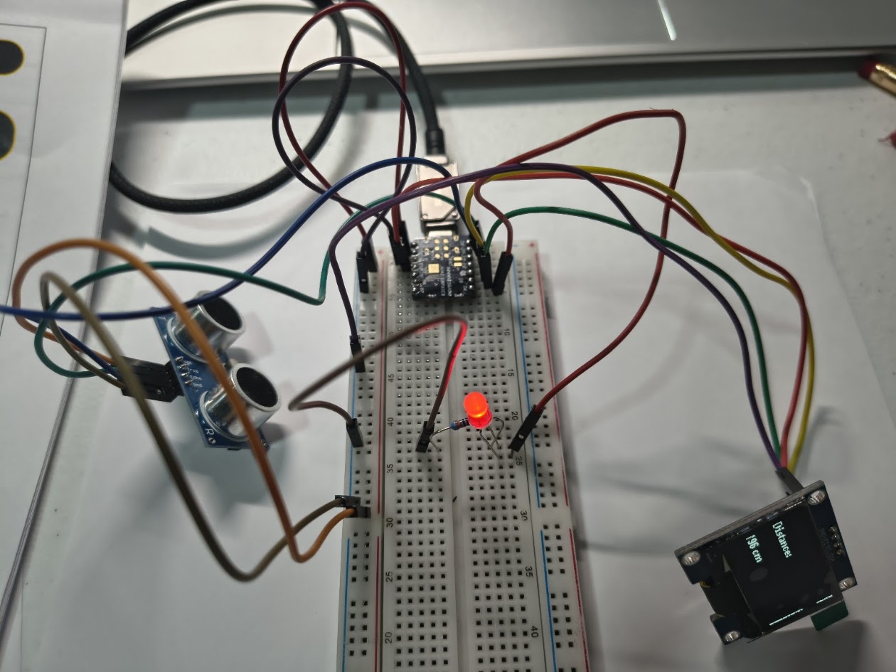
- Included a 'hero shot' of your board
7) References files
We learn how to design, make and test a PCB with sensor. Files: in each section