
Week 17 | Wildcard Week
Wildcard Week – Fiber Laser Engraving and Cutting
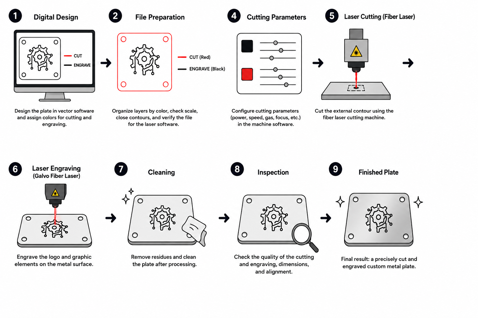
The objective of this week was to explore a digital fabrication process different from the ones used in previous assignments. For this activity, a custom stainless steel plate was designed, manufactured, engraved, and cut using fiber laser technologies.
Unlike processes such as FDM 3D printing, CO₂ laser cutting, or CNC milling, fiber laser systems allow high-precision fabrication on metallic materials through concentrated laser energy. Depending on the machine configuration, the process can be used for permanent surface engraving, detailed marking, or full material cutting with high dimensional accuracy.
This assignment focused on understanding the complete workflow from digital design and file organization to machine setup, parameter calibration, fabrication, and final finishing.
Two independent machines were used during the process:
- A fiber laser cutting machine for manufacturing the external geometry of the plate.
- A galvo fiber laser machine for engraving logos and graphic elements on the metal surface.
1. Selected Process
The selected process combined fiber laser cutting and fiber laser engraving. Both technologies use a highly concentrated laser beam, but each one is optimized for different fabrication purposes.
The cutting machine was used to produce the external stainless steel geometry with precise dimensional control, while the galvo laser system was used to engrave permanent graphic details onto the metal surface.
Depending on parameters such as power, speed, frequency, focus position, and hatch configuration, the laser can generate different fabrication results including surface marking, deep engraving, partial penetration, or full cutting through the material.
For this assignment, the workflow combined:
- Digital vector design preparation.
- Laser cutting of the external contour.
- Laser engraving of logos and graphics.
- Material cleaning and inspection.
- Validation of dimensional accuracy and surface finish.
The project also allowed experimentation with the relationship between fabrication precision and visual aesthetics, combining functional manufacturing with graphic surface finishing.
2. Plate Design
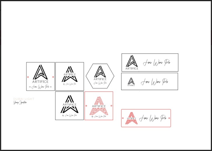
The plate design was created digitally in Adobe Illustrator. The composition included both the graphic information intended for engraving and the external geometry required for cutting.
The design contained two main categories of elements:
- Graphic elements and text for laser engraving.
- External contour lines for laser cutting.
Several design iterations were developed during the process in order to evaluate different visual compositions and layout configurations. These explorations included modifications in:
- Logo size and positioning.
- Text alignment and hierarchy.
- Spacing between graphic elements.
- Overall visual balance.
- Relationship between engraved graphics and the external metal geometry.

During the design stage, the following aspects were considered:
- General dimensions of the plate.
- Legibility of text and graphic elements.
- Minimum spacing between engraved areas and cutting contours.
- Line thickness and engraving readability.
- Position and continuity of the external contour.
- Visual integration between geometry and engraved details.
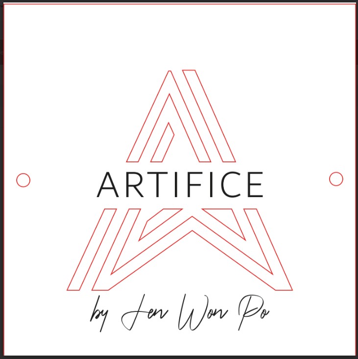
3. File Preparation
Before fabrication, the vector file was organized and optimized to ensure compatibility with both laser systems and to avoid fabrication errors during cutting and engraving.
The preparation process included:
- Separating engraving and cutting operations using different layer colors.
- Verifying that all cutting contours were completely closed.
- Removing duplicated or overlapping geometries.
- Checking dimensional accuracy at real scale.
- Aligning graphic elements with the external geometry.
- Confirming compatibility with the laser machine software.
This preparation stage was critical because even small vector errors could generate incorrect toolpaths, alignment problems, or fabrication inconsistencies during the laser process.
Proper file organization also simplified the transition between the cutting machine and the engraving machine, improving workflow efficiency and reducing setup errors.
4. Metal Fabrication Process: Laser Cutting and Laser Engraving
For the fabrication of the metal component used in the project, two different machines were utilized as part of a combined digital manufacturing workflow. The first machine was used for cutting the stainless steel geometry, while the second machine was used for engraving graphic details and branding onto the metal surface.
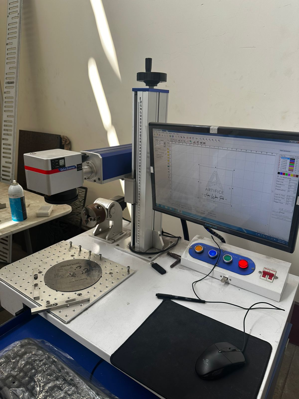
A fiber laser cutting machine was used to manufacture the main geometry of the component, followed by a galvo fiber laser engraving machine used for surface marking and aesthetic finishing.
The workflow was divided into two main stages:
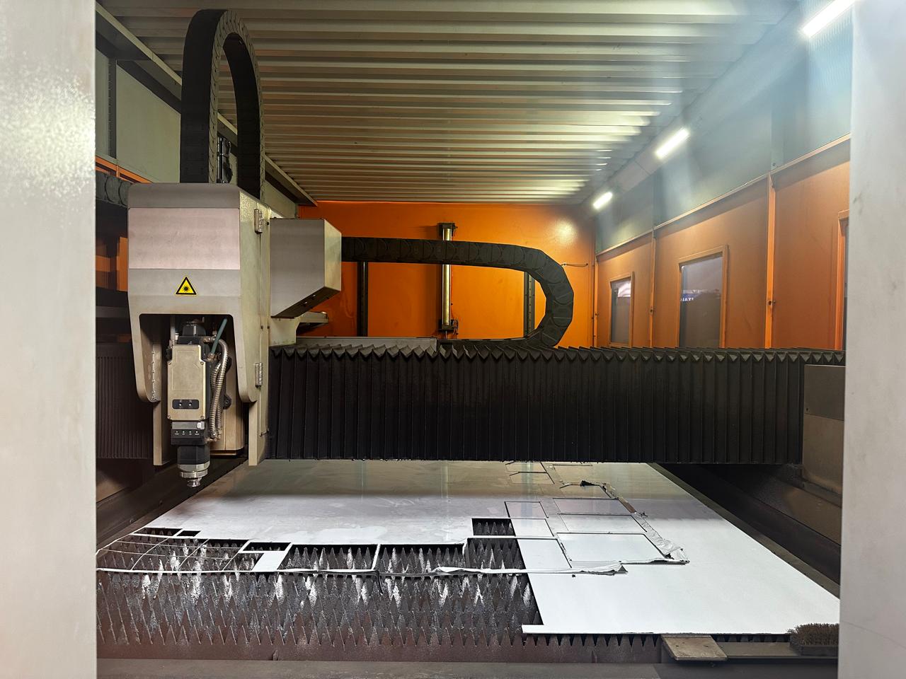
4.1 Laser Cutting Process
Machine Used
A fiber laser cutting machine was used for the fabrication process:
- Brand: Qiaolian Laser
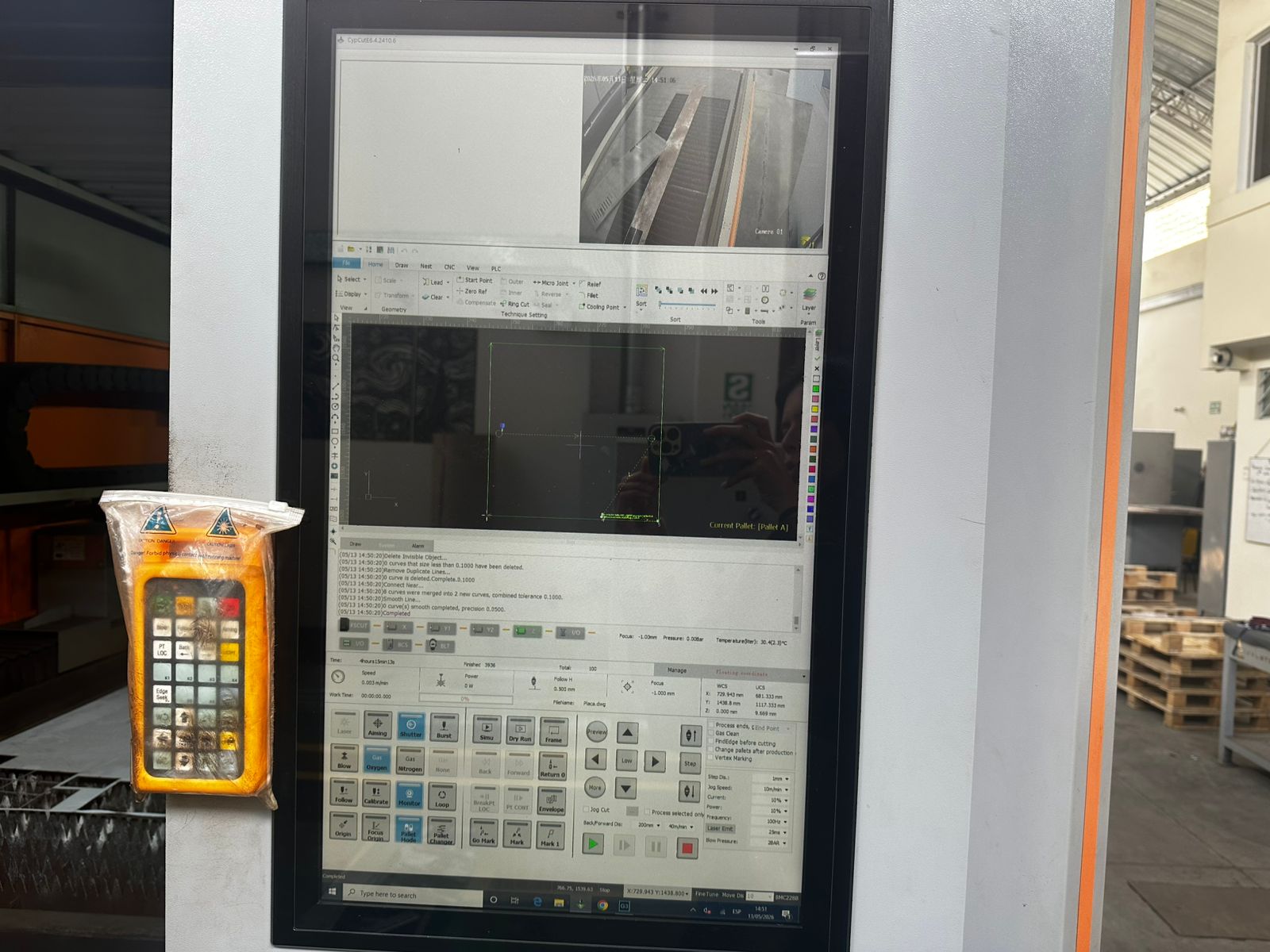
- Software: CypCutE 6.4.2410.6
- Machine Type: Fiber Laser Cutting Machine
- Material: Stainless Steel
- Material Thickness: 2 mm
The design was previously prepared as a vector file and later imported into the CypCut software to configure the cutting paths and manufacturing parameters.
File Preparation
Before starting the cutting operation, several preparation steps were performed inside the software:
- Importing the vector file.
- Correcting open contours.
- Defining cutting start points.
- Applying kerf compensation.
- Configuring internal and external cutting paths.
- Organizing the cutting sequence.
The metal sheet was positioned on the perforated support bed of the machine before starting the operation.
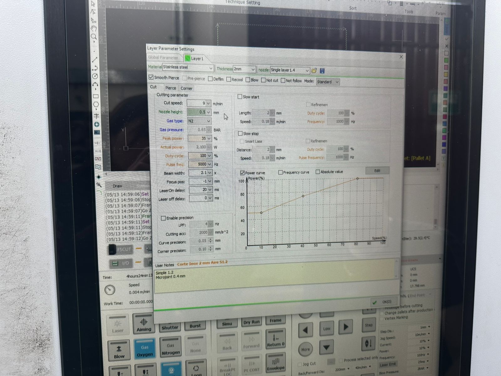
Cutting Parameters
| Parameter | Value |
|---|---|
| Material | Stainless Steel |
| Thickness | 2 mm |
| Cutting Speed | 9 m/min |
| Nozzle Height | 0.5 mm |
| Gas Type | N2 (Nitrogen) |
| Gas Pressure | 0.65 BAR |
| Peak Power | 35 % |
| Actual Power | 2100 W |
| Duty Cycle | 100 % |
| Pulse Frequency | 5000 Hz |
| Beam Width | 2.1 |
| Focus Position | -1 |
| Laser ON Delay | 20 ms |
| Laser OFF Delay | 0 ms |
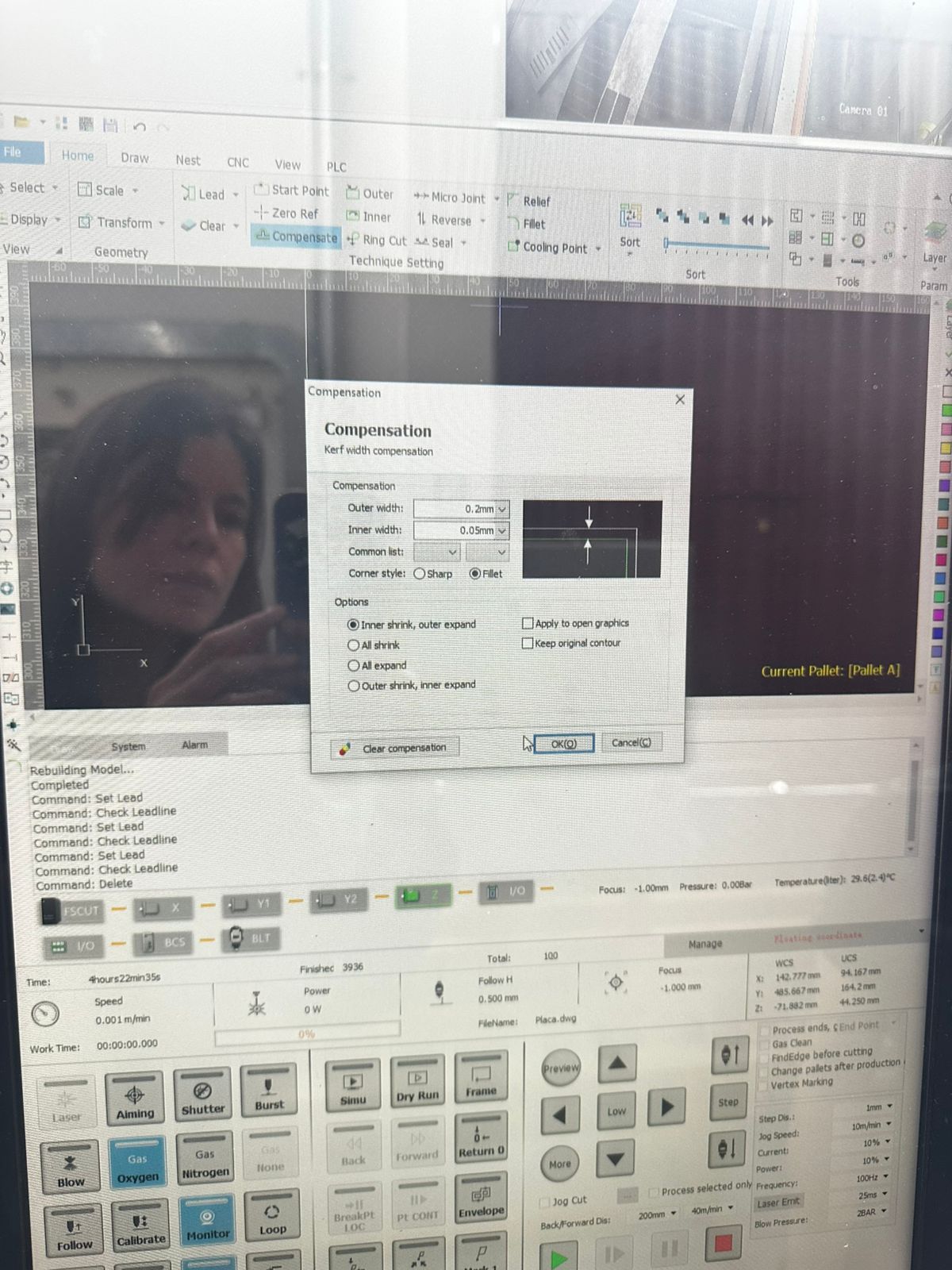
Kerf Compensation Settings
Kerf compensation was applied to maintain dimensional accuracy after the material removal generated by the laser beam.
| Setting | Value |
|---|---|
| Outer Width | 0.2 mm |
| Inner Width | 0.05 mm |
| Mode | Inner shrink, outer expand |
| Corner Style | Fillet |
Technical Considerations
- Nitrogen was used as auxiliary gas to minimize oxidation on the stainless steel edges.
- The nozzle height was kept low to improve cutting precision.
- A negative focus position helped concentrate energy more efficiently through the material thickness.
- Internal contours were cut before external contours to prevent material displacement.
- The software allowed simulation previews before the real cutting process.
Laser Cutting Results
After optimizing the cutting parameters and completing the fabrication process, the resulting metal component showed good dimensional accuracy and surface quality.
- Accurate dimensional cutting of the stainless steel geometry.
- Clean edges with minimal oxidation.
- Good geometric precision in internal and external contours.
- Stable cutting performance across the complete piece.
- Minimal post-processing required after fabrication.
4.2 Laser Engraving Process
Machine Used
A second independent machine was used for the engraving process:
- Machine Type: Fiber Laser Galvo Scanner
- System: Galvo Scanner
- Process: Surface laser engraving on metal
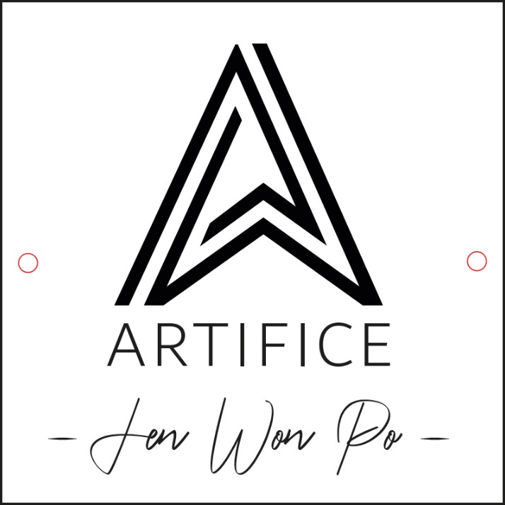
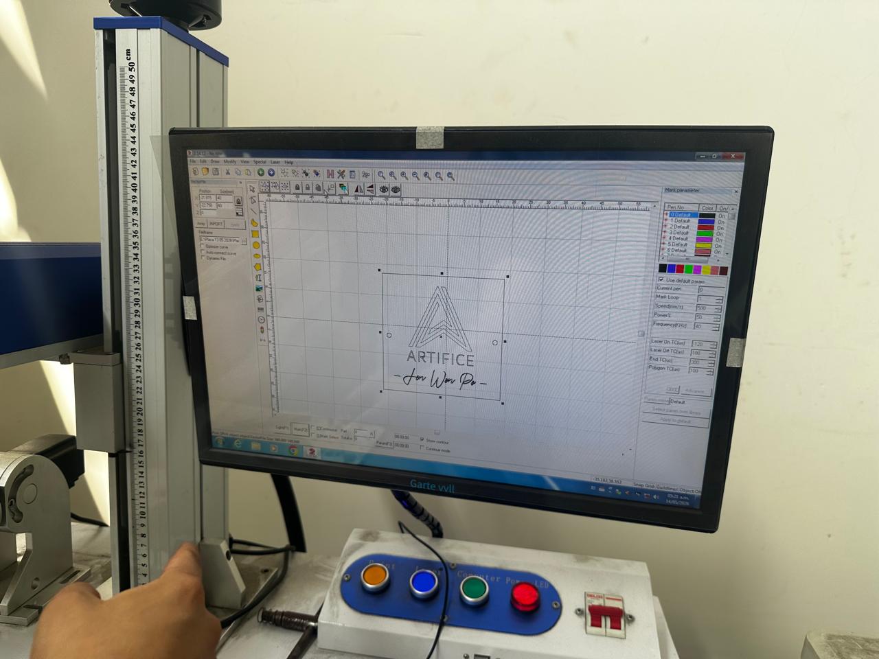
This machine was specifically used to engrave the “ARTIFICE” logo and graphic elements onto the previously cut stainless steel plate.
Engraving Configuration
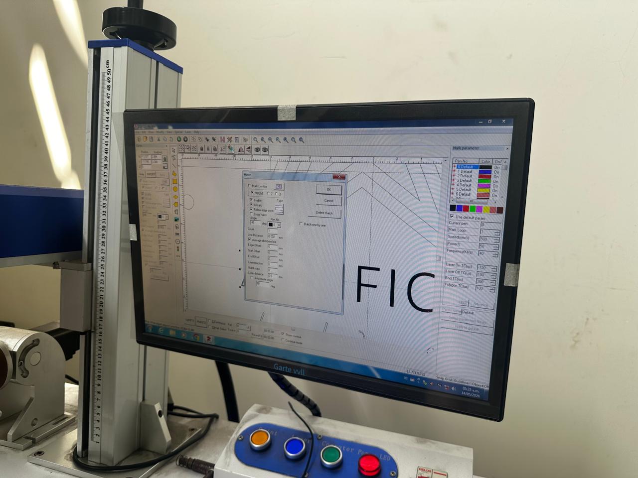
The vector artwork was imported into the galvo scanner software and hatch parameters were configured to define engraving density and texture.
| Parameter | Value |
|---|---|
| Hatch Angle | 45° |
| Line Distance | 0.002 mm |
| Loop Count | 1 |
| Hatch Type | Cross Hatch |
The system allowed a preview of the engraving area before executing the final operation.
Engraving Process
The metal plate was manually positioned and aligned on the work surface using the machine reference system.
The engraving operation was performed after the cutting stage because:
- The final geometry was already defined.
- It reduced alignment errors during engraving.
- The part could be positioned more accurately inside the galvo working area.
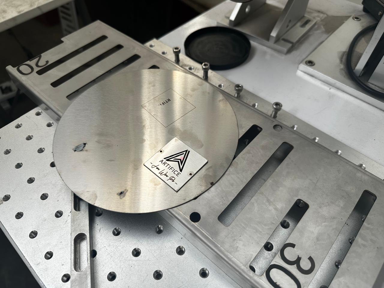
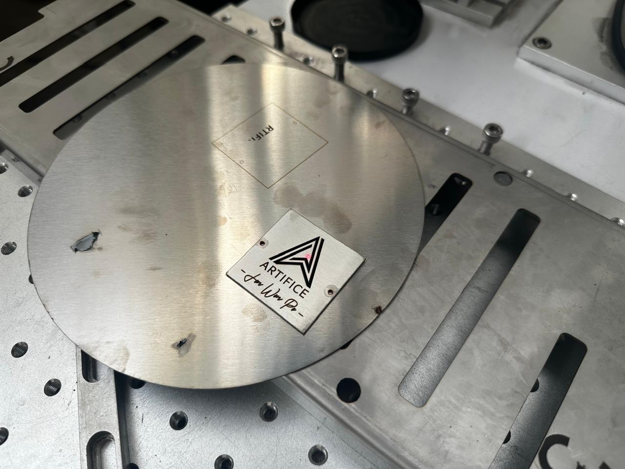
The laser engraved the surface by locally modifying the material finish and generating a permanent visual contrast on the stainless steel.
Laser Engraving Results
- High contrast engraving on the stainless steel surface.
- Permanent marking with good visual definition.
- Precise reproduction of logos and graphic elements.
- Uniform hatch texture across the engraved areas.
- Improved aesthetic quality of the final component.
5. Final Result
The combined workflow allowed the fabrication of:
- A precisely cut stainless steel component.
- Clean and accurate edges.
- Permanent laser engraved graphics.
- A combination of digital manufacturing and aesthetic finishing.
The integration of fiber laser cutting and galvo laser engraving enabled the production of a functional and visually refined metal component with high dimensional precision and surface quality.
6. Difficulties Encountered
Several difficulties were identified during the fabrication process, mainly related to machine calibration, parameter configuration, and alignment between the cutting and engraving stages.
Because two different machines were used, maintaining consistency between both operations required additional preparation and testing.
The main difficulties were:
- Adjusting the laser focus correctly for both cutting and engraving operations.
- Finding the appropriate balance between power, speed, and frequency parameters.
- Avoiding excessive thermal marks and discoloration on the stainless steel surface.
- Achieving sufficient engraving contrast without over-burning the material.
- Correctly separating engraving and cutting layers inside the vector file.
- Preventing small material displacements during handling between machines.
- Aligning the engraved graphics accurately with the previously cut geometry.
- Configuring kerf compensation values to maintain dimensional precision.
Most of these issues were solved through iterative testing, calibration procedures, and progressive parameter adjustments before executing the final fabrication.
7. Key Learnings
- Fiber laser cutting and laser engraving can be integrated into a single digital fabrication workflow.
- Correct file organization is essential to differentiate engraving and cutting operations properly.
- Using separate layers and colors in Illustrator improves workflow organization and machine preparation.
- Laser parameters such as power, speed, frequency, and focus directly affect surface quality and dimensional accuracy.
- Kerf compensation is important to maintain precise dimensions after material removal.
- Nitrogen gas helps reduce oxidation during stainless steel cutting.
- Engraving quality depends strongly on focus calibration and hatch configuration.
- The fabrication sequence is important: cutting first and engraving second improved alignment and handling in this process.
- Small parameter variations can generate visible differences in edge quality and engraving contrast.
- Preliminary tests are necessary before fabricating the final component.
8. Conclusion
The use of fiber laser cutting and galvo laser engraving technologies made it possible to explore an integrated digital fabrication workflow focused on precision manufacturing and permanent surface marking.
By combining two independent machines, the process enabled the production of a stainless steel component with accurate geometry, clean edges, and high-quality engraved graphics.
This activity also helped develop a better understanding of the complete workflow, including vector file preparation, machine configuration, parameter calibration, material testing, cutting optimization, engraving setup, and final validation of the fabricated piece.
The experience demonstrated how digital manufacturing technologies can be combined not only for functional fabrication, but also for aesthetic finishing and product customization.
Download Files
The design files used in this assignment can be downloaded below.