
Week 16 | System Integration
The objective of this week was to integrate all the previously developed subsystems of the project into a single functional prototype. This included the integration of the mechanical structure, electronics, embedded programming, interaction system, power system, and final physical enclosure.
The goal was not only to verify that each subsystem worked independently, but also to evaluate how they function together as a complete interactive system with a more finished and organized appearance.
1. System Overview
The project integrates mechanical movement, embedded electronics, user interaction, and structural components into a single kinetic flower system.
The system operates through the interaction between sensors, actuators, and programmed logic. Motion detected by the PIR sensor activates the servo motor, which controls the opening mechanism of the flower petals.
The complete system includes:
- XIAO ESP32-C3 microcontroller
- PIR motion sensor
- Servo motor
- Push button switch
- LED feedback system
- Battery power system
- Mechanical opening mechanism
- Structural base and enclosure
- 3D printed components
- Embedded programming logic
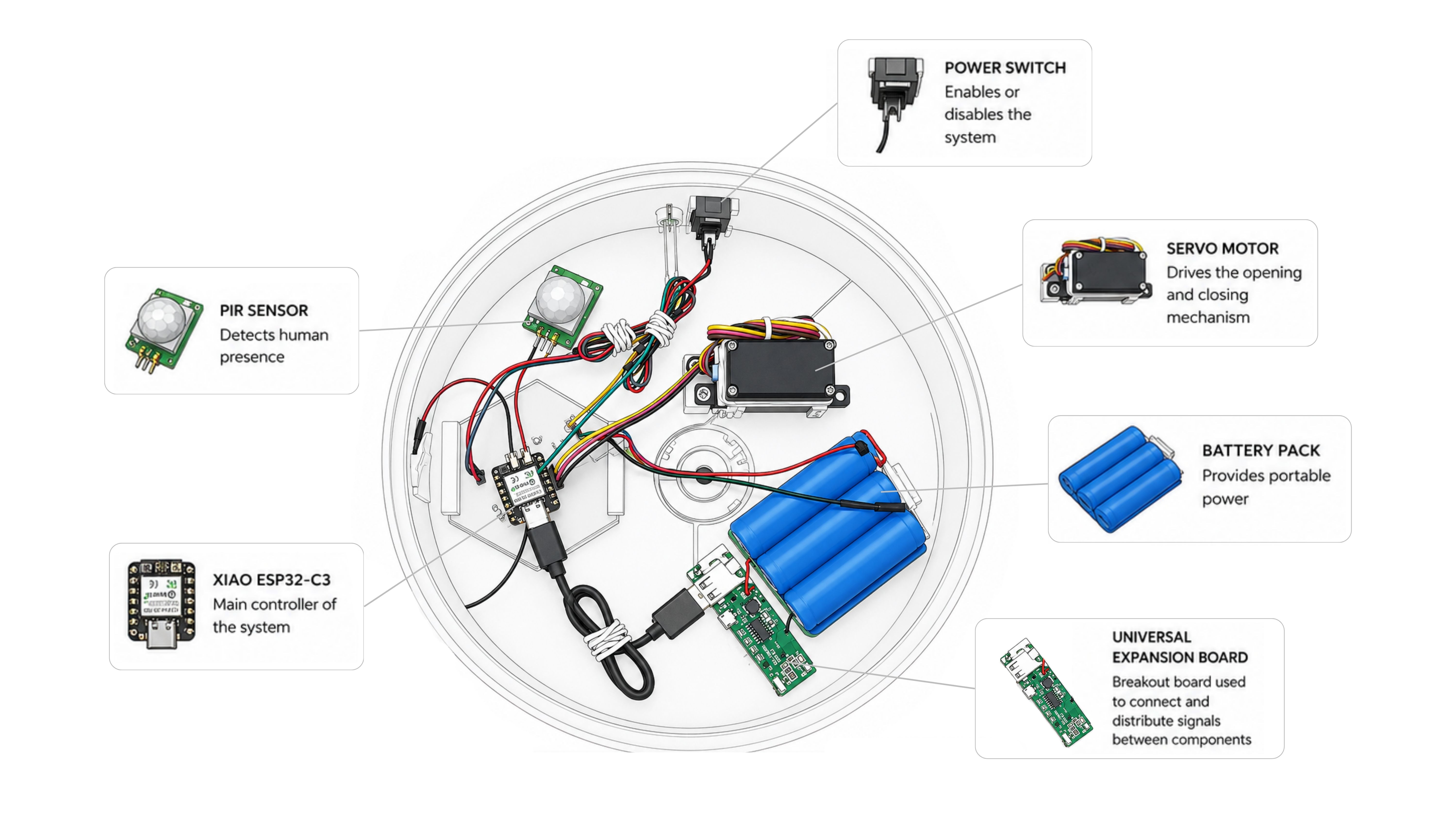
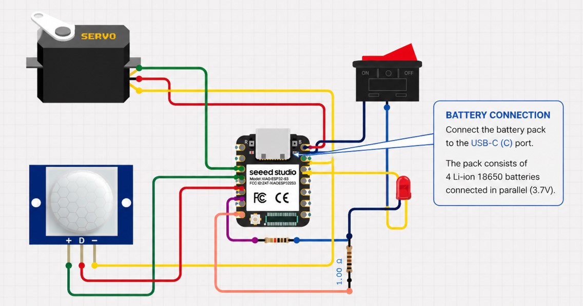
To facilitate the understanding of the integrated system, the main electronic and mechanical elements were mapped according to their position inside the enclosure. The diagram below provides a visual overview of the internal architecture, showing how sensing, control, actuation, and power subsystems are organized and connected within the final prototype.
2. System Logic
The interaction sequence follows this logic:
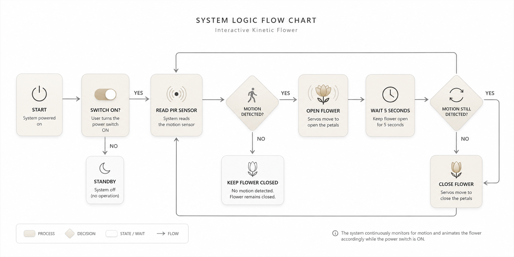
The flowchart illustrates the complete operational sequence of the system. Once the power switch is activated, the controller continuously monitors the PIR sensor. If motion is detected, the servo motor drives the mechanism to open the flower. The system then waits for a predefined period while continuing to monitor the sensor. If motion is still present, the flower remains open; otherwise, the servo returns the mechanism to its initial position and the flower closes. This logic creates a responsive interaction that directly links human presence with the kinetic behavior of the artifact.
The LED provides visual feedback indicating the operational state of the system.
3. Integration Plan
The project was divided into several subsystems that were progressively integrated during the development process.
| Subsystem | Components | Integration Purpose |
|---|---|---|
| Structural System | Base, supports, flower body | Provides stability and houses all components |
| Mechanical System | Servo linkage, moving petals | Converts rotational motion into flower movement |
| Electronic System | PCB, XIAO ESP32-C3, wiring | Controls sensing and actuation |
| Interaction System | PIR sensor, switch, LED | Controls activation and interaction behavior |
| Embedded Programming | Servo control and logic | Coordinates system behavior |
| Power System | Battery and power connections | Provides autonomous power to the system |
The integration process required multiple iterations because modifications in one subsystem frequently affected the others, especially in terms of dimensions, internal space, and movement tolerances.
4. Mechanical and Structural Integration
During this stage, the project evolved from an isolated functional prototype into a more integrated system where the mechanical structure, electronics, interaction components, and power system were considered simultaneously.
Previous prototypes successfully demonstrated the opening and closing mechanism of the flower, as well as the electronic control using the servo motor, PIR sensor, switch, and LED feedback system. However, most of the internal components were still temporarily mounted, exposed, or loosely positioned inside the structure.
Although the mechanism functioned correctly, the assembly lacked stability, cable organization, and a defined internal architecture. Because of this, several modifications were introduced in the final prototype to improve integration and prepare the system for a more finished product appearance.
The base was redesigned considering the real dimensions and positioning requirements of the electronic components. Specific areas were incorporated to organize the internal distribution of the PCB, servo motor, battery, structural supports, and wiring paths.
The redesign process included:
- Internal supports for securing the servo motor.
- Defined positioning for the PCB and electronic connections.
- Space allocation for the battery system.
- Openings and routing paths for cable management.
- Dedicated exit points for the switch and LED.
- Structural elements to improve alignment and assembly stability.
- Additional spacing to facilitate maintenance and future adjustments.
Special consideration was also given to the relationship between the moving mechanism and the enclosure geometry. Since the flower opening system depends on the smooth transmission of movement from the servo to the petals, the placement of each component directly affected the reliability of the system.
A. Base Redesign and Component Integration
The base structure was modified to incorporate the real dimensions and placement requirements of the electronic and mechanical systems.
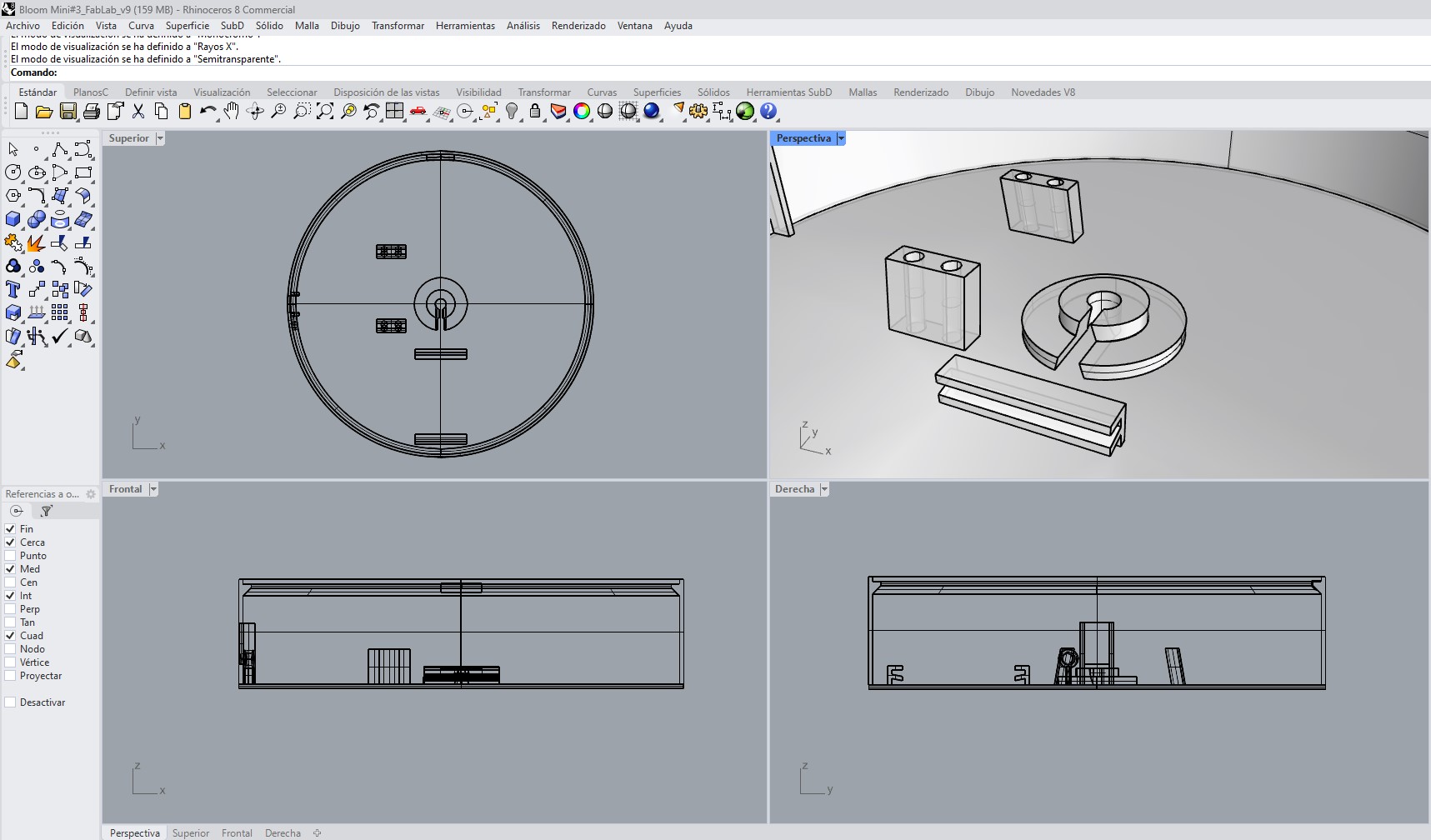
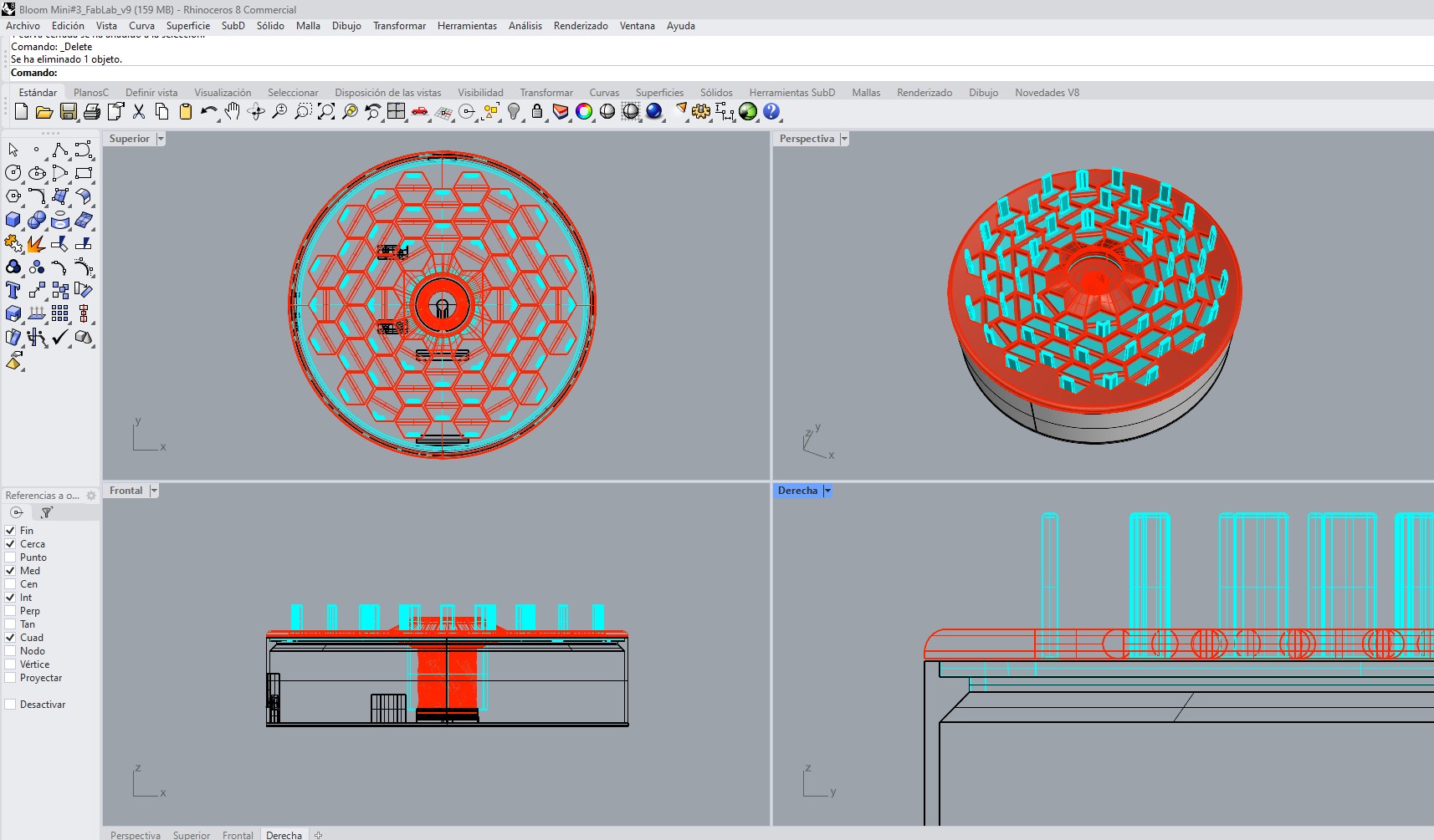
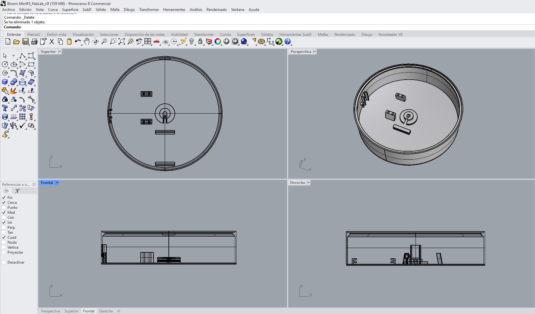 Initial internal layout and component positioning inside the base structure.
B.Internal Supports and Positioning Elements
Additional structural features were designed to secure the servo motor and guide the internal assembly.
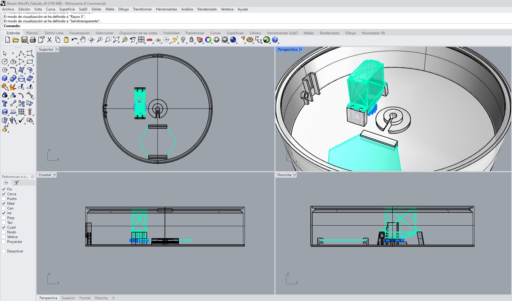 Servo motor positioning and support integration inside the base.
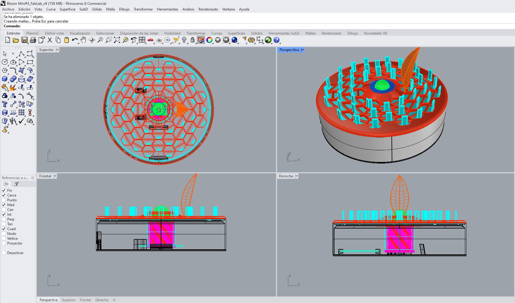
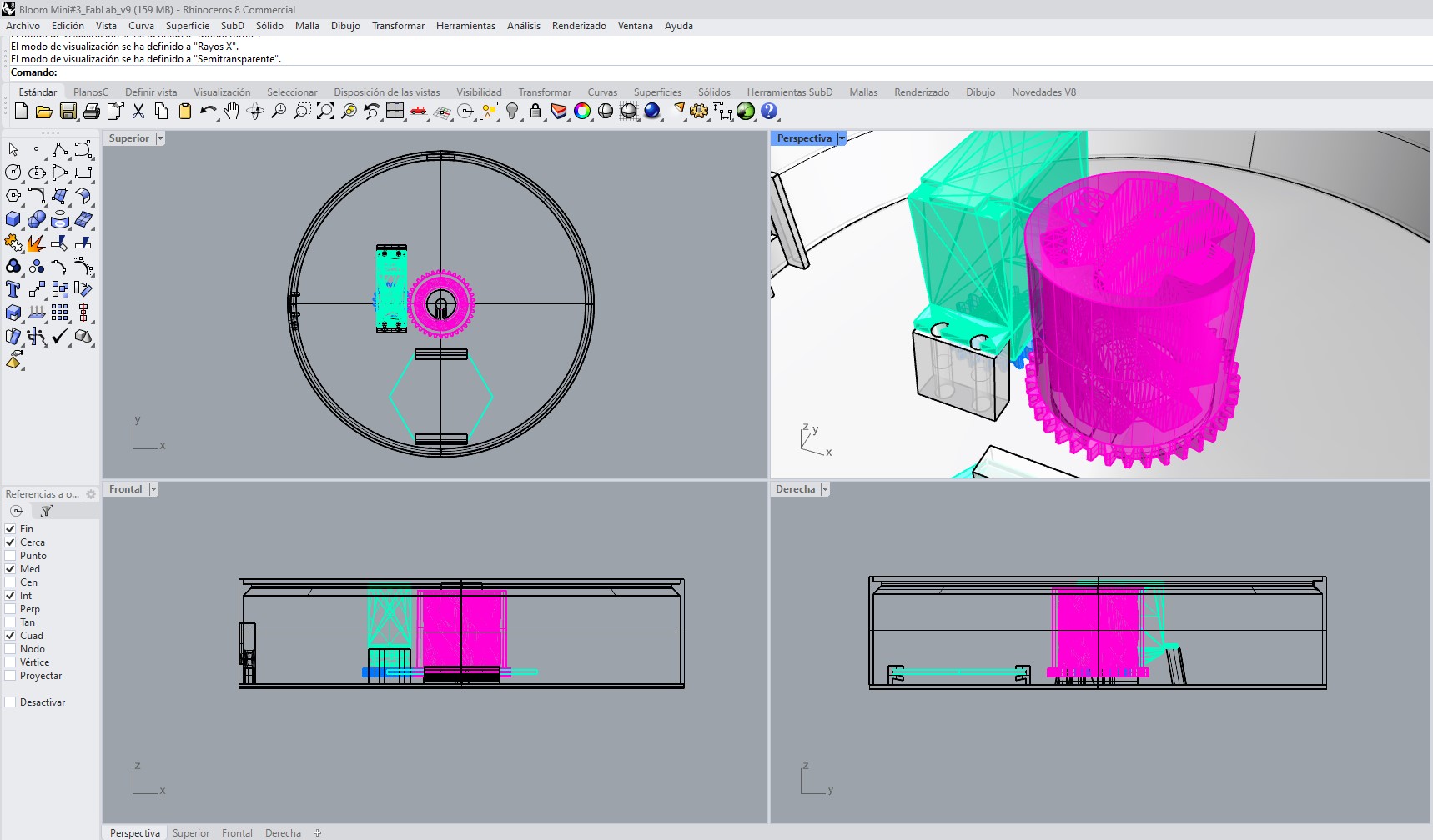 Connection system between the servo gear and the central opening mechanism.
C. Electronic Packaging Considerations
The enclosure design considered cable routing, PCB positioning, battery integration, and external access for interaction components such as the switch and LED.
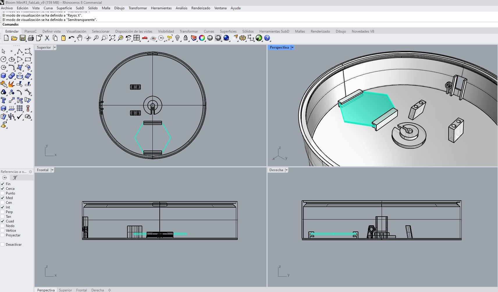
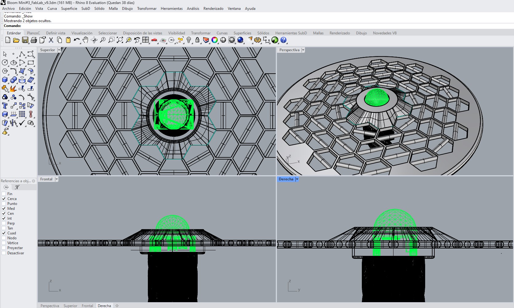
 Central alignment cylinder designed to guide the mechanism and allow internal cable routing.
 PCB positioning and internal electronic support structure.
 Switch and LED mounting features integrated into the enclosure wall.
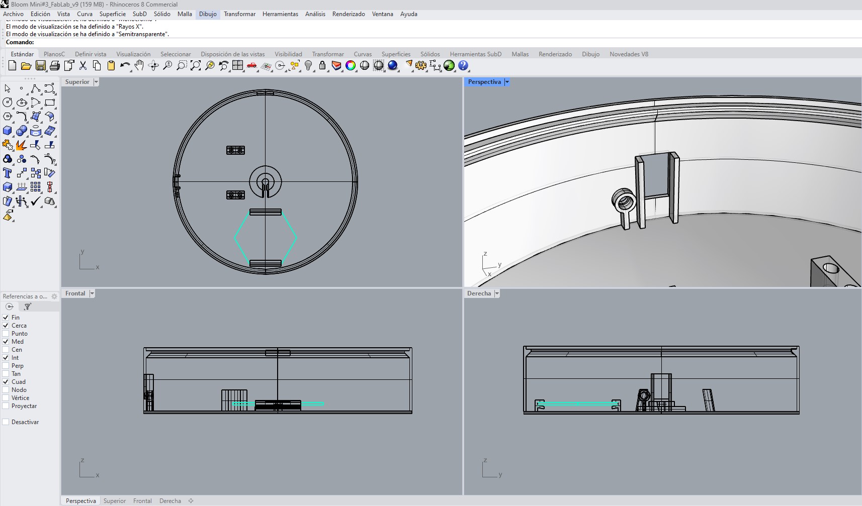
 PIR sensor integration and positioning within the upper structural surface.
D. Structural and Assembly Adjustments
Iterative modifications were performed to improve alignment, reduce interference between components, and achieve a cleaner final integration.
5. Electronics Integration
The electronic system was integrated directly into the redesigned base structure. Unlike previous prototypes where components were externally connected or temporarily fixed, this version considered the electronics as part of the product architecture itself.
The system integrates:
- XIAO ESP32-C3 microcontroller
- PIR motion sensor
- Servo motor
- Push button switch
- Status LED
- Custom PCB
- Battery power system
- Internal wiring connections
One of the main challenges during this phase was organizing the internal space while maintaining accessibility and avoiding interference with the mechanical movement system.
The internal layout was designed to:
- Keep cables protected and organized.
- Prevent collisions with moving components.
- Facilitate assembly and disassembly.
- Improve the visual appearance of the prototype.
- Reduce external exposure of electronic elements.
- Integrate the battery safely within the enclosure.
6. Assembly Process
The assembly process involved the integration of all structural, electronic, and mechanical components into a single functional prototype.
| Stage | Assembly Process | Purpose |
|---|---|---|
| 01 | Structural Base Assembly | Preparation of the main enclosure and internal supports. |
| 02 | Servo and Mechanical Support Installation | Integration of the actuation system and movement supports. |
| 03 | Opening Mechanism Integration | Connection between the servo system and central flower mechanism. |
| 04 | PCB and Electronics Mounting | Installation of the control board and electronic components. |
| 05 | Battery System Integration | Incorporation of the portable power supply inside the enclosure. |
| 06 | Cable Routing and Organization | Internal distribution and management of wiring connections. |
| 07 | Switch and LED Installation | Integration of the external interaction interface. |
| 08 | Petal Placement and Alignment | Assembly and calibration of the flower structure. |
| 09 | Embedded Code Upload and Testing | Verification of programmed system behavior. |
| 10 | Final Functional Verification | Validation of the complete integrated prototype. |
Several assembly iterations were necessary to adjust tolerances and ensure smooth movement of the petals without interference from cables or structural components.
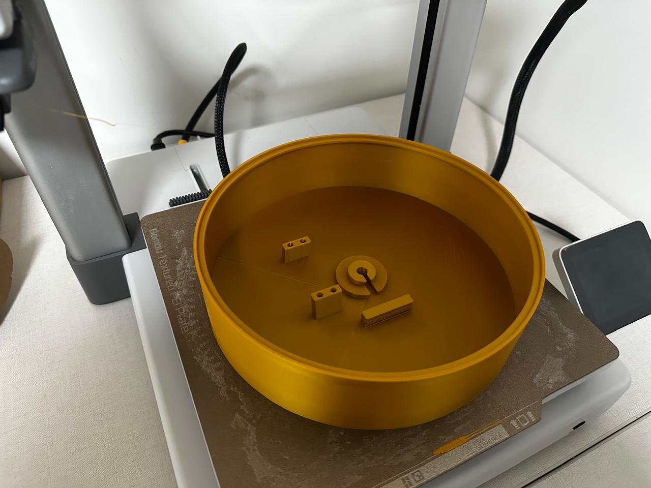
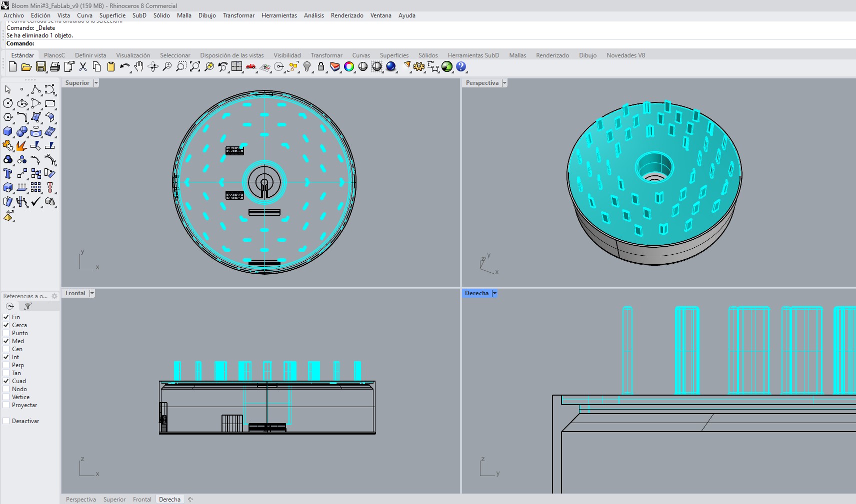
3D printed enclosure base with integrated mounting features designed to accommodate the electronic and mechanical components. Dedicated supports, alignment guides, and component holders were incorporated to ensure accurate positioning, simplify assembly, and improve the overall integration of the system.
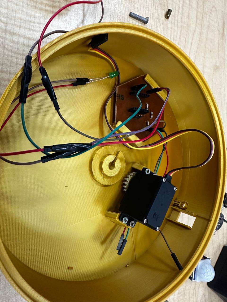
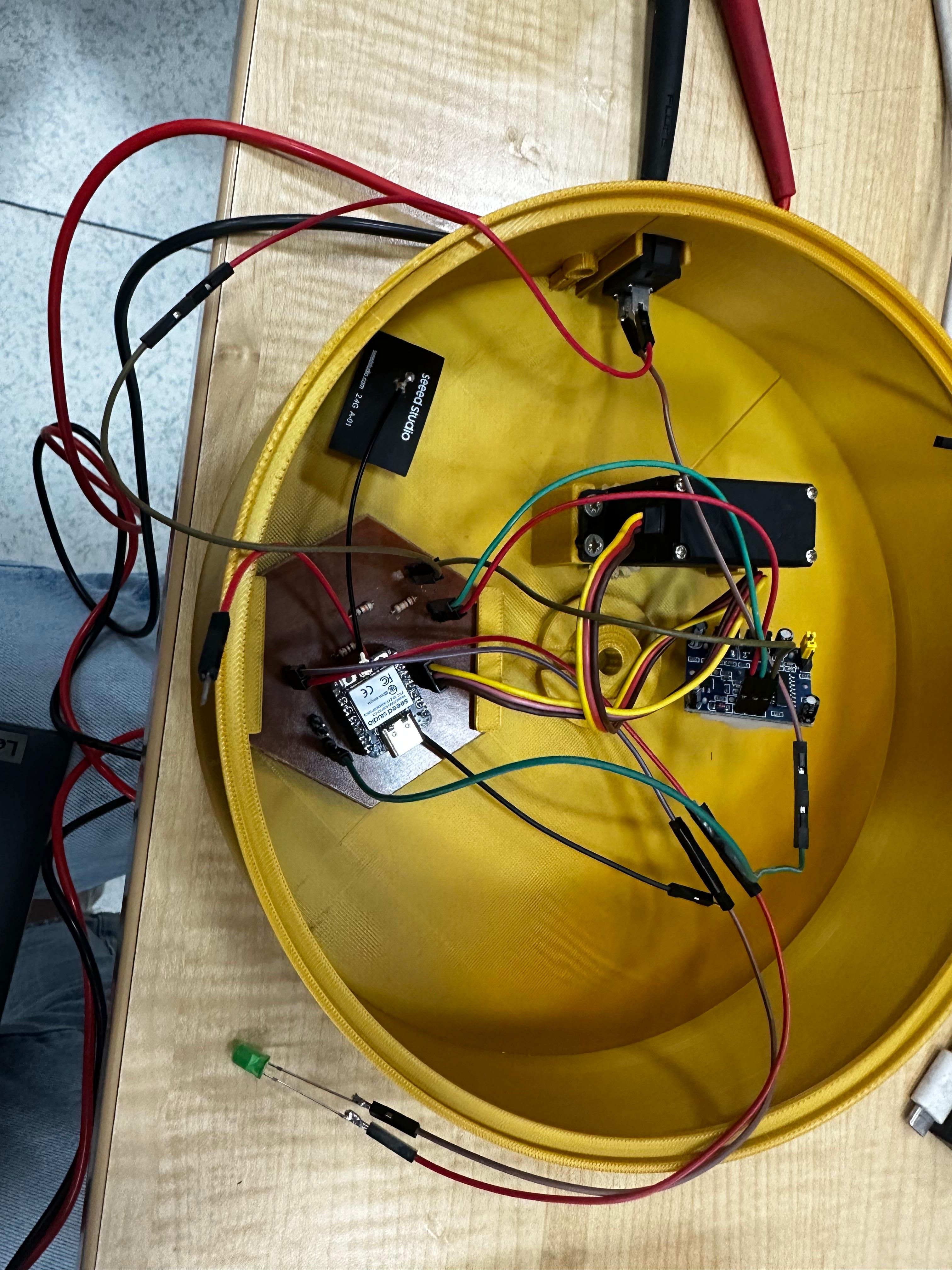
Installation of the control electronics, servo motor, and status LED inside the enclosure. This stage established the connection between the embedded control system and the actuation mechanism, allowing motion commands generated by the microcontroller to be translated into mechanical movement while providing visual feedback of the system status.
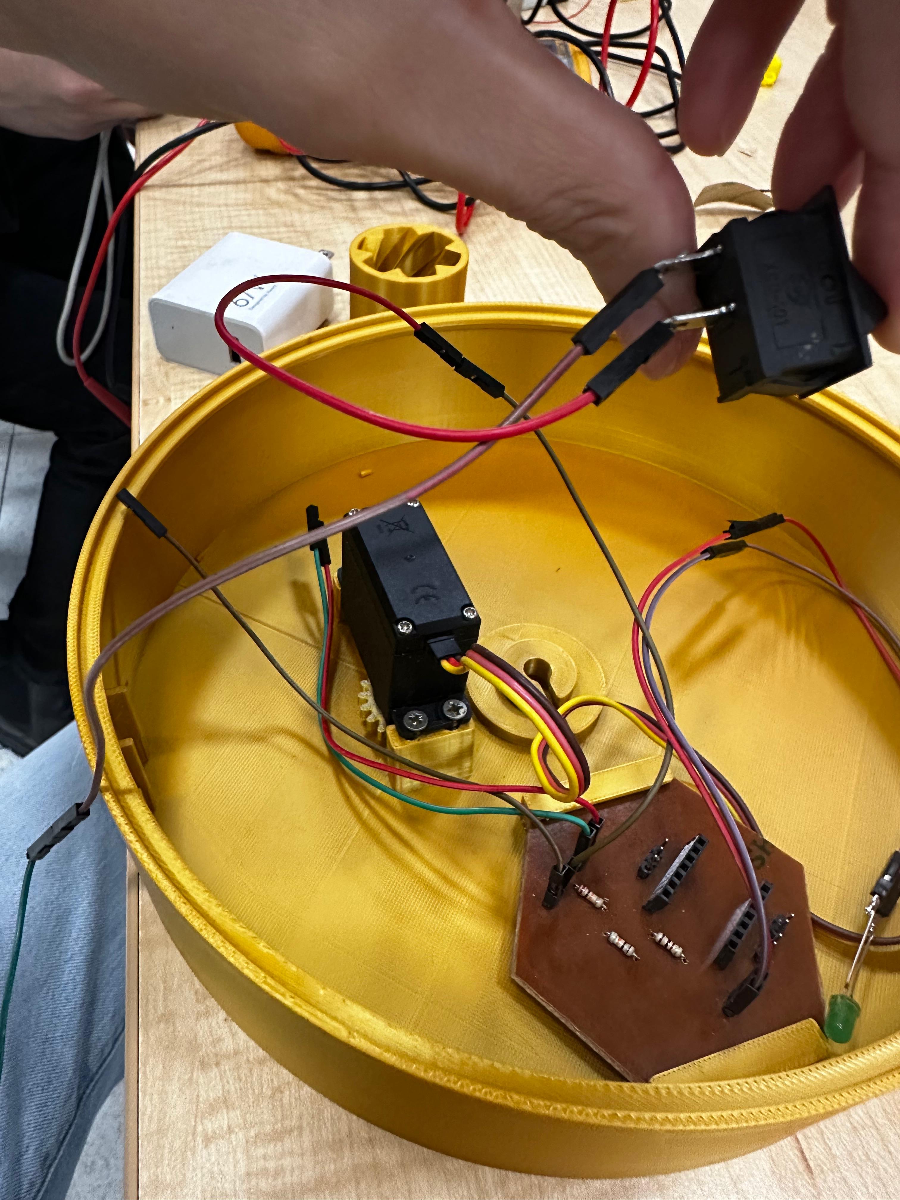
Installation of the power switch used to activate and deactivate the system. The switch was mounted on the enclosure wall to provide easy external access while maintaining a secure connection to the internal electronics and power distribution system.
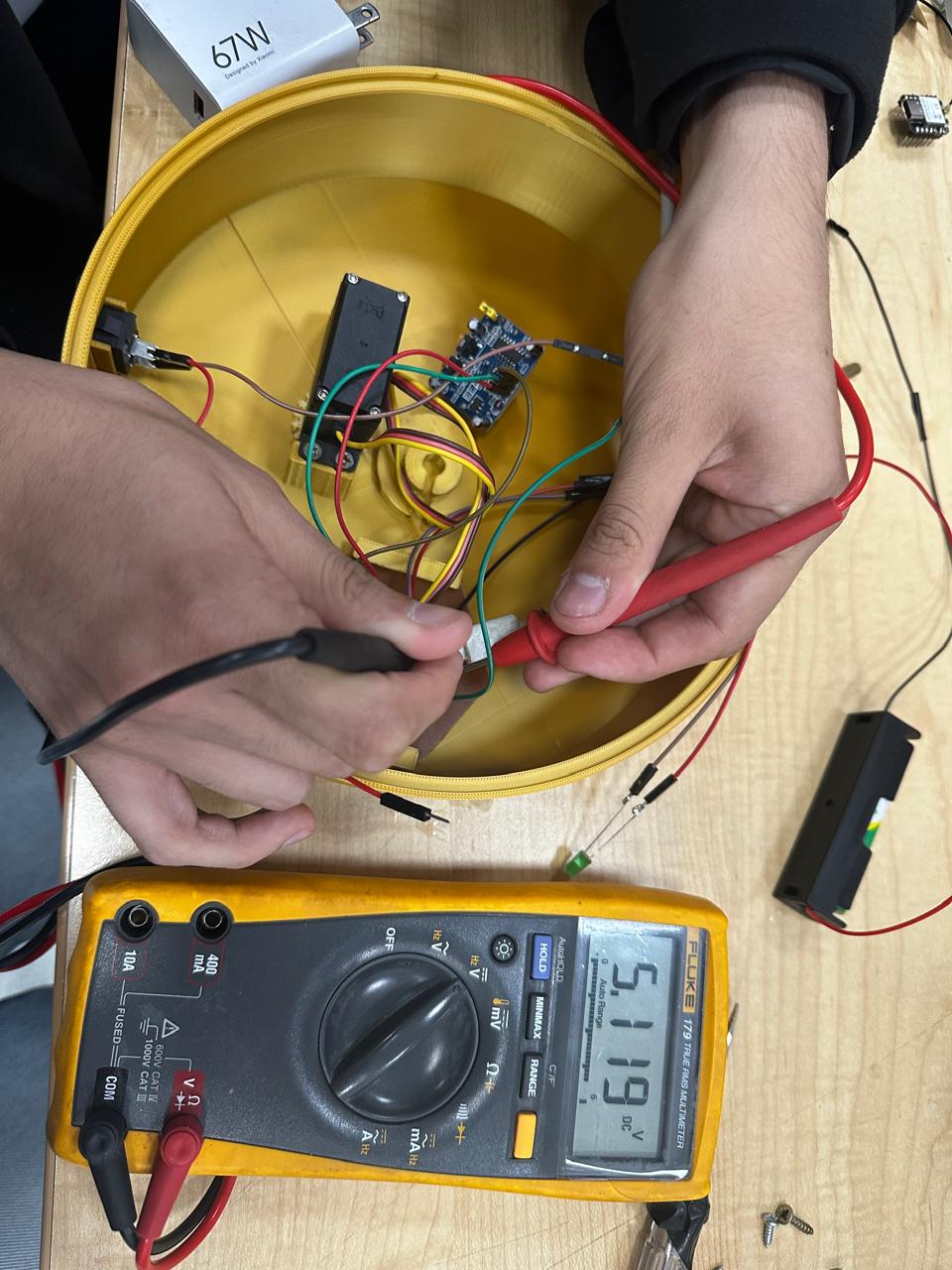
Installation of the PIR motion sensor and verification of the electrical connections using a multimeter. Continuity and voltage measurements were performed to confirm proper wiring, ensure reliable signal transmission, and validate the integration of the sensing subsystem before final assembly.
7. Power Integration
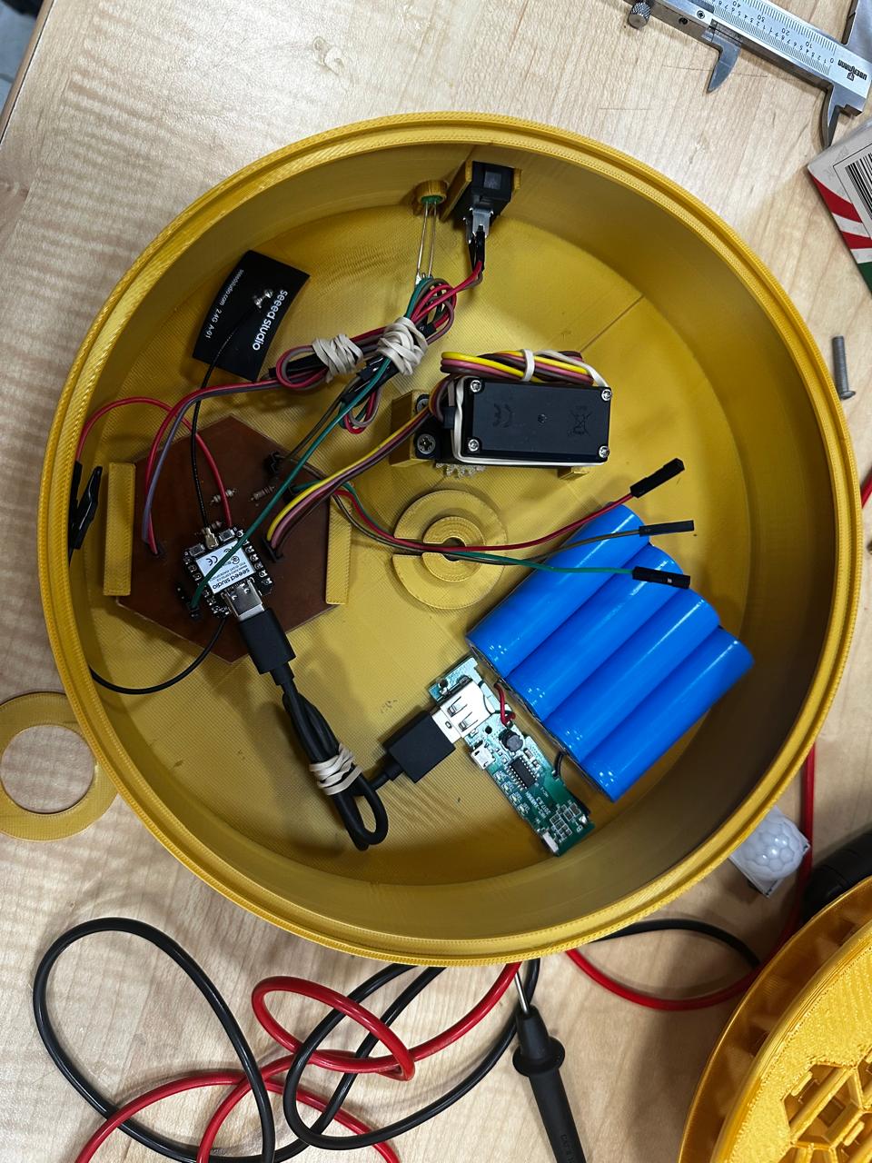
To improve portability and reduce dependence on external wired connections, a battery pack was integrated into the prototype. This allowed the system to operate autonomously while maintaining the functionality of the sensing, control, and actuation subsystems.
The battery was installed inside the enclosure and positioned to optimize the use of the available space while preserving access to the electronic and mechanical components.
The integration of the power system represented an important step toward transforming the prototype from a bench-test setup into a more self-contained interactive object, enabling greater mobility and a cleaner overall assembly.
8. Testing and Adjustments
After completing the integration process, multiple tests were performed to validate the functionality of the entire system.
| Testing Focus | Implemented Adjustments |
|---|---|
| Mechanical movement reliability | Adjustment of servo rotation limits and movement calibration |
| Servo response consistency | Calibration of timing values and optimization of actuation behavior |
| PIR sensor detection behavior | Adjustment of sensor response timing and detection conditions |
| Stability of the petal opening sequence | Optimization of mechanical spacing and reduction of movement interference |
| Structural resistance and alignment | Reinforcement and repositioning of internal structural supports |
| Internal component organization | Modification of cable routing paths and redistribution of internal elements |
| Battery integration and power stability | Redistribution of internal space to accommodate the battery safely |
| Accessibility for maintenance and assembly | Improvement of component positioning and internal accessibility |
The first integration tests were performed with the enclosure open in order to observe the behavior of the mechanism, verify servo movement, evaluate cable interference, and identify possible alignment issues during operation.
Once the mechanical and electronic systems were validated, additional tests were performed with the enclosure closed. During this stage, the electronic components remained outside the structure and the system was powered using an external battery configuration in order to continue evaluating the interaction behavior before completing the final internal integration.
During this stage, the entire system was assembled in an inverted position, with the mechanism oriented upside down to facilitate access to the internal components during testing. However, this configuration introduced significant assembly difficulties, particularly related to cable organization, component accessibility, and structural manipulation. As a result, the internal arrangement was redesigned in the final prototype to simplify the assembly process and improve integration efficiency.
This stage was essential to identify physical constraints that were not evident during isolated subsystem development.
9. Final Integrated Prototype
The final prototype successfully integrates electronics, embedded programming, mechanical movement, interaction systems, portable power, and structural design into a single interactive object.
The project demonstrates:
- Integrated mechanical actuation.
- Embedded electronic control.
- Interactive sensing behavior.
- Portable battery-powered operation.
- Physical system integration.
- Digital fabrication processes.
- Functional prototyping methodologies.
The final system is capable of detecting user interaction and responding through kinetic flower movement controlled by a programmed electronic system.
Although the prototype remains open to future refinements, the current version validates the complete integration of the developed technologies and fabrication processes.
10. Key Learnings
- System integration requires considering mechanical, electronic, structural, and power constraints simultaneously.
- Functional prototypes often require redesign once real component dimensions and assembly requirements are introduced.
- Internal cable organization significantly affects reliability and maintainability.
- Mechanical tolerances directly influence motion quality and system stability.
- Packaging and enclosure design are fundamental parts of product integration.
- Battery integration introduces additional spatial and organizational challenges.
- Interaction systems behave differently under real environmental conditions compared to isolated testing.
- A successful prototype depends not only on functionality, but also on assembly logic, accessibility, and component organization.
11. Final Project Link
For more information about the complete development process of the project, including fabrication, electronics, programming, and prototyping stages, visit the Final Project page.
12. Project Timeline (20 Days of may)
The final phase of the project includes design refinement, fabrication, system integration, and documentation. Additional work was required to complete the petal fabrication and shaping process.
| Task | Day 1-4 | Day 5-8 | Day 9-12 | Day 13-16 | Day 17-20 |
|---|---|---|---|---|---|
| Refine petal design | ● | ||||
| Print remaining petals | ● | ● | |||
| Heat-form petals | ● | ||||
| Adjust central mechanism | ● | ||||
| Servo integration | ● | ||||
| Build final structure | ● | ||||
| System validation | ● | ● | |||
| Process documentation | ● | ● | ● | ||
| Final documentation upload | ● |
The workflow includes overlapping stages, especially during fabrication, integration, and validation. Documentation is developed in parallel to ensure a complete and accurate final submission.