
Week 15 | Interface and Application Programming
Group Assignment
As part of the group work, the focus was on understanding and testing different strategies for interface development and system communication. This included exploring diferents tools for creating graphical interfaces, testing serial communication, and validating how digital interfaces can interact with embedded systems in real time.
For more details about the group work, including testing procedures and results, please visit the group page:
Group assignment documentation
Individual Assignmet
The individual work focused on the design and implementation of an interactive system that connects a Processing interface with a physical mechanism. This included the development of the graphical interface, the integration of serial communication, and the programming of the microcontroller to control a servo motor based on both user input and sensor data.
The system was developed progressively, starting from basic Processing sketches and evolving into a fully functional interface capable of sending commands (OPEN, CLOSE, AUTO) to the microcontroller. Additionally, the hardware configuration, sensor behavior, and system logic were implemented and tested to achieve a responsive interaction.
1. Setup & Installation
Before implementing the system logic, the development environment was installed and configured to enable interface development using Processing.
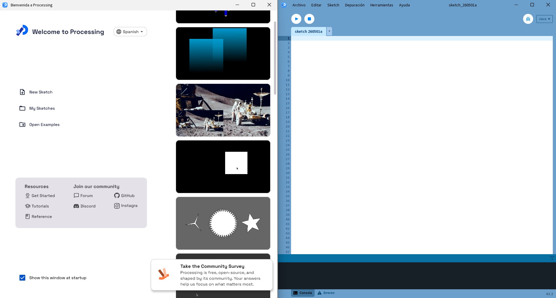
Processing was downloaded from the official website and installed on the system. Once installed, the software was opened and the initial environment was explored, including the interface layout, available examples, and basic sketch structure.
- Processing: Download Processing


A new sketch was created to verify that the environment was working correctly. This step allowed confirming that the software was properly installed and ready for further development.
At this stage, no hardware integration was performed yet. The focus was on preparing the software environment as a foundation for the subsequent development of the graphical interface and system interaction.
2. Interface Development test
Before integrating the system with hardware, an initial exploration was carried out in Processing to understand how the environment works and how to create basic visual outputs.
The process started with simple tests to verify that Processing was correctly installed and running. Basic sketches were created to
understand the structure of the program, particularly the use of the setup() and draw() functions.
These first tests focused on displaying simple shapes on the screen and modifying them to observe how changes in the code affect the visual output. This helped to build a basic understanding of how Processing handles rendering and continuous updates.
At this stage, the goal was not to develop a complete interface, but to become familiar with the tool and validate that it could be used for future interaction development.
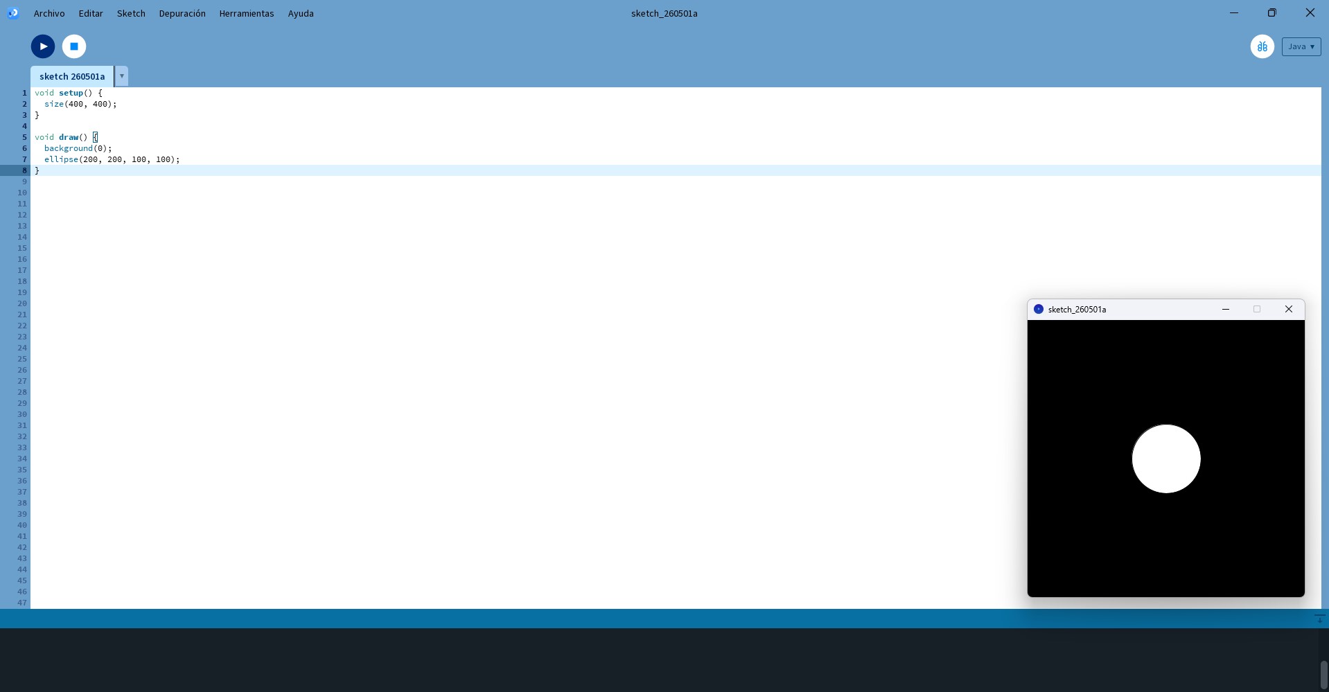
A. Static Sphere Test
A first sketch was created to display a sphere at the center of the screen. This helped to understand the basic structure of Processing,
particularly the roles of setup() and draw().
void setup() {
  size(400, 400);
}

void draw() {
  background(0);
  ellipse(200, 200, 100, 100);
}
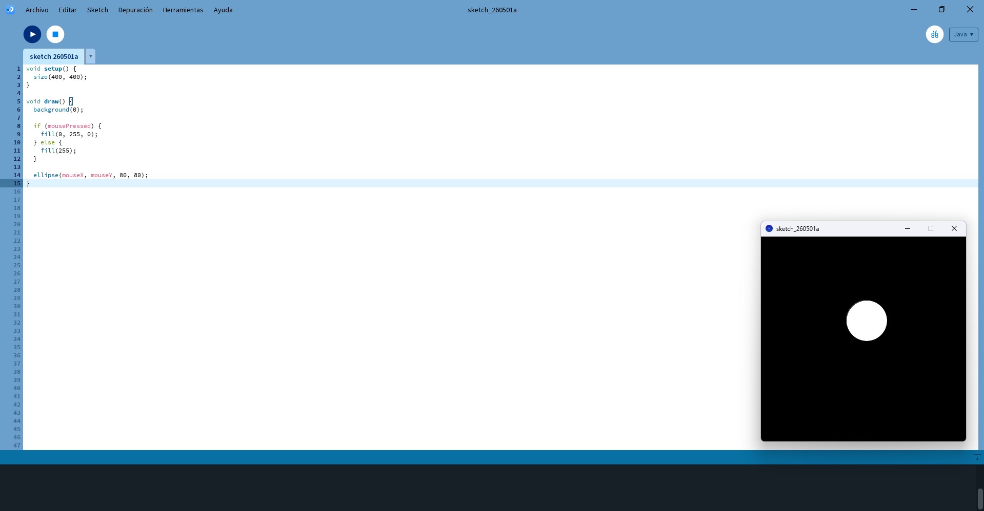
B. Mouse Interaction Test
The sketch was then modified so that the sphere follows the movement of the mouse. This allowed validating real-time interaction and understanding how user input affects visual elements.
void setup() {
  size(400, 400);
}

void draw() {
  background(0);

  if (mousePressed) {
    fill(0, 255, 0);
  } else {
    fill(255);
  }

  ellipse(mouseX, mouseY, 80, 80);
}
The result was:
3. Application Test
After completing the initial tests in Processing, the next step was to develop a simple application to simulate the behavior of the mechanism. The objective was to create a basic interface that could represent two system states: open and closed.
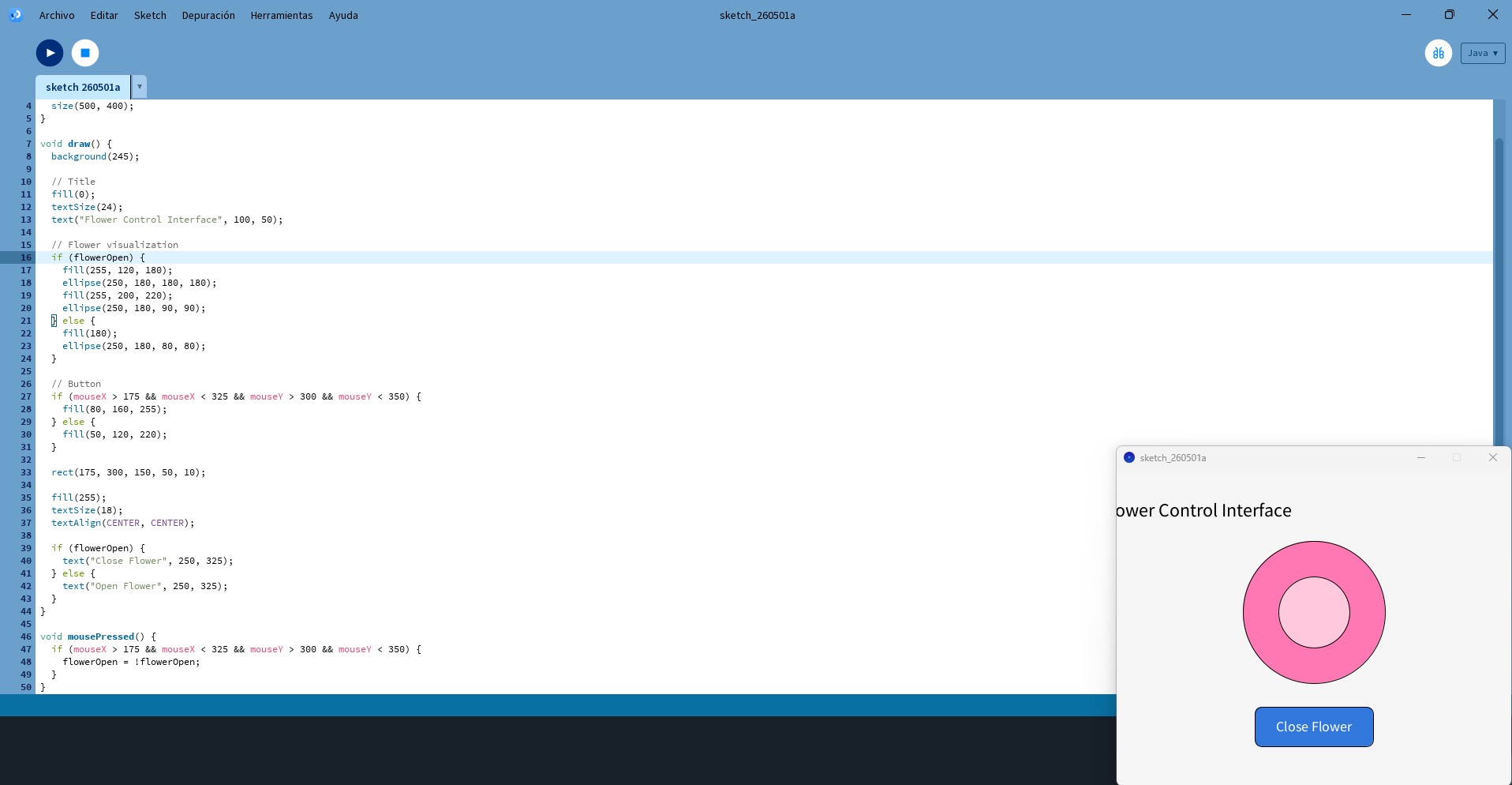
A. First application Test
The first application included a visual representation of the flower mechanism and a button that allowed the user to change its state. When the button was pressed, the interface updated the visual feedback, showing whether the mechanism was open or closed.
This stage helped validate the basic interaction logic before connecting the interface to the microcontroller. It also allowed testing important interface elements such as button detection, state changes, conditional behavior, and visual feedback.
Although this version did not yet communicate with the physical system, it served as a first prototype of the control application and helped define the structure for the final interface.
The code I used:
boolean flowerOpen = false;

void setup() {
  size(500, 400);
}

void draw() {
  background(245);

  fill(0);
  textSize(24);
  text("Flower Control Interface", 100, 50);

  if (flowerOpen) {
    fill(255, 120, 180);
    ellipse(250, 180, 180, 180);
    fill(255, 200, 220);
    ellipse(250, 180, 90, 90);
  } else {
    fill(180);
    ellipse(250, 180, 80, 80);
  }

  if (mouseX > 175 && mouseX < 325 && mouseY > 300 && mouseY < 350) {
    fill(80, 160, 255);
  } else {
    fill(50, 120, 220);
  }

  rect(175, 300, 150, 50, 10);

  fill(255);
  textSize(18);
  textAlign(CENTER, CENTER);

  if (flowerOpen) {
    text("Close Flower", 250, 325);
  } else {
    text("Open Flower", 250, 325);
  }
}

void mousePressed() {
  if (mouseX > 175 && mouseX < 325 && mouseY > 300 && mouseY < 350) {
    flowerOpen = !flowerOpen;
  }
}
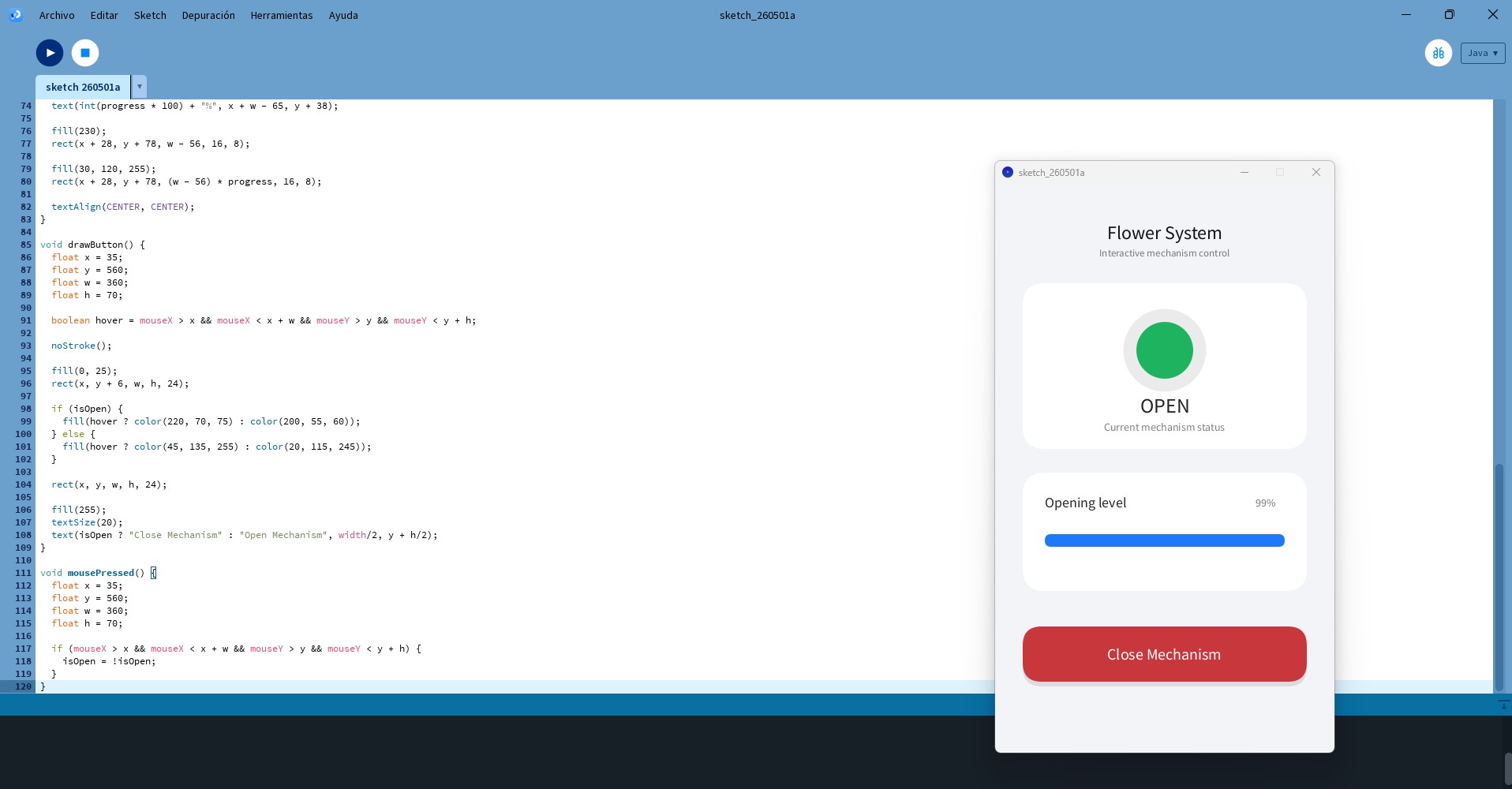
B. Second Interface Prototype
This Processing sketch represents a more advanced interface prototype designed to simulate the behavior of the mechanism without establishing communication with the microcontroller. The goal of this stage was to develop a structured and visually organized interface that mimics the final control system.
Unlike the previous tests, this version introduces a modular interface layout, dividing the screen into functional sections such as system status, progress visualization, and user controls. This allowed organizing the code into reusable functions and improving readability and scalability.
This prototype was used as an intermediate validation step to test interaction logic, interface layout, and visual feedback before integrating serial communication and real hardware control.
boolean isOpen = false;
float progress = 0;

void setup() {
  size(430, 720);
  smooth();
  textAlign(CENTER, CENTER);
}

void draw() {
  background(242, 244, 248);

  float target = isOpen ? 1 : 0;
  progress = lerp(progress, target, 0.08);

  drawPhoneUI();
  drawStatusCard();
  drawProgressModule();
  drawButton();
}
Code Description
The system is based on two main variables: isOpen, which defines the state of the mechanism, and progress, which is used
to generate a smooth visual transition between states. The use of linear interpolation (lerp()) allows simulating gradual motion,
avoiding abrupt changes and providing a more realistic representation of the opening and closing process.
The draw() function continuously updates the interface, refreshing the background, calculating the transition state, and calling
different functions responsible for rendering each part of the interface. This structure replicates how the final system will behave once
connected to the hardware.
4. Hardware Configuration
After validating the interface behavior in Processing, the next step was to define and configure the hardware components required for the physical system. At this stage, the focus was on setting up the electronic elements and verifying their basic functionality before establishing full integration with the interface.
The system integrates the following components:
- Microcontroller: XIAO ESP32-C3
- Sensor: PIR motion sensor connected to digital pin D4
- Switch: Digital input to enable or disable automatic mode connected to D5
- Actuator: Servo motor connected to pin D3
- Feedback: LED connected to digital pin D6 through a current-limiting resistor
The following diagram shows the wiring configuration of the system. It was used as a reference during the assembly and testing process.
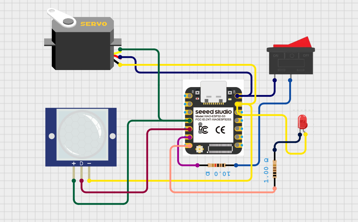
The servo motor is powered and controlled through the microcontroller, receiving its signal from pin D3. The PIR sensor provides digital motion detection input through pin D4. A switch connected to pin D5 allows enabling or disabling the automatic mode, giving control over whether the system responds to sensor input or user commands.
The LED, connected to pin D6 through a resistor, provides visual feedback of the system state, indicating whether the mechanism is active or inactive. All components share a common ground to ensure stable operation.
Each component was individually tested to verify correct operation. This included validating the LED response, checking the movement range of the servo motor, and confirming correct signal readings from both the PIR sensor and the switch.
These preliminary tests ensured that the hardware setup was stable and functional before proceeding to full system integration and communication with the Processing interface.
5. Serial Communication Test
Before using the interface, communication between the microcontroller and the computer was validated through serial communication. This step was essential to ensure reliable data exchange between Processing and the embedded system.
The Arduino Serial Monitor was used to test the connection. Communication was configured at 115200 baud, matching the configuration defined in both the microcontroller code and the Processing environment.
During testing, simple commands were sent and received to verify correct transmission. The system was able to read incoming data and respond accordingly, confirming that the serial communication channel was functioning properly.
Additionally, the correct serial port was identified and verified to avoid connection issues. It was also confirmed that the Serial Monitor must be closed before running Processing, as both applications cannot access the same port simultaneously, which would result in a conflict.
This validation ensured that the system was ready for real-time communication between the graphical interface and the microcontroller.
6. Microcontroller Programming
The microcontroller was programmed to read data from the PIR sensor and control the servo motor and LED accordingly. The system was
designed using a non-blocking approach based on time tracking with the millis() function.
A. Manual Mode – Interface Control
OPEN: The LED turns on and the servo moves to 180°.CLOSE: The LED turns off and the servo moves to 0°.
B. Automatic Mode – Sensor-Based Control
When automatic mode is activated with the AUTO command, the system reads the state of the switch. If the switch is ON,
the LED turns on and the PIR sensor is evaluated. If motion is detected, the servo moves to 180°. If no motion is detected, the servo
returns to 0°. If the switch is OFF, the LED turns off and the servo remains closed.
Arduino Code
#define PIR_PIN D4
#define SWITCH_PIN D5
#define LED_PIN D6

#include <ESP32Servo.h>

Servo myServo;

bool autoMode = false;

void setup() {
  Serial.begin(115200);

  pinMode(PIR_PIN, INPUT);
  pinMode(SWITCH_PIN, INPUT);
  pinMode(LED_PIN, OUTPUT);

  myServo.attach(D3);
  myServo.write(0);
}

void loop() {

  if (Serial.available()) {
    String command = Serial.readStringUntil('\n');
    command.trim();

    Serial.print("Received: ");
    Serial.println(command);

    if (command == "OPEN") {
      autoMode = false;
      digitalWrite(LED_PIN, HIGH);
      myServo.write(180);
    }

    if (command == "CLOSE") {
      autoMode = false;
      digitalWrite(LED_PIN, LOW);
      myServo.write(0);
    }

    if (command == "AUTO") {
      autoMode = true;
      Serial.println("AUTO mode activated");
    }
  }

  if (autoMode) {
    int encendido = digitalRead(SWITCH_PIN);

    if (encendido == 1) {
      digitalWrite(LED_PIN, HIGH);

      int estado = digitalRead(PIR_PIN);

      if (estado == 1) {
        myServo.write(180);
      } else {
        myServo.write(0);
      }
    } else {
      digitalWrite(LED_PIN, LOW);
      myServo.write(0);
    }
  }
}
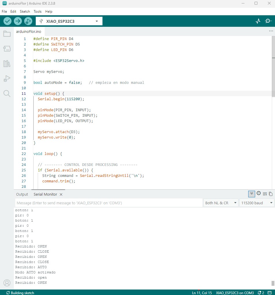
The serial communication between the microcontroller and the computer was validated using the Arduino Serial Monitor.
Commands such as OPEN, CLOSE, and AUTO were sent and successfully received by the system.
The output console shows the received commands and system responses, confirming that the microcontroller correctly interprets incoming data through the serial port at 115200 baud.
7. Technical Implementation
The system is implemented using a continuous loop on the microcontroller that evaluates both serial communication and sensor input. Serial communication enables real-time control from the Processing interface, while conditional logic determines the system behavior depending on the selected mode.
- Immediate response to commands.
- Flexible switching between manual and automatic modes.
- Continuous system evaluation without blocking execution.
Final code
The following code corresponds to the final version of the Processing interface, integrating visual feedback, user interaction, and serial communication with the microcontroller.
import processing.serial.*;

Serial myPort;

boolean isOpen = false;
float progress = 0;

void setup() {
  size(430, 720);
  smooth();
  textAlign(CENTER, CENTER);

  println(Serial.list());
  myPort = new Serial(this, "COM3", 115200);
}

void draw() {
  background(242, 244, 248);

  float target = isOpen ? 1 : 0;
  progress = lerp(progress, target, 0.08);

  fill(20);
  textSize(26);
  text("Flower System", width/2, 60);

  fill(120);
  textSize(14);
  text("Mechanism control interface", width/2, 90);

  drawStatusCard();
  drawProgressCard();
  drawButton(35, 540, 360, 70, isOpen ? "Close Mechanism" : "Open Mechanism");
  drawAutoButton(35, 625, 360, 55);
}
Code Explanation
The Processing sketch implements a graphical interface that communicates with the microcontroller through serial communication, allowing
the user to control the mechanism in real time. The interface uses the processing.serial library, creates a
Serial object, and sends commands such as OPEN, CLOSE, and AUTO to the
microcontroller.
The draw() function continuously renders the interface and updates the progress value using lerp(), creating
a smooth transition between closed and open states. The interface is structured through modular functions for status visualization,
progress display, manual control, and automatic mode activation.
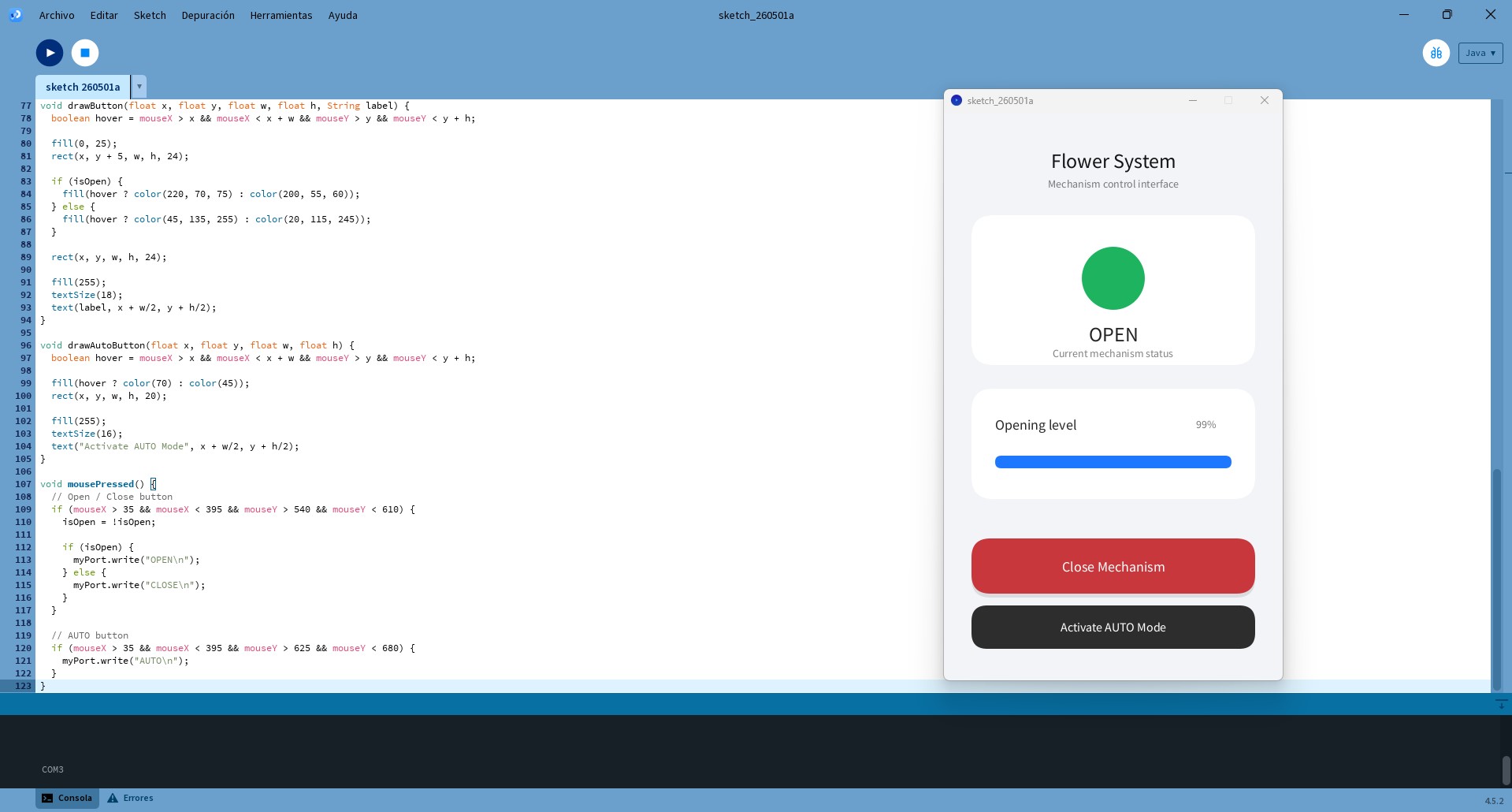
8. Interface Validation
The final interface was tested to verify correct communication with the microcontroller and proper system response.
- Pressing the Open Mechanism button sends the
OPENcommand. - Pressing the Close Mechanism button sends the
CLOSEcommand. - Activating the AUTO Mode button sends the
AUTOcommand.
The interface updates its visual state in real time through text, color, and the progress bar. At the same time, the commands sent through serial communication are correctly interpreted by the microcontroller, resulting in an immediate physical response.
9. Observations and Limitations
During testing, several limitations of the PIR sensor were identified:
- It does not measure distance or continuous presence.
- Detection depends on changes in infrared radiation.
- If the user remains still, detection may stop.
- Performance is affected by environmental conditions.
- It requires an initial stabilization period of approximately 10 to 60 seconds.
10. Design Implications
Although the system appears to respond to user presence—opening the flower when a person approaches and closing it when the person leaves—this behavior is actually based on motion detection rather than continuous presence.
The PIR sensor triggers the system when movement is detected, and the mechanism remains active for a short period. When no further motion is detected, the system returns to its initial state, which can give the impression of presence-based interaction.
However, this behavior depends on movement rather than actual proximity, meaning that if the user remains still, the system may stop detecting them and close the mechanism.
11. Future Improvements
For a more precise and continuous interaction, the PIR sensor could be replaced by a distance-based sensor, such as:
- Ultrasonic sensor HC-SR04
- Time-of-Flight sensor VL53L0X or VL53L1X
if (distance < threshold) {
  open();
} else {
  close();
}
This would enable smoother and more accurate interaction.
Conclusion
The system demonstrates a complete integration between a graphical interface and a physical mechanism. By combining manual control through Processing with automatic sensor-based behavior, the system achieves flexible and interactive actuation.
Despite the limitations of the PIR sensor, the implementation provides a functional and responsive system, with clear opportunities for further refinement.