
Week 14 | Molding and Casting
Group Assignment
As part of the group assignment, we explored the molding and casting process, focusing on material behavior, mixing ratios, and casting techniques. The group work included testing diferent materials properties, evaluating curing behavior, and documenting the overall workflow.
For more details about the group work, including testing procedures and results, please visit the group page:
Individual Assignment
1. Concept and Digital Modeling
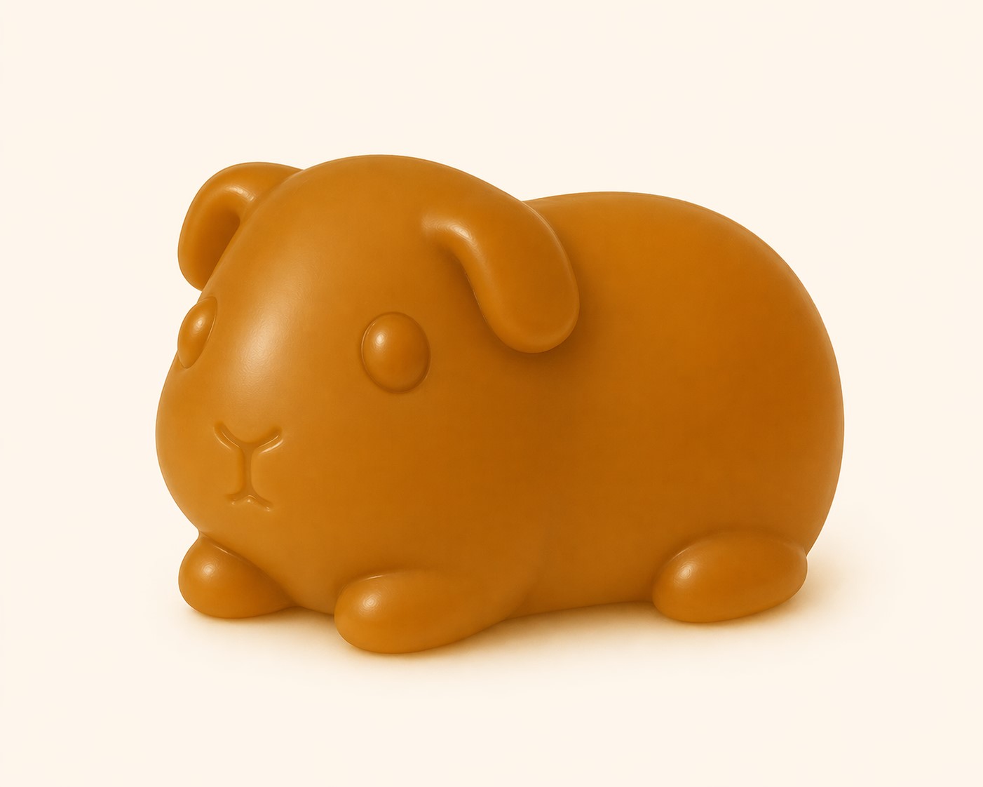
The project starts with the design of a figurative piece: a simplified guinea pig with a “gummy-like” aesthetic. The goal was to achieve a continuous geometry with smooth transitions and large radii, avoiding fine details in order to facilitate both the molding and demolding processes.
The process began by generating a reference image using artificial intelligence (ChatGPT). The prompt used was:
Illustration of a simplified guinea pig, designed in the style of a gummy bear. Rounded, soft, and minimal shape with no realistic details. Single solid color. Small, simple eyes and cute proportions (large head, compact body). No complex textures. Light-colored background, soft studio lighting, clean and modern style.
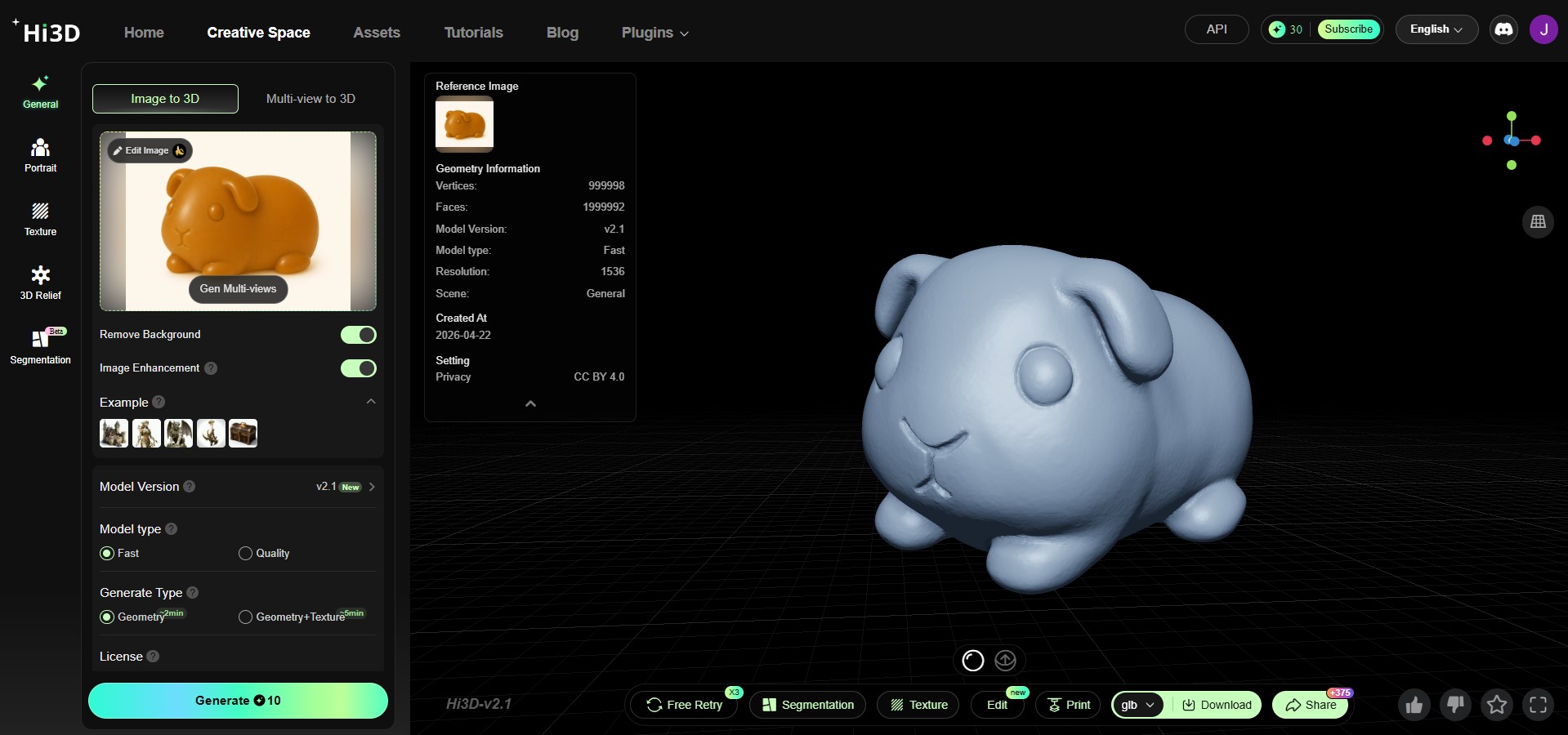
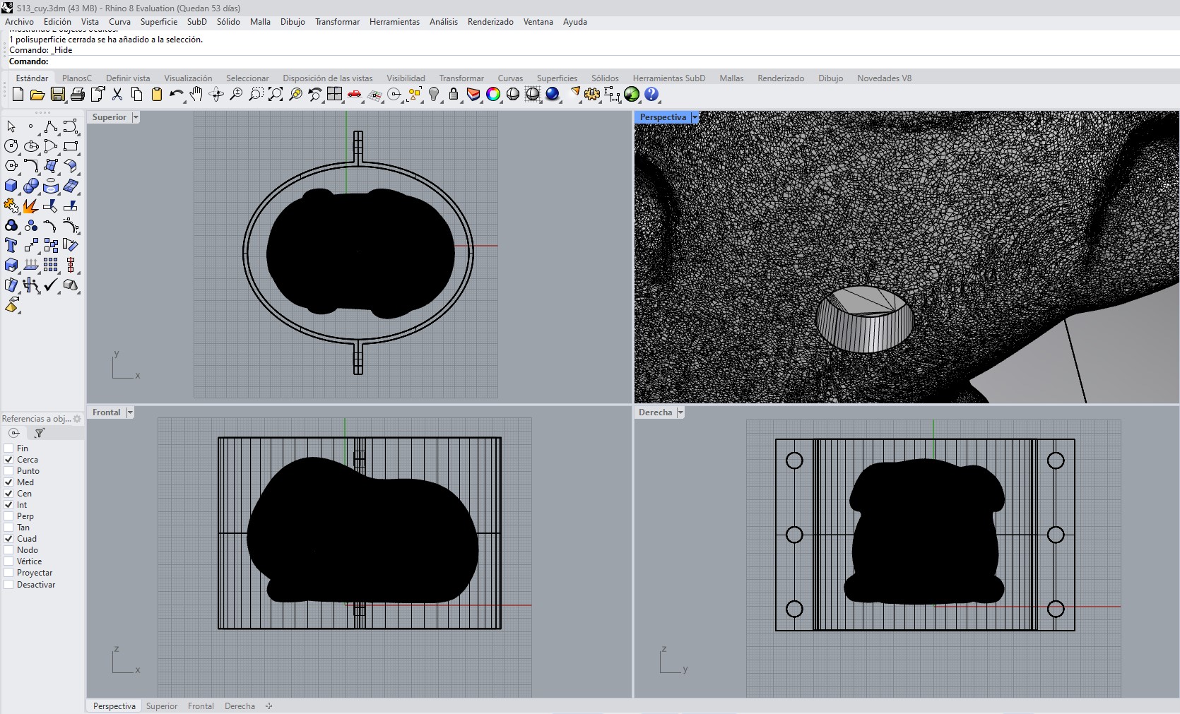
The generated image was then uploaded to Hi3D Creative Space, where it was used as input to generate a 3D mesh of the object. This mesh served as the base geometry for the modeling process.
The generated mesh was downloaded, and the mold was modeled in Rhinoceros 3D. The mold was designed from scratch in CAD, allowing precise control over construction parameters.
2. Mold Design Iteration
2.1 First Mold Design Proposal
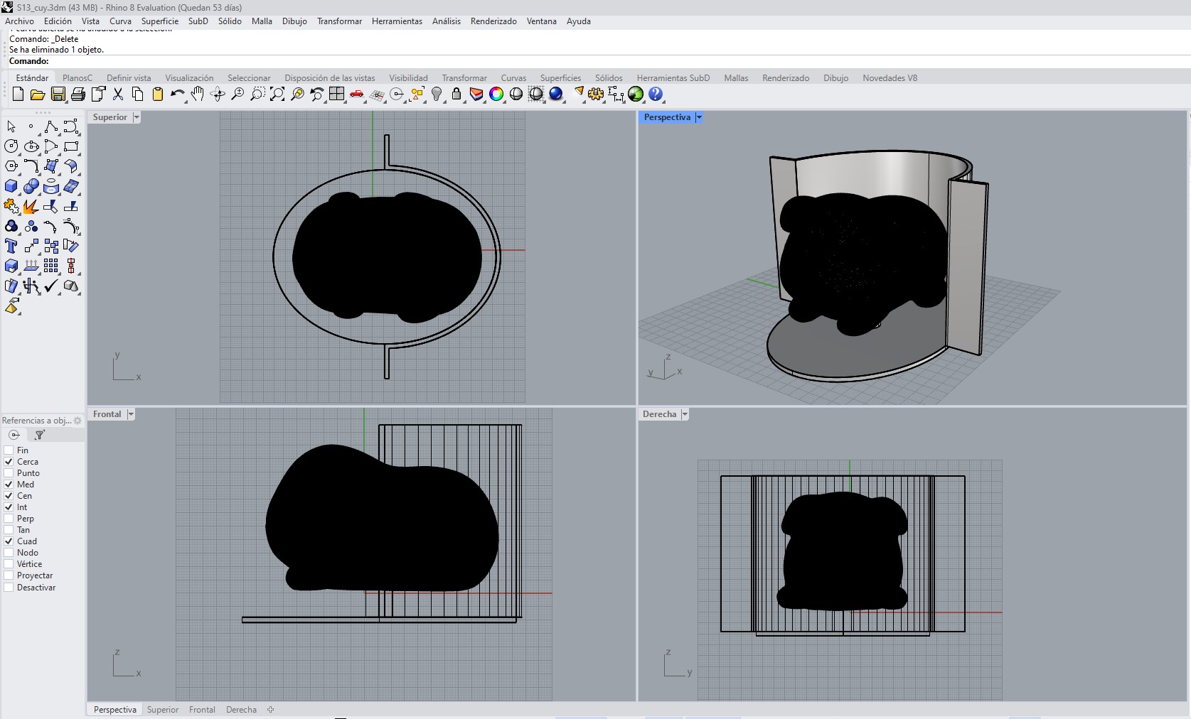
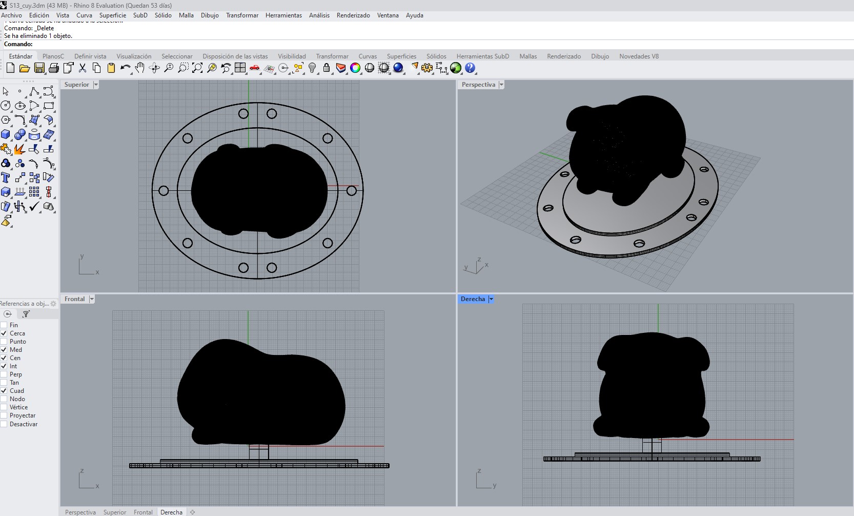
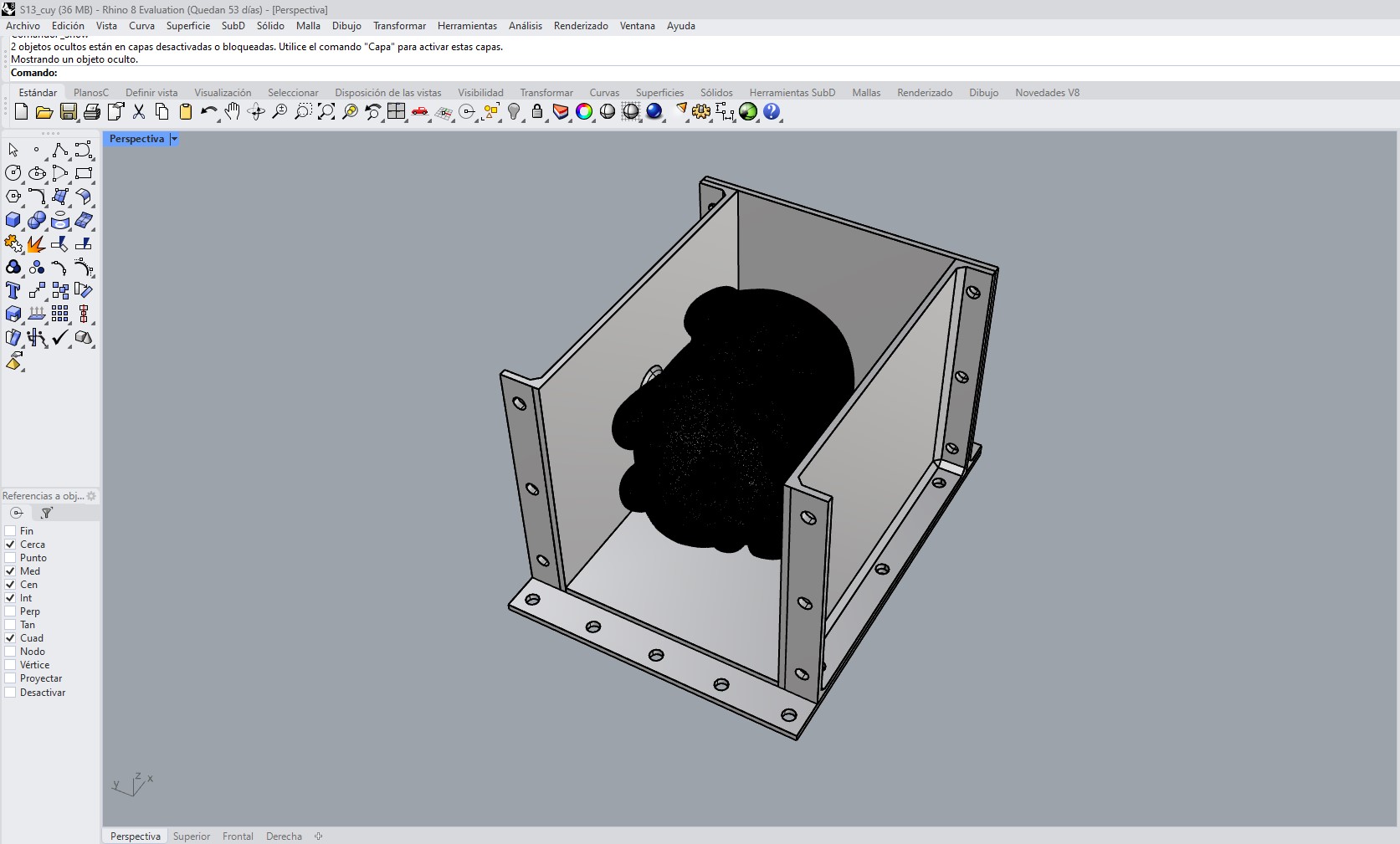
In the first iteration, a single-piece mold was proposed in the form of a cylindrical container. The guinea pig was placed inside this volume, and silicone was poured from the top, creating a monolithic mold surrounding the geometry.
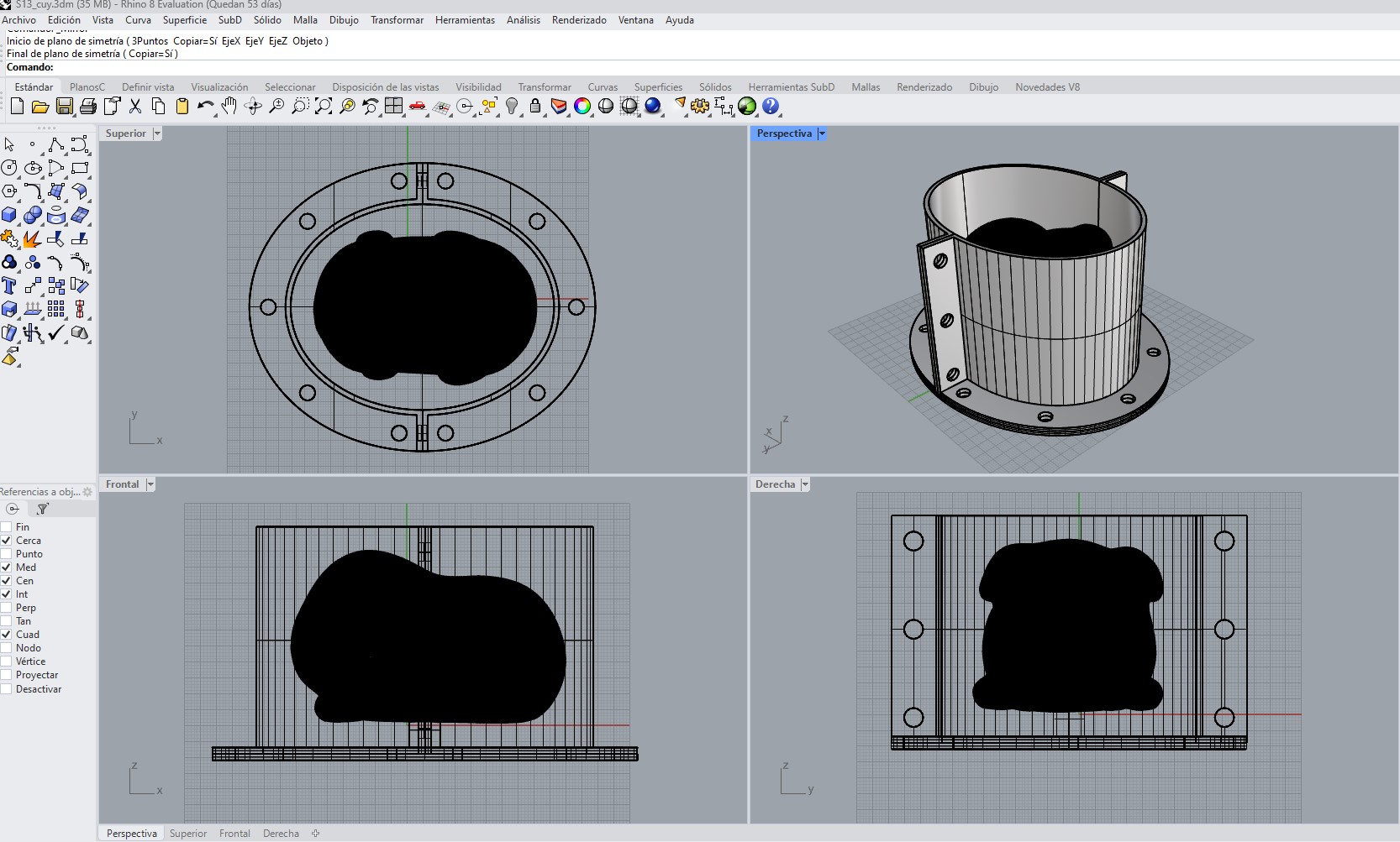
The design consisted of a circular base with holes distributed along the perimeter to allow fastening using bolts, and a vertical cylindrical body that contained the mold volume. At the top, lateral extensions with holes were included, intended to reinforce the fixation system and prevent displacement during the casting process.
The guinea pig was positioned within the volume with an approximate 1 cm distance from the walls, ensuring a sufficient thickness of silicone around the entire piece. The mold walls were defined with a thickness of 2 mm, balancing structural rigidity and material efficiency in 3D printing.
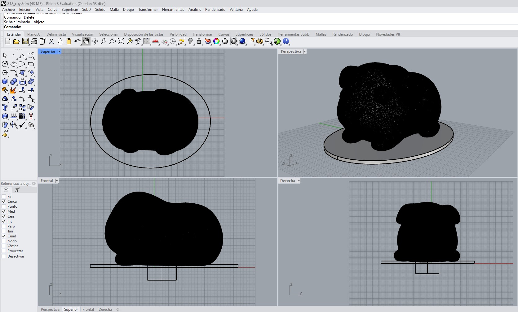
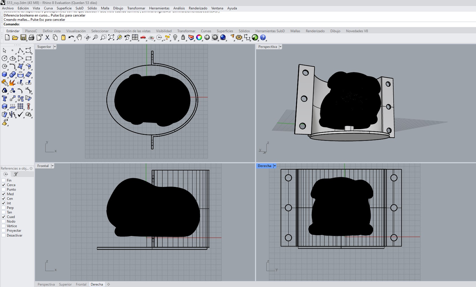
Additionally, a cylindrical hole was incorporated as a holding system, allowing the guinea pig to remain fixed during the silicone pouring process.
However, this approach presented several critical limitations. Since it was a single-piece mold, the extraction of both the original model and the final cast piece depended entirely on the flexibility of the material, which was not sufficient given the geometry of the guinea pig. The shape generated areas of entrapment that made demolding difficult, increasing the risk of deforming the silicone or damaging the piece.
Another issue identified was the lack of control over material flow and air evacuation. Without a defined parting plane or channels, the formation of internal bubbles and voids was more likely.
Overall, this first proposal allowed validation of proportions, wall thickness, and the holding system, but clearly showed that a monolithic mold approach was not suitable for this geometry. This led directly to the development of the second version using a two-part mold, which addressed both demolding and process control issues.
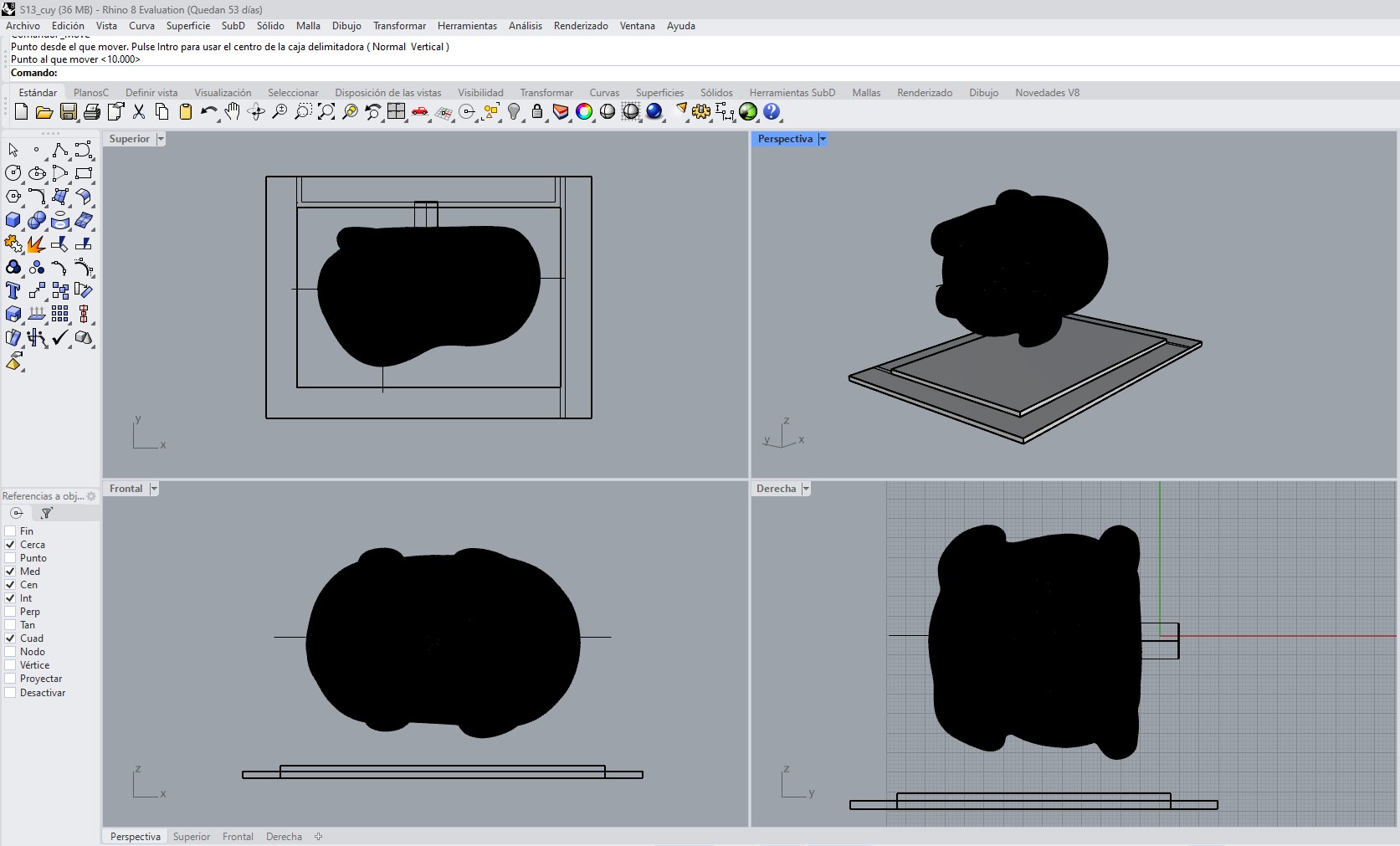
2.2 Second Mold Design Proposal
The second iteration of the mold directly responds to the problems identified in the first version, particularly those related to demolding and process control. Instead of a closed volume, a two-part detachable mold was designed, allowing the system to be opened and the piece to be released without applying excessive stress to the silicone.
The design consists of an open box-like structure made up of flat panels assembled using bolts. This configuration allows each component to be fabricated independently through 3D printing and then assembled in a controlled manner.
The guinea pig is positioned inside the volume, maintaining an approximate 1 cm gap from the walls, ensuring a proper silicone thickness. Unlike the first version, this mold does not fully encapsulate the piece in a single mass but instead creates two clearly defined halves based on a vertical parting plane.
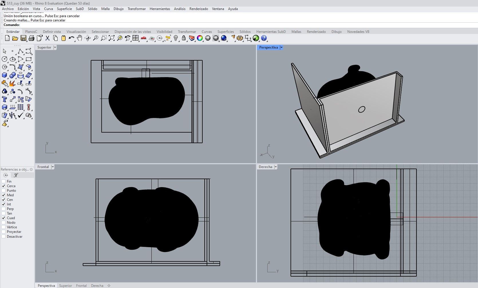
The side panels include evenly distributed 4 mm diameter holes, which allow proper alignment of the mold faces, controlled pressure during closure, and prevention of displacement during casting.
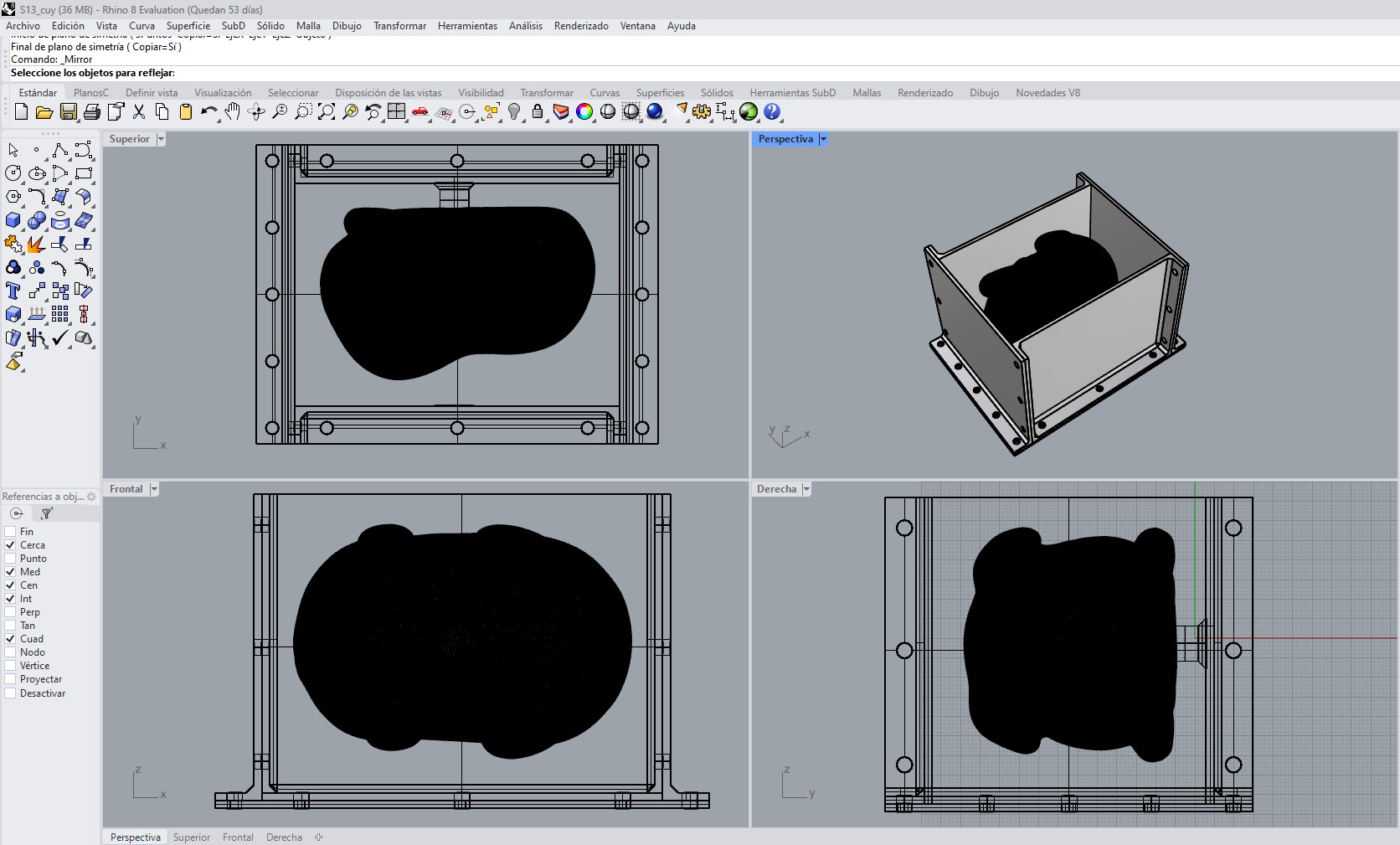
The base also incorporates a perimeter fixation system that stabilizes the entire assembly. This approach turns the mold into a mechanically active structure rather than just a passive container.
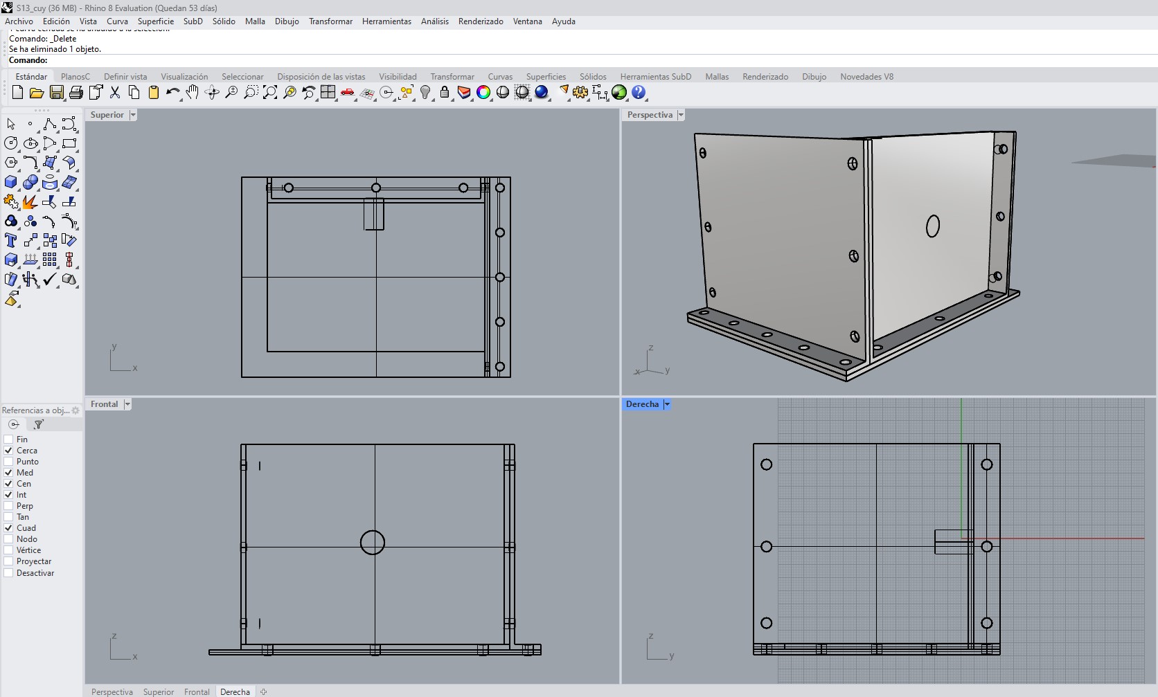
A key aspect of this version is that the design anticipates the entire process: not only how to contain the silicone, but also how to open the mold, separate the parts, and remove the final piece. It also allows the casting process to be performed in two stages, incorporating alignment features to improve registration between both halves.
From a construction standpoint, this solution is also more robust. Since it is composed of flat panels, it reduces deformation caused by FDM printing and simplifies surface post-processing.
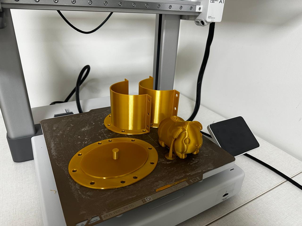
3. Mold Fabrication
Both mold iterations were prepared through a digital fabrication workflow that included slicing and FDM 3D printing. The models were processed using Bambu Studio and fabricated on a Bambu Lab A1 printer using PLA filament.
FDM (Fused Deposition Modeling) is an additive manufacturing process in which thermoplastic material is extruded layer by layer through a heated nozzle. While this technology is accessible and efficient, it introduces a key limitation: the surface texture generated by visible layer lines, which directly affects the quality of the mold and the final cast.
Key Manufacturing Considerations
- A minimum wall thickness of 2 mm was incorporated into the mold design to ensure sufficient structural rigidity during the molding process.
- A 10 mm clearance was maintained between the model and the mold walls to provide adequate silicone thickness and improve mold durability.
- A two-part mold design was developed to facilitate demolding while preserving the geometry of the casted part.
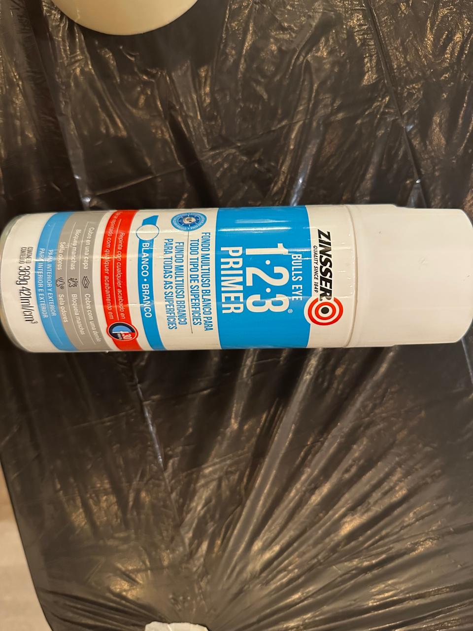
- The master model underwent sanding and primer application before silicone casting to reduce visible layer lines and improve the surface quality of the final mold.
3.1 First Mold Version – Cylindrical Structure
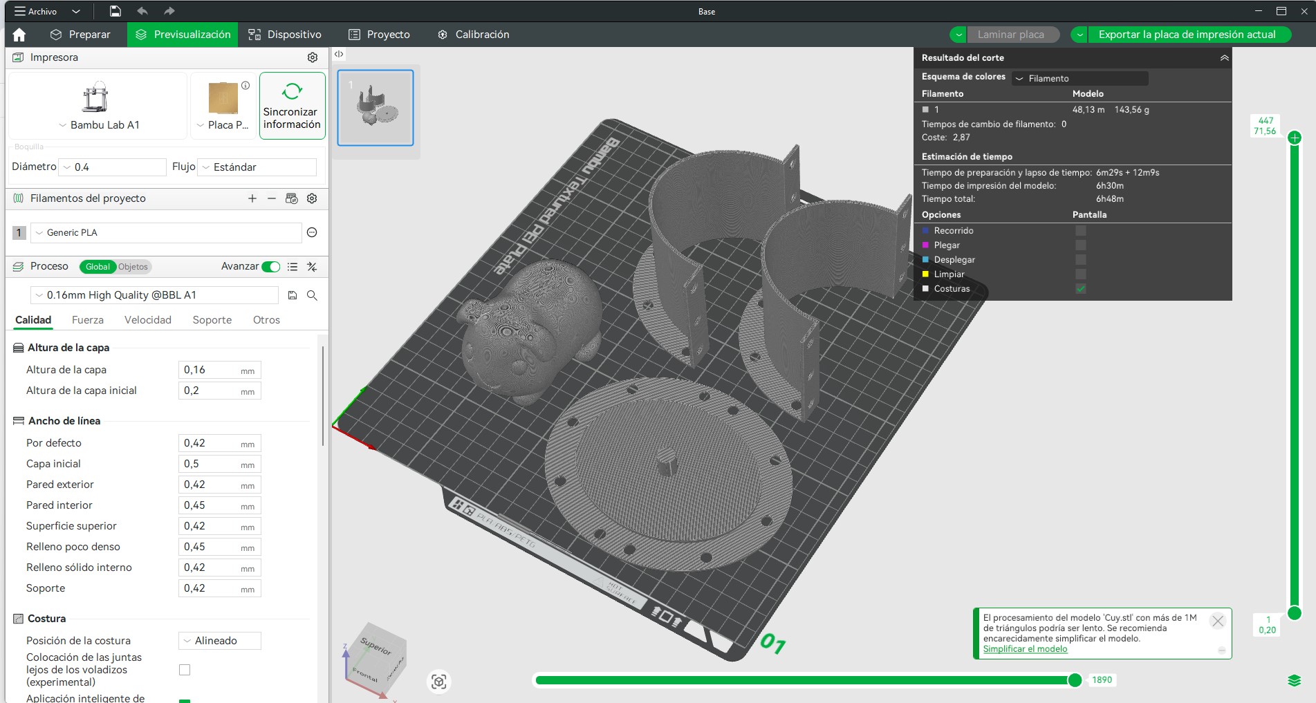
The first mold design, including the cylindrical body, base, and guinea pig model, was sliced using a high-quality profile. The following parameters were defined:
- Layer height: 0.16 mm (High Quality profile)
- Initial layer height: 0.20 mm
- Nozzle diameter: 0.4 mm
- Line width: ~0.42 mm
- Material: Generic PLA
- Supports: Not heavily required for main geometry
This configuration prioritizes surface quality over speed, which is critical for mold fabrication. The finer layer height reduces the visibility of layer lines, especially on curved surfaces such as the guinea pig geometry.
According to the slicing preview, the total material usage was approximately 143.56 g of filament, with an estimated printing time of around 6 hours and 48 minutes. This reflects the complexity of the geometry, particularly due to the organic shape of the model.
A warning was identified during slicing indicating a high polygon count in the mesh (more than 1 million triangles), which may slow down processing. This is typical when working with meshes generated from AI-based tools such as Hi3D.
3.2 Second Mold Version – Two-Part Modular System
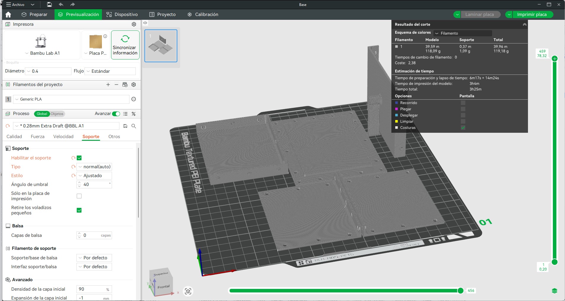
The second iteration of the mold, composed of flat panels and structural components, was sliced using a faster configuration, as surface curvature was less critical in this case.
- Layer height: 0.28 mm (Extra Draft profile)
- Nozzle diameter: 0.4 mm
- Material: Generic PLA
- Supports: Enabled (automatic)
- Support threshold angle: 40°
The use of a larger layer height significantly reduced printing time while maintaining sufficient dimensional accuracy for planar components. Since these parts do not directly define the surface finish of the cast object, a lower resolution was acceptable.
Supports were enabled to stabilize vertical elements and overhangs, ensuring correct geometry during printing. The threshold angle of 40° allowed automatic detection of areas requiring support while minimizing unnecessary material usage.
The total material usage for this version was approximately 119.18 g, with an estimated printing time of around 3 hours and 25 minutes. This represents a more efficient fabrication process due to the simplified geometry and optimized slicing strategy.
4. Post-processing
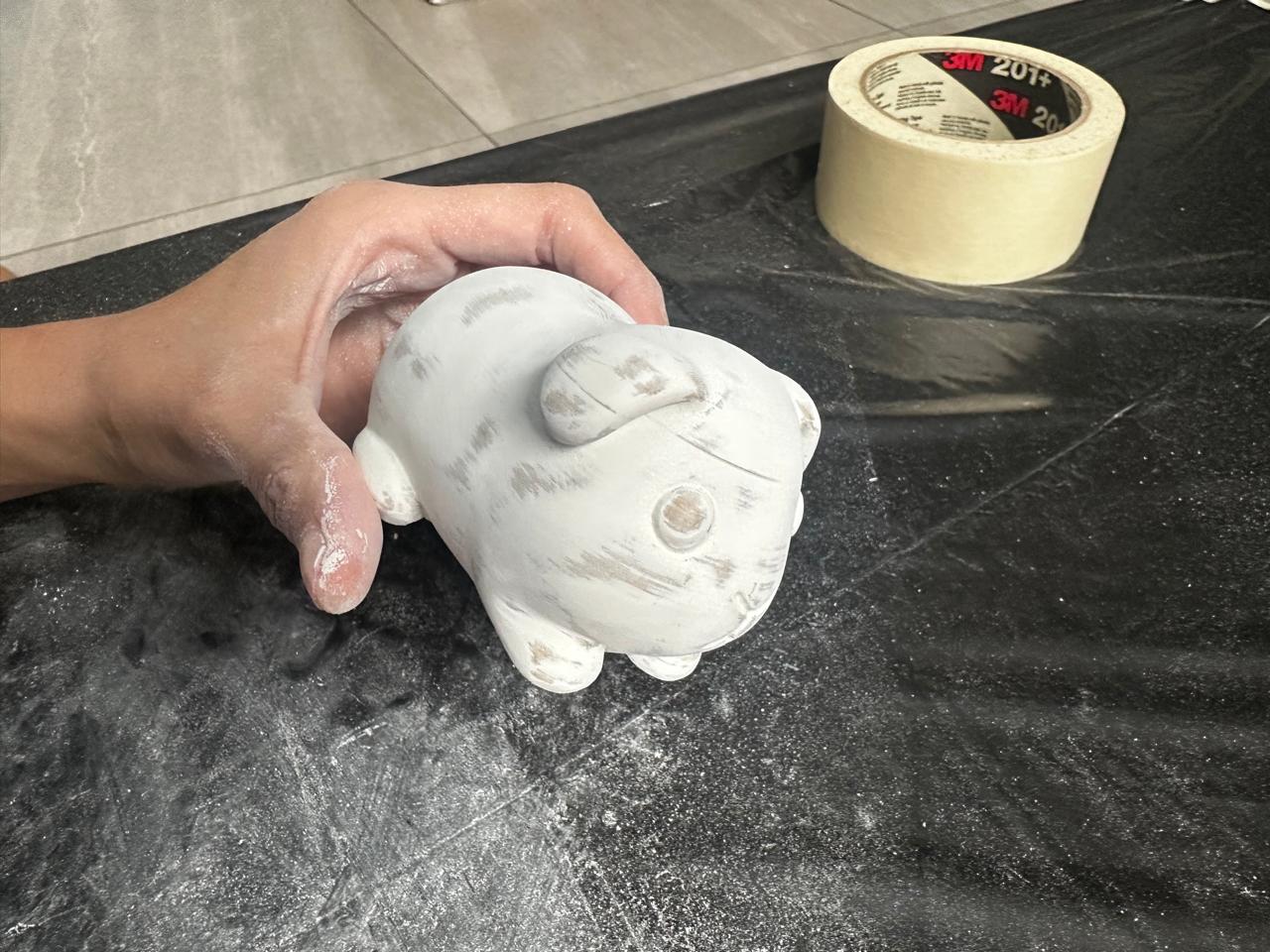
Due to the nature of FDM printing, post-processing was a critical step to improve the surface quality of the mold. The layer-by-layer fabrication process generates visible ridges that directly transfer to the silicone mold and, consequently, to the final cast piece. For this reason, a surface refinement workflow was applied to both mold iterations.
The process began with the removal of supports and general cleaning of the printed parts. Special care was taken when removing support structures to avoid damaging edges or altering dimensional accuracy, particularly in areas that would define the mold cavity.
After cleaning, a first layer of binder was applied. This coating acts as a sealant, reducing surface porosity and improving the adhesion of subsequent finishing processes. It also helps to partially fill micro-gaps between layers, creating a more uniform surface.
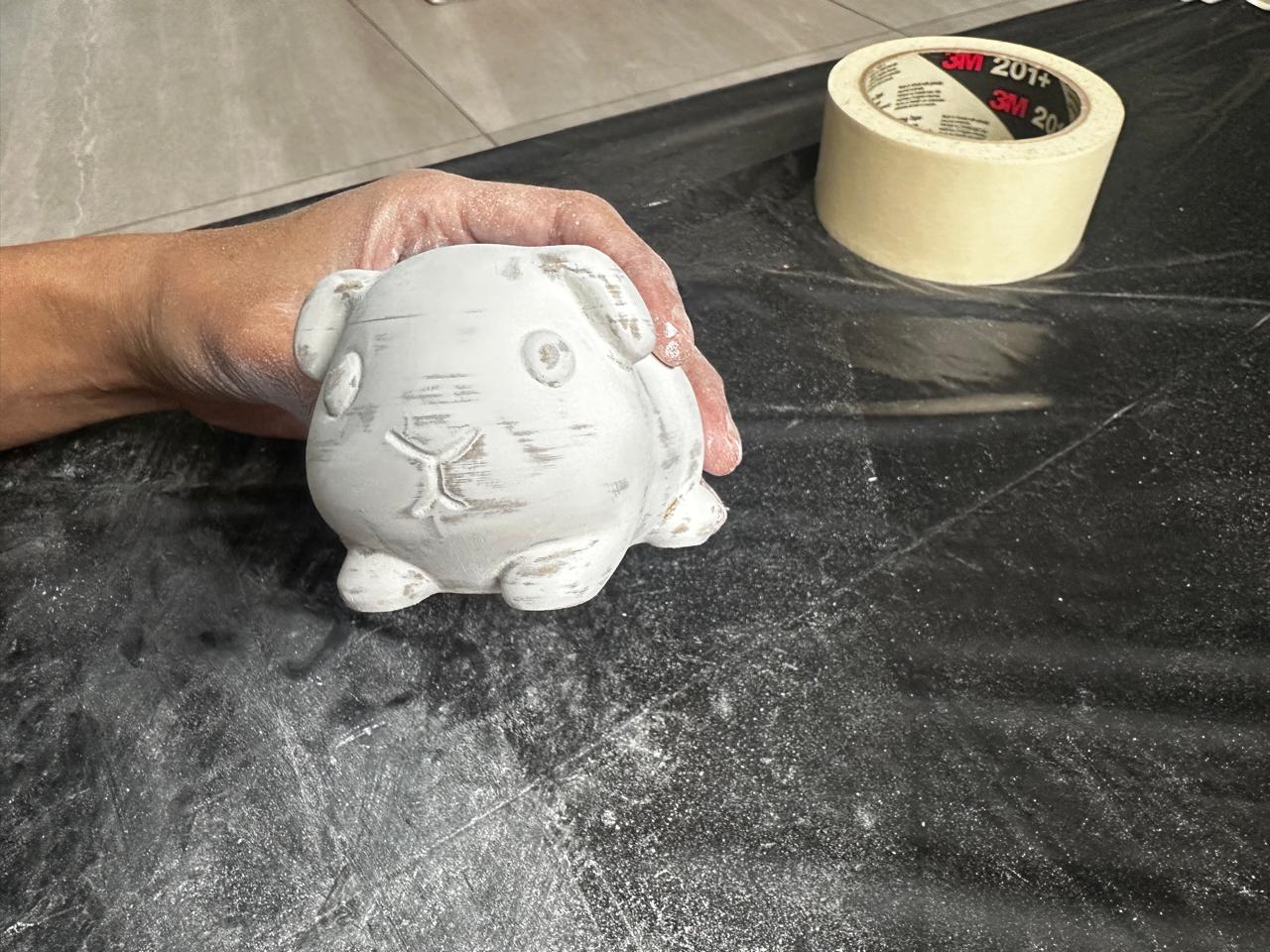
Once the binder was dry, a progressive wet sanding process was carried out. Sanding started with 360 grit sandpaper to remove the most prominent layer lines. This stage focuses on leveling the surface rather than achieving a smooth finish.
After the initial leveling, sanding continued with finer grits, gradually reaching 1000 grit. This step refines the surface and reduces visible scratches left by the coarser sandpaper, resulting in a smoother and more continuous finish.
A second layer of binder was then applied to further seal the surface and improve uniformity. This was followed by a final fine sanding stage, focusing on achieving a consistent texture across all contact surfaces of the mold.
The objective of this process was to minimize the transfer of FDM layer lines to the silicone mold. Since the mold captures all surface details, even minor imperfections in the printed part would be replicated in the final cast.
Through this post-processing workflow, a significantly improved surface quality was achieved, ensuring better mold performance, easier demolding, and a cleaner final piece.
5. Safety Considerations
Before starting the molding and casting process, the Safety Data Sheets (SDS) of all materials were reviewed to identify potential hazards, required personal protective equipment (PPE), and safe handling procedures. Appropriate safety measures were followed throughout the fabrication process.
| Material | Application | Main Hazards | PPE Required | Safety Measures |
|---|---|---|---|---|
| RTV Silicone Rubber | Mold fabrication | May cause mild skin and eye irritation before curing. | Gloves, safety glasses | Work in a ventilated area and avoid direct skin contact. |
| Eco Resin Powder | Casting material | Dust may irritate the respiratory system and eyes. | Dust mask, gloves | Avoid inhalation of dust and clean spills immediately. |
| Eco Resin Liquid | Binding component for casting | May cause skin and eye irritation. | Gloves, safety glasses | Avoid prolonged contact and wash hands after use. |
Throughout the process, gloves were used when handling uncured materials, and the work area was kept clean and ventilated. Special attention was given to avoiding direct contact with liquid components and minimizing exposure to airborne dust generated during material preparation.
6. Material preparation for Molding
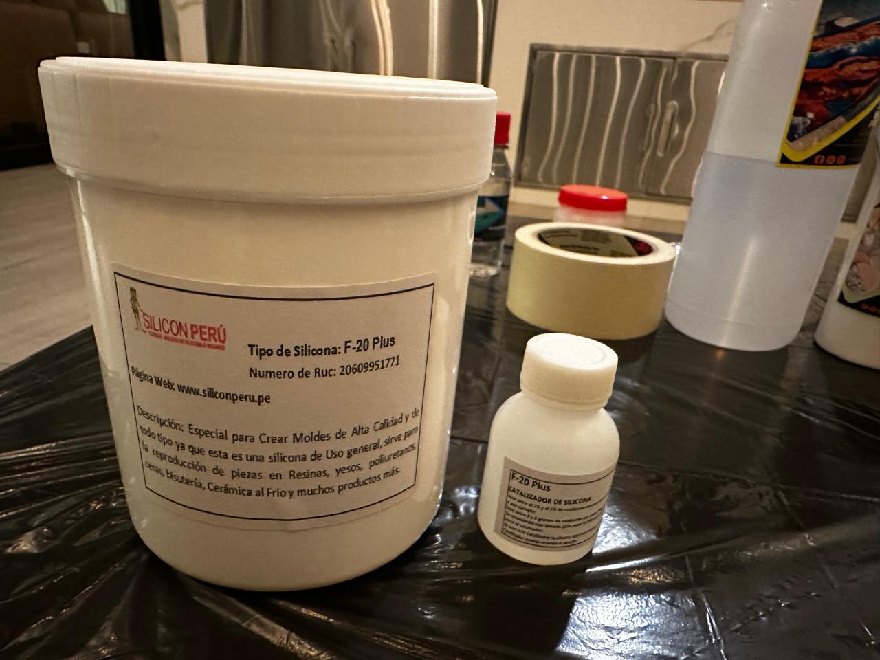
Before casting, both the physical system and the materials were carefully prepared. The mold making process was carried out using RTV silicone F-20 Plus from Silicon Perú, a general-purpose silicone suitable for reproducing parts in materials such as resins, plaster, and cold ceramics. This material offers a balance between flexibility and mechanical resistance, allowing for safe demolding without damaging the mold.
The silicone was mixed with its corresponding catalyst at a proportion of approximately 3% by weight, ensuring proper curing of the material. Maintaining this ratio was critical to avoid incomplete curing or excessive rigidity in the final mold.
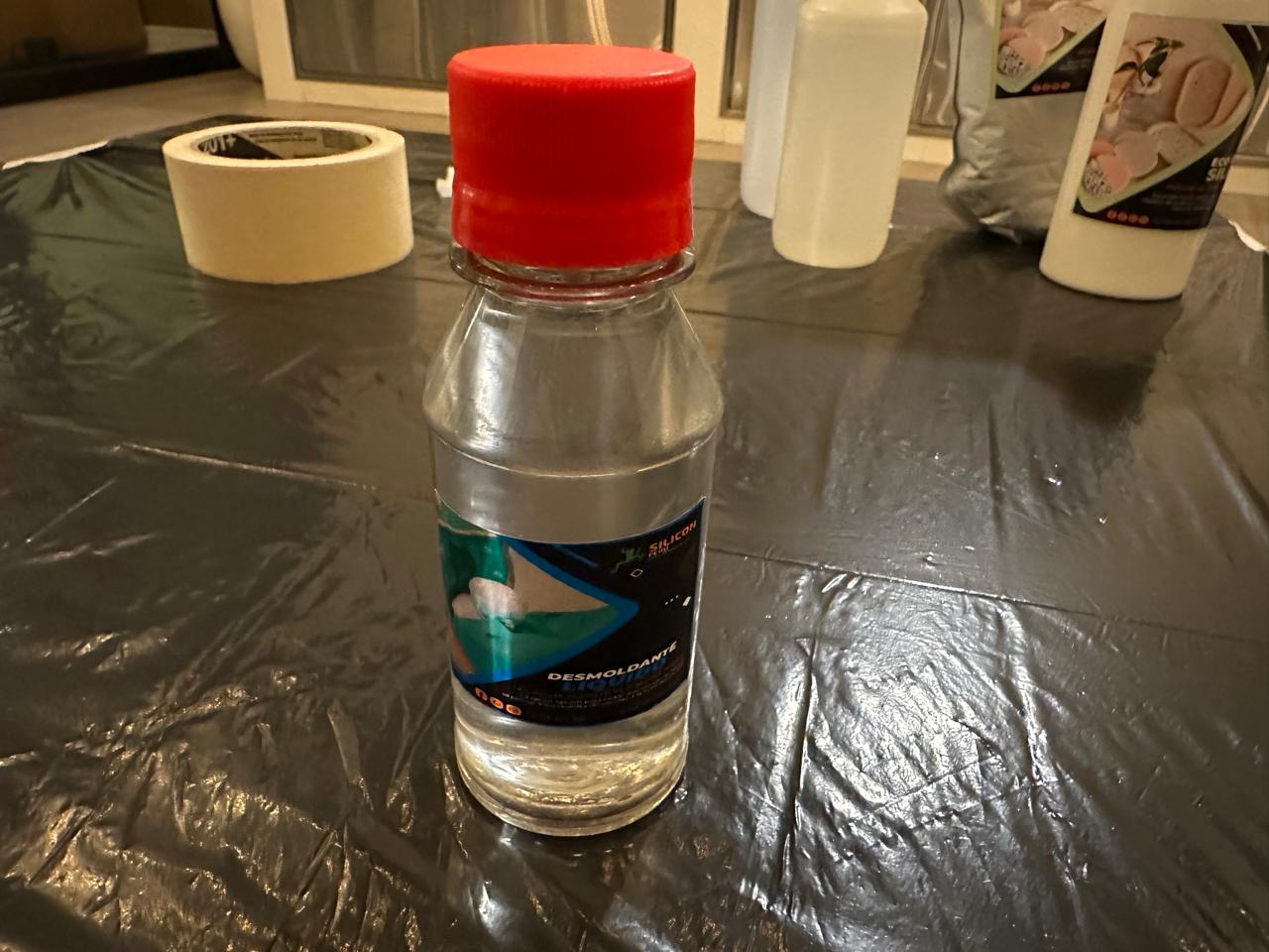
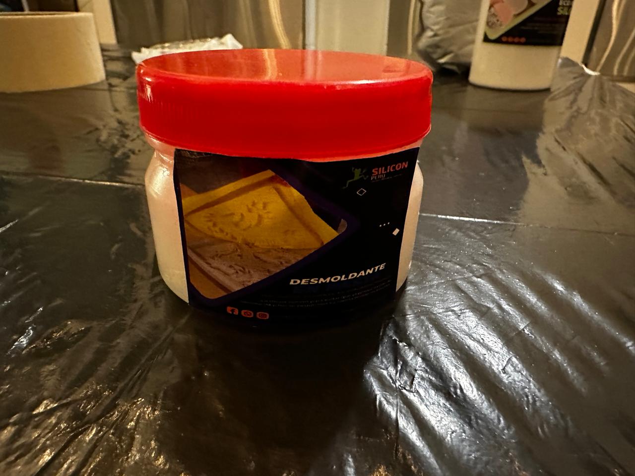
To ensure proper separation during the process, two types of release agents from Silicon Perú were used:
- Liquid release agent:applied to the internal surfaces of the rigid 3D printed mold to prevent adhesion between the silicone and the PLA parts.
- Paste release agent: applied between the two silicone halves after curing the first part, preventing both sides from bonding during the second casting stage.
Additional materials included mixing containers and manual tools for stirring the silicone, as well as masking tape used to seal the mold during the casting process.
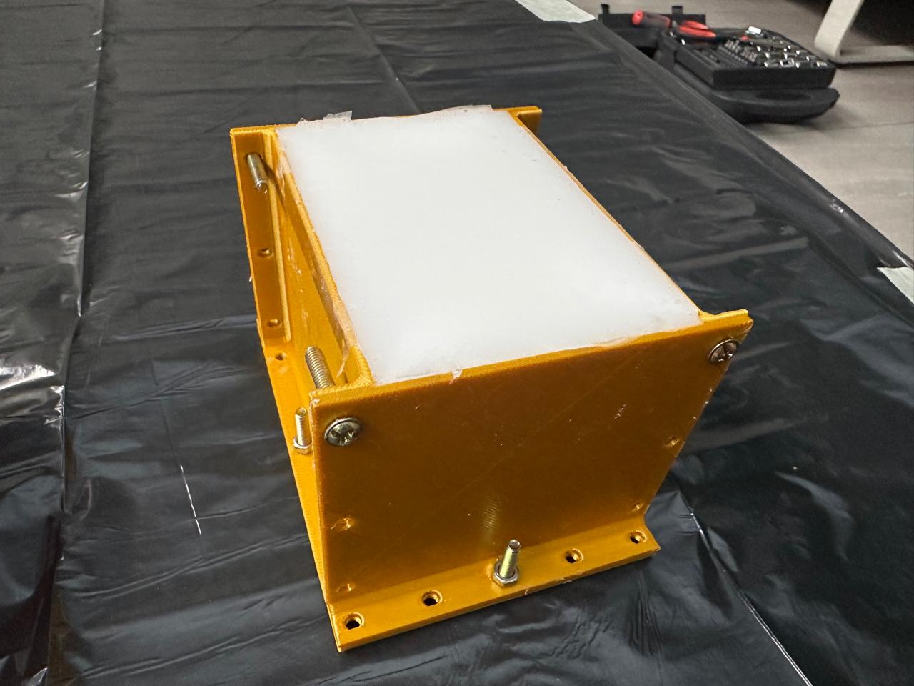
7. Mold Assembly and Preparation
Before casting the silicone, the mold required a precise assembly and sealing process to ensure correct alignment, prevent material leakage, and maintain dimensional accuracy during curing.
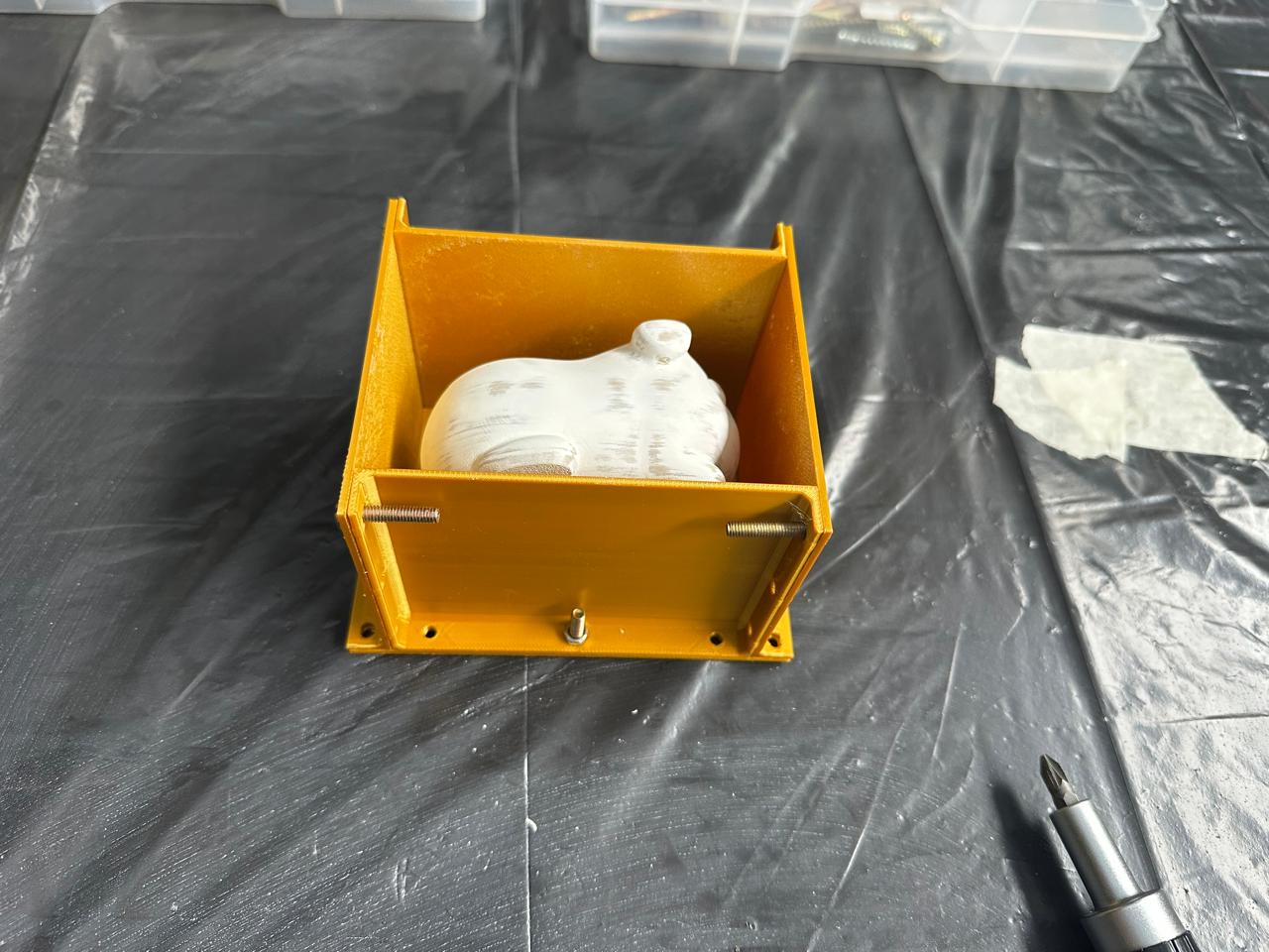
The mold was composed of multiple 3D printed parts, including a base and vertical panels. These components were assembled using bolts inserted through pre-designed 4 mm diameter holes. This fastening system ensured proper alignment between all elements and allowed controlled pressure to be applied when closing the mold.
During assembly, special attention was given to the alignment of the walls relative to the base. Any misalignment at this stage could result in deformation of the mold cavity or inconsistencies in the final cast piece.
Once assembled, the internal joints between panels were inspected to identify potential gaps. Since FDM parts are not perfectly airtight, masking tape was applied along critical internal seams to prevent silicone leakage during pouring. This step was essential to maintain the integrity of the mold and avoid material loss.
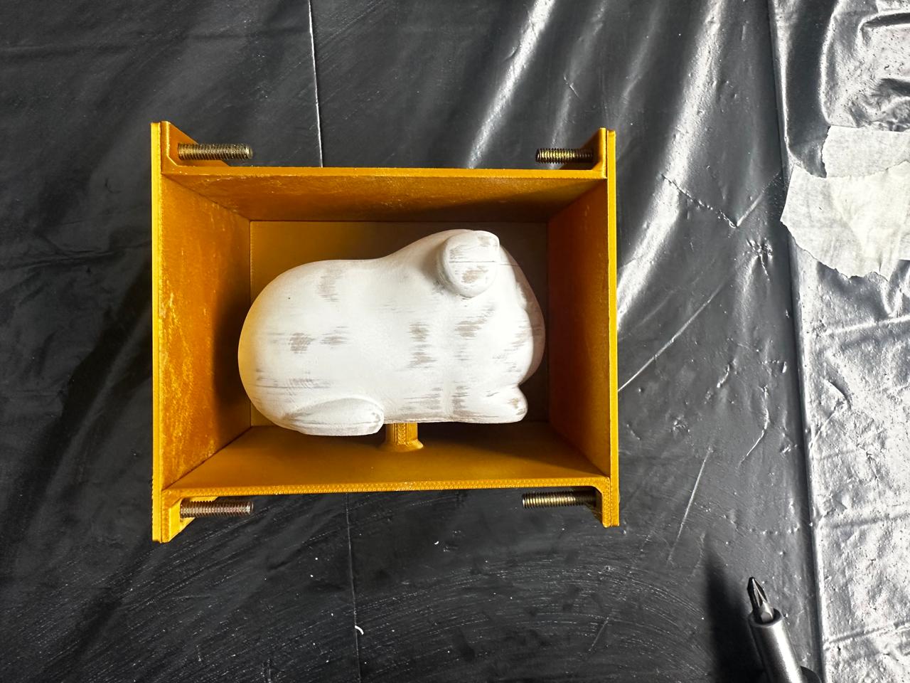
The guinea pig model was positioned inside the mold using the previously designed cylindrical support feature. This ensured that the piece remained fixed in place during casting and maintained a consistent gap of approximately 1 cm between the model and the mold walls.
After positioning the model, the entire internal surface of the mold was prepared by applying a liquid release agent. This was done carefully to ensure full coverage, especially in corners and contact areas, reducing the risk of the silicone adhering to the rigid mold.
The final assembled mold was then checked for structural stability, proper sealing, and correct positioning of all elements before proceeding to the silicone mixing and pouring stage.
8. Silicone Mixing and Casting
The silicone was prepared using a ratio of 3% catalyst per 100 grams of base material. For each half of the mold, approximately 400 g of silicone and 12 g of catalyst were used. The mixture was prepared manually, ensuring proper homogenization to avoid areas that might not cure correctly.
The casting process was carried out in two stages. First, silicone was poured into one half of the mold. At this stage, alignment elements were added to ensure proper registration between both halves. During pouring, attempts were made to reduce bubble formation by gently tapping the mold against the table and manually manipulating the material, although this method has clear limitations.
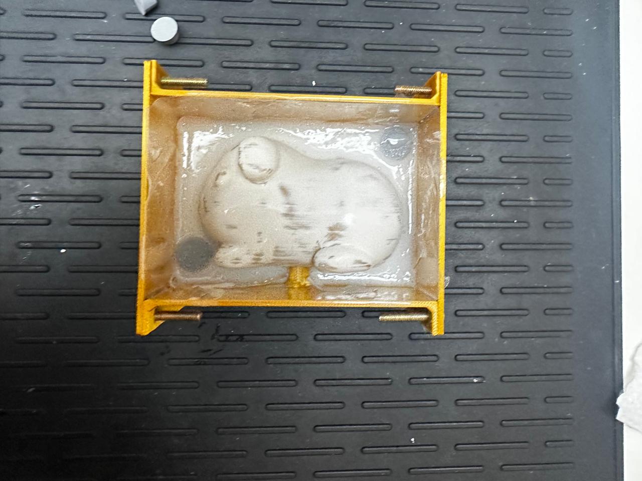
Once the first half had cured, the alignment elements were removed and a paste release agent was applied to the exposed surface. This step is critical, as without it, both silicone halves would bond together and the mold would become unusable. Then, the second half was poured, completing the mold.
9. Demolding and Mold Evaluation
After the curing time, the bolts were removed and both halves of the mold were separated. The opening was achieved without major damage, confirming that the decision to use a two-part mold was appropriate.
The quality of the result was evaluated by observing cavity definition, alignment between halves, and overall structural integrity. The geometry was reproduced correctly, although internal bubbles and minor surface imperfections were identified.
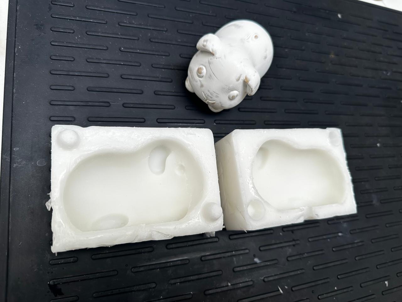
These defects are directly related to the manual mixing and pouring process, which introduces air into the material. As a future improvement, more controlled degassing or pouring techniques should be considered.
10. Final Casting and Post-Processing
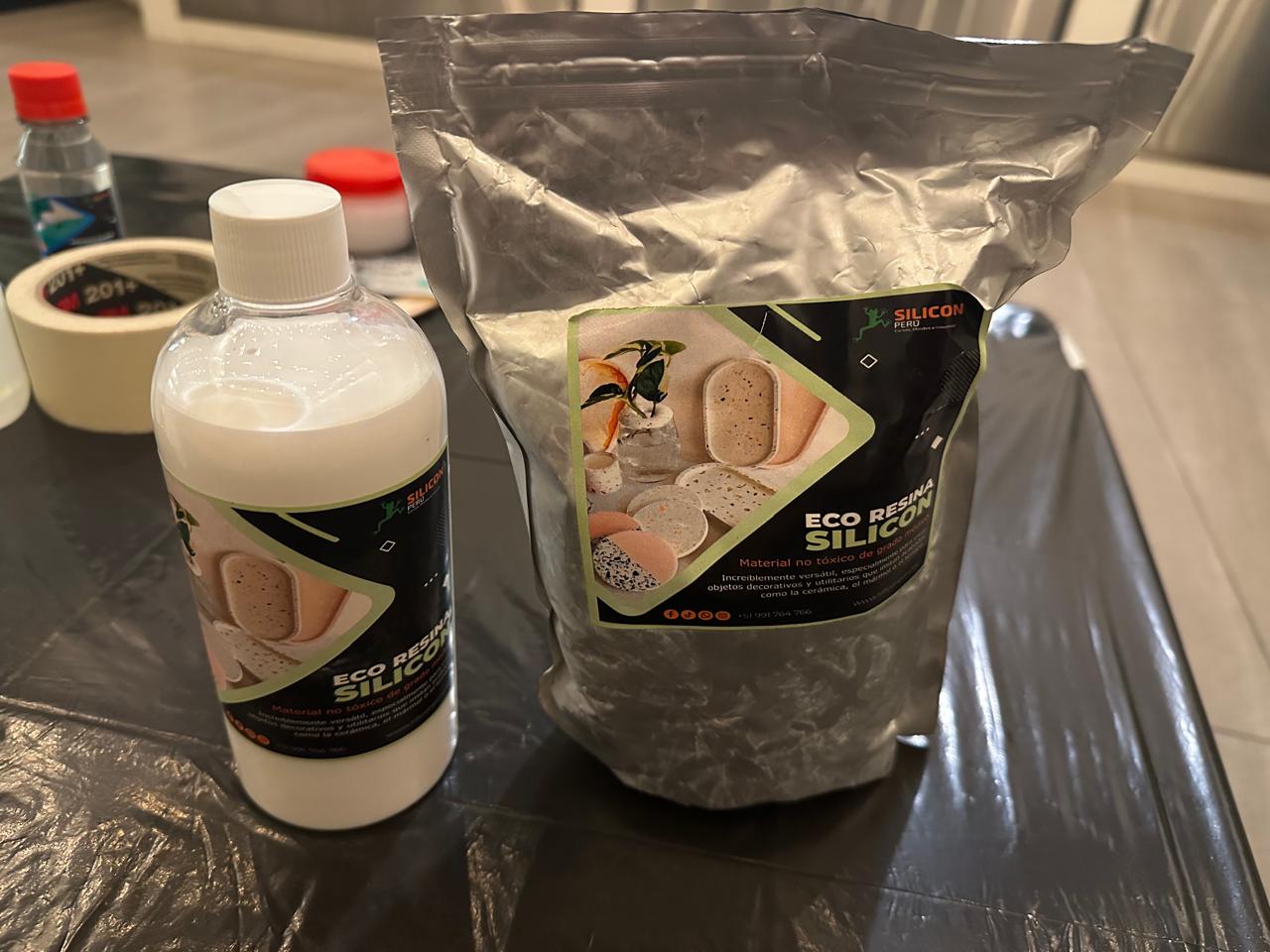
Once the silicone mold was validated, the final piece was produced using Eco Resin Silicon from Silicon Perú, a non-toxic casting material commonly used for decorative objects and functional prototypes with a ceramic-like finish.
This material is composed of two components: a mineral-based powder and a liquid binder. When mixed, it produces a fluid paste that can be cast into molds and cures into a rigid solid with a matte surface.
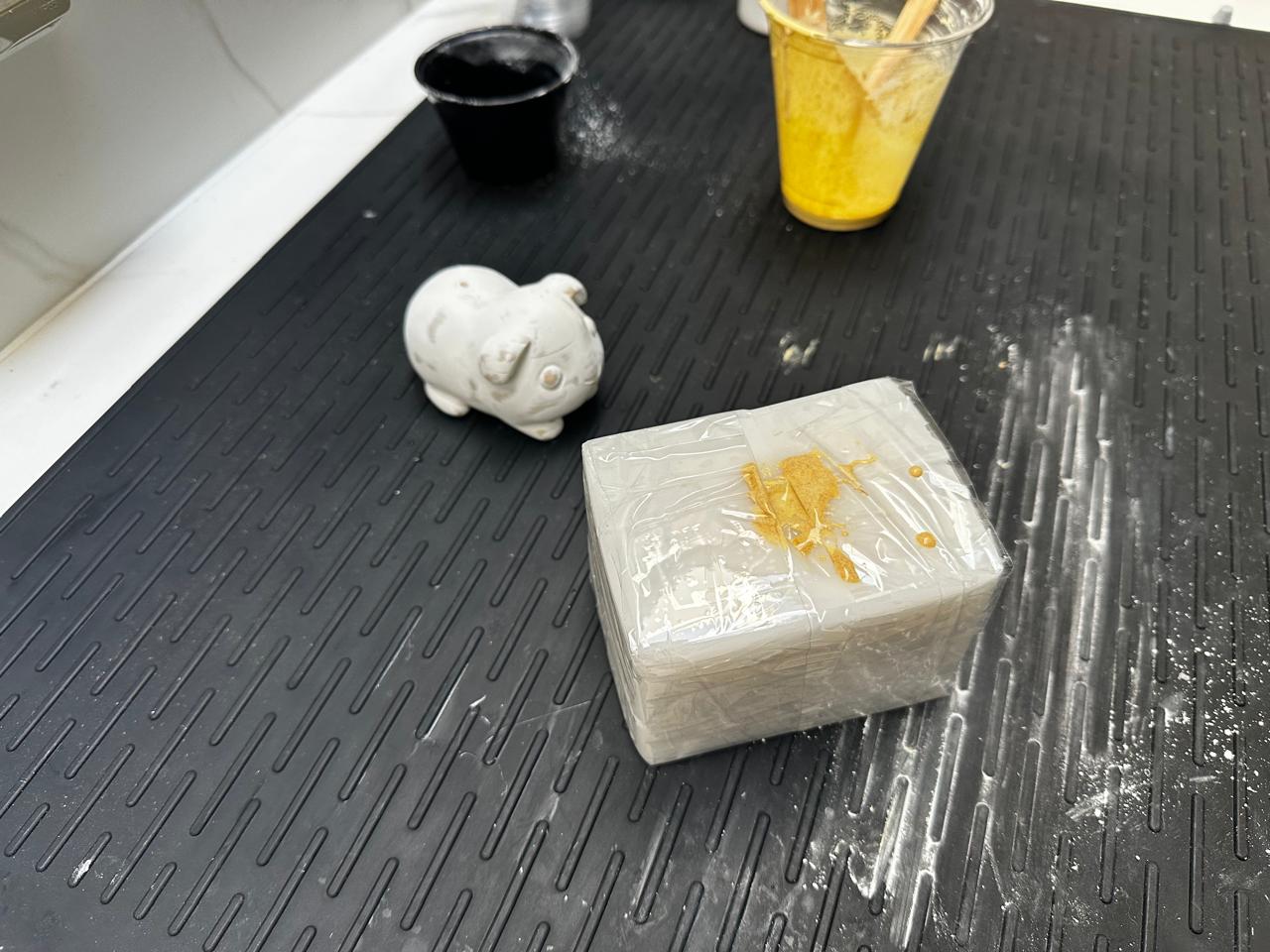
First, the required material volume was estimated by filling the mold cavity with water. This allowed for an approximate calculation of the mixture needed, avoiding material waste or shortages during casting. The mold was then completely dried and sealed using adhesive tape to prevent leaks.
The resin mixture was prepared following a ratio of 3 parts powder to 1 part liquid. In this case, approximately 1.5 cups of powder and 0.5 cups of liquid were used, achieving a suitable consistency for pouring.
To introduce color, two teaspoons of turmeric were added as a natural pigment. This provided a uniform coloration while maintaining the material’s workability.
The mixture was manually stirred until a homogeneous texture was achieved, trying to minimize air incorporation. Due to the viscosity of the mixture, care was taken to break up any lumps and ensure even distribution of the liquid binder throughout the powder.
The material was then poured slowly and continuously into the mold cavity. During this process, the mold was gently tapped against the table to help release trapped air bubbles and allow the material to flow properly into all details.
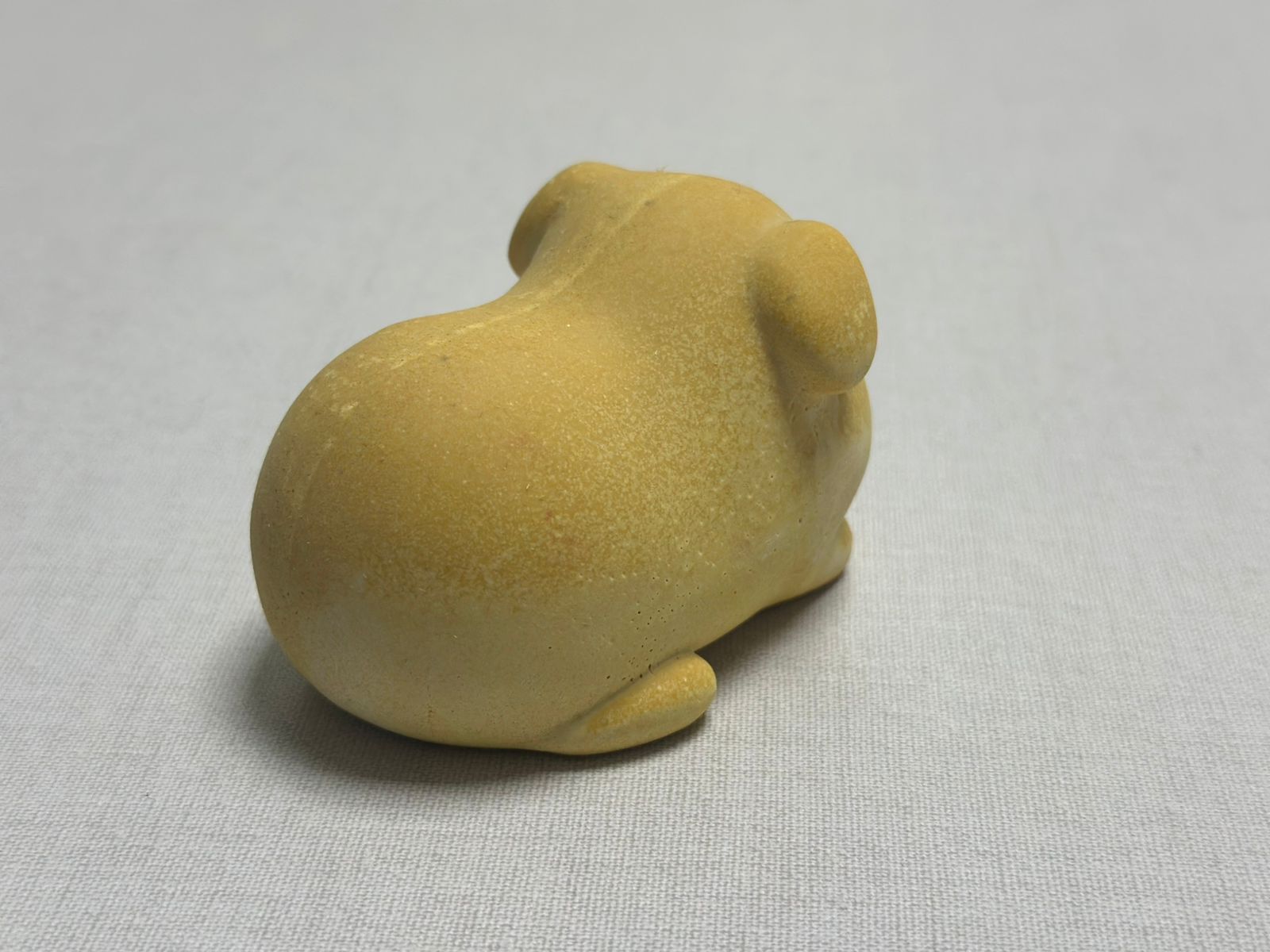
Once the mold was completely filled, the material was left to cure at room temperature according to the recommended time. The curing process resulted in a rigid solid with a smooth, matte finish, suitable for further post-processing.
10. Demolding and Final Piece Post-Processing
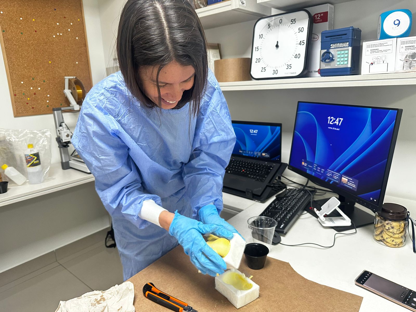
After the eco-resin had fully cured, the demolding process was carried out. First, the fastening elements and adhesive tape used to seal the mold were removed. Then, both halves of the silicone mold were carefully separated, applying gradual and controlled force to avoid deformation or tearing of the material.
The flexibility of the silicone facilitated the opening process, allowing the piece to be released without damage. It is important at this stage not to apply force at a single point, but to open the mold evenly to prevent localized stress.
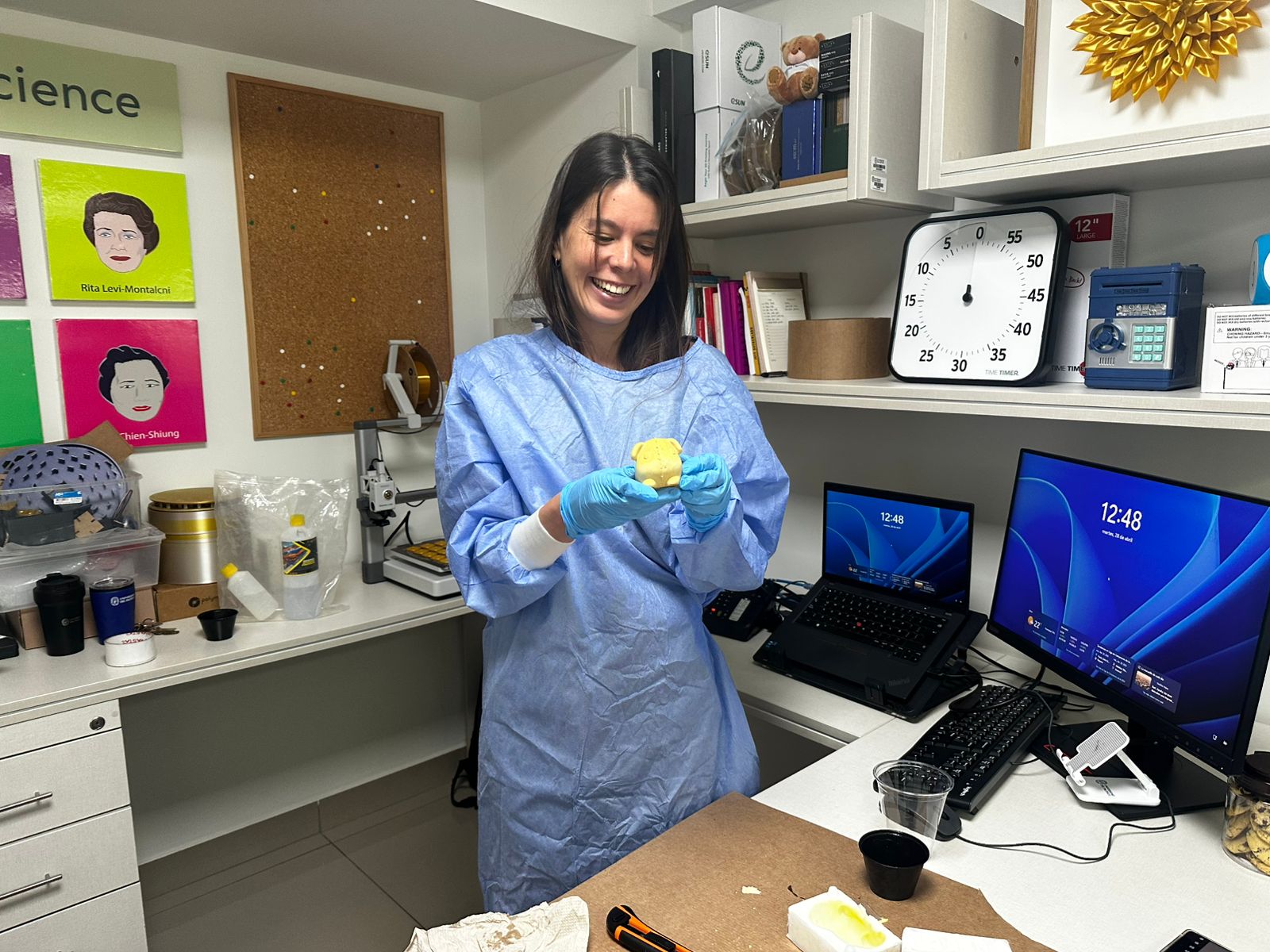
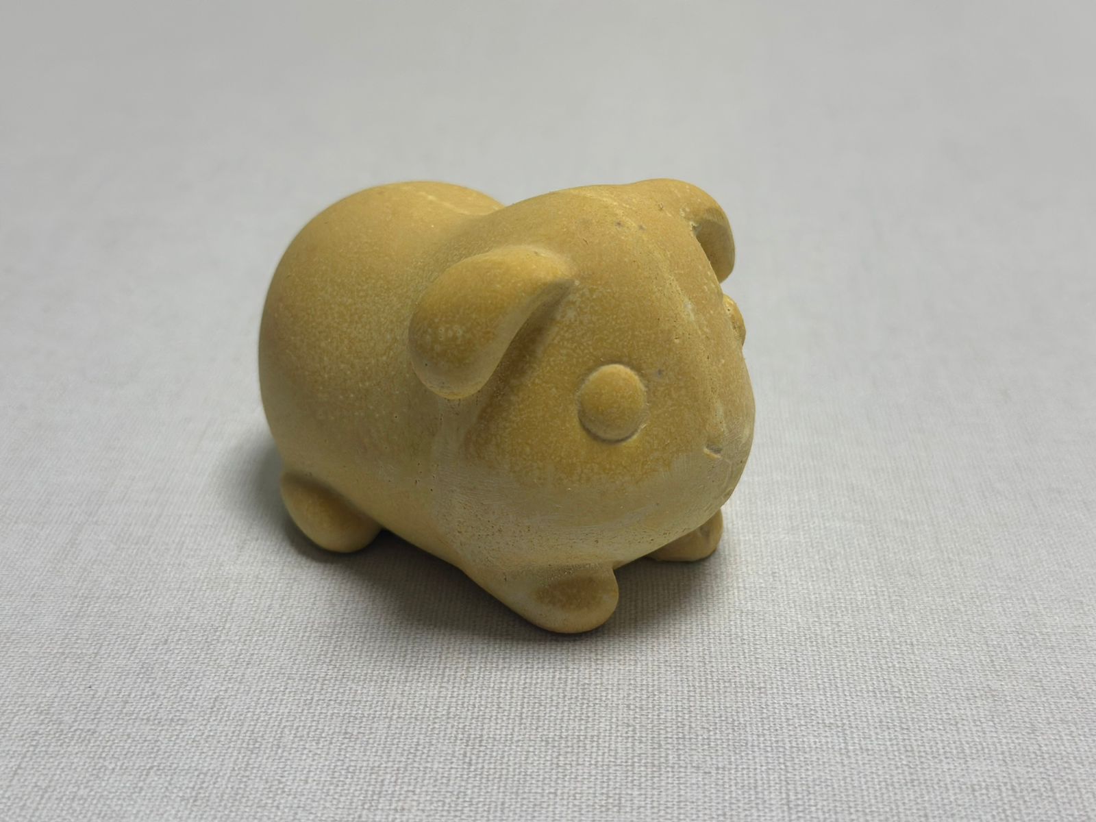
Once removed, the piece was visually inspected. Flash along the parting line and minor surface imperfections were identified as a result of the casting process.
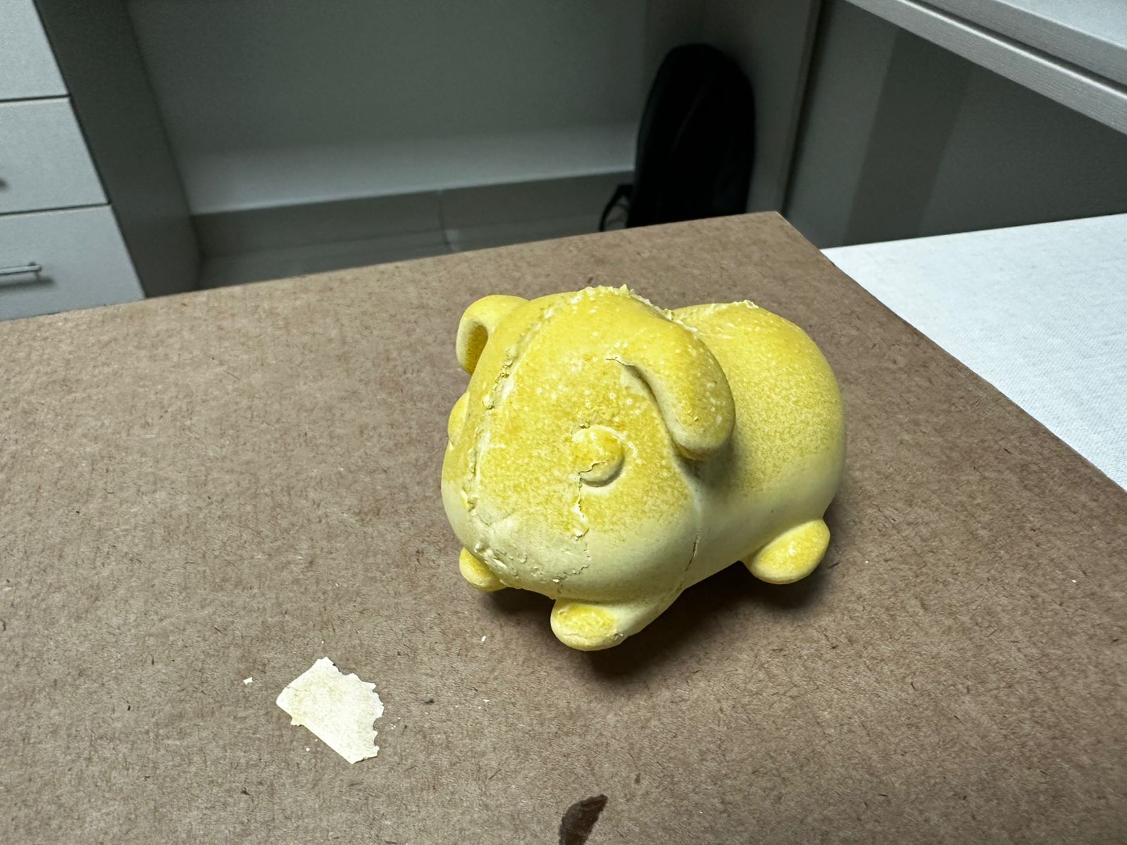
As part of the final post-processing, a cutter was used to carefully remove the flash, following the mold’s parting line. This was done with controlled cuts to avoid damaging the main geometry. In more delicate areas, the cutting angle and pressure were adjusted to achieve a cleaner finish.
This final step improved both the visual and tactile quality of the piece, removing process-related defects and resulting in a cleaner and more defined final object.
Lessons Learned
Designing the mold with demolding in mind is critical. The first single-piece design failed due to geometry constraints, while the two-part mold enabled proper extraction.
Surface quality from FDM printing directly affects the final result. Post-processing (binder + sanding) is essential to reduce layer lines and improve mold performance.
Proper mold assembly and sealing are key. Small gaps can cause leakage, and misalignment affects the accuracy of the final piece.
Air bubbles were a consistent issue due to manual mixing and pouring. Simple techniques like tapping help, but are limited without proper degassing.
Correct use of release agents is essential to prevent unwanted bonding and ensure successful separation between mold parts.
Conclusions
The project successfully demonstrated a complete workflow combining CAD design, FDM fabrication, and casting techniques to produce a functional mold and final piece.
Iteration was key to success. Moving from a single-piece mold to a two-part system solved major issues related to demolding and process control.
While digital fabrication enables fast production, post-processing and material handling are critical to achieving good results.
Some limitations such as air bubbles and surface imperfections remain, and could be improved with better casting techniques in future iterations.