
Week 11 | Networking and Communications
Group Assignment
This week's group assignment consisted of establishing communication between two different projects by sending a message from one device to another using networking or communication protocols. The objective was to understand how devices can exchange information, how communication protocols work, and how networking enables distributed systems and interactive projects.
During this assignment, we tested communication between two boards, sending and receiving data to verify that the connection was working correctly. This allowed us to understand the basics of serial communication, data transmission, and device synchronization.
The complete documentation of the group work can be found in the following page:
Group assignment documentation
Individual Assignment
This week I worked on embedded networking and communications by implementing wireless communication between a smartphone and a XIAO ESP32-C3 using Bluetooth Low Energy (BLE). The goal was to create a system that could receive commands from a mobile device and control actuators remotely.
This assignment also helped me integrate previous work from earlier weeks, including input devices, output devices, and embedded programming. In this case, I connected a PIR sensor, a switch, an LED, and a servo motor to the XIAO ESP32-C3, and then added wireless communication through BLE.
1. Electronic Board
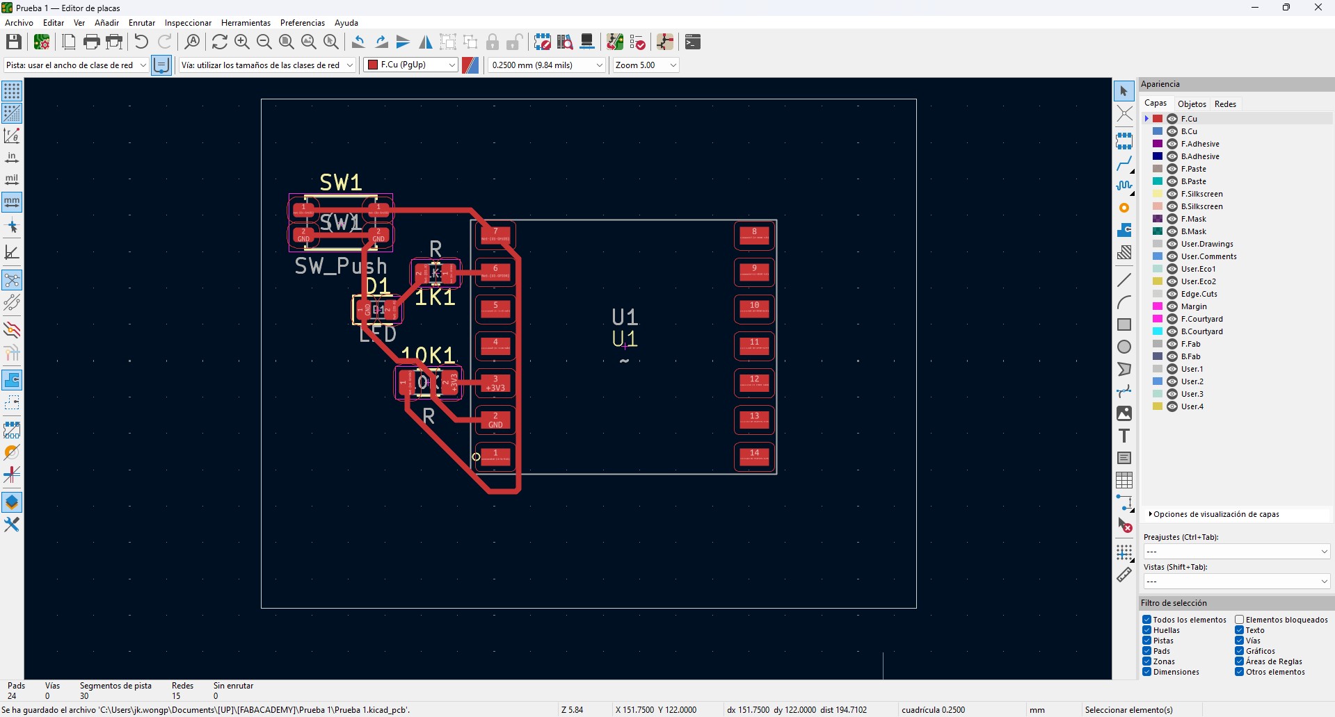
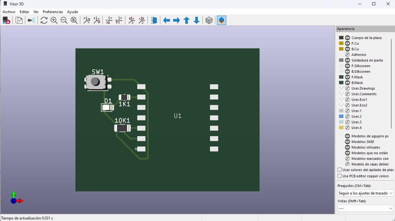
In this week, I continued using the same custom electronic board as the base of the system. The board was designed in KiCad, starting from the electronic schematic and then transitioning into the PCB layout.
The design is centered around a XIAO ESP32 microcontroller, selected for its small size and its processing and communication capabilities. Power distribution through VBUS and GND was clearly organized in order to support multiple devices and future integrations.
The board includes:
- 1kΩ resistors for current limiting in outputs
- 10kΩ resistors used as pull-down or pull-up resistors in inputs
- Header connectors for sensors and actuators
- Accessible pads for easier testing and measurements
The routing was developed on a single side, optimizing paths and avoiding trace intersections, which is especially useful for CNC milling. A 0.4 mm trace width and appropriate spacing were considered to obtain a clean and reliable board.
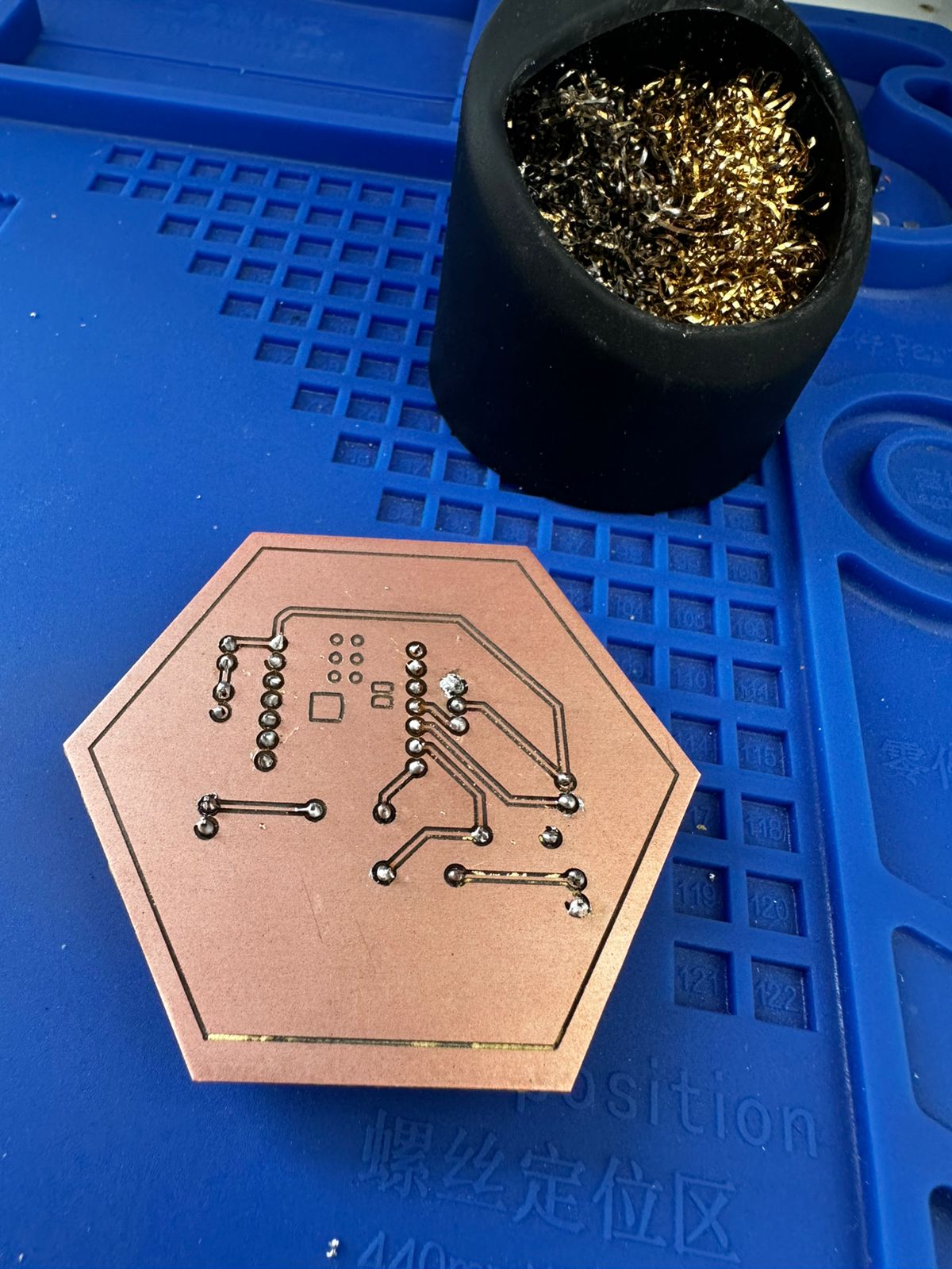
The fabrication process involved milling the PCB from a copper-clad board, followed by manual drilling and THT soldering. Once assembled, continuity was verified with a multimeter and the board was tested to confirm its basic functionality.
Using this platform, I explored communication capabilities through the XIAO ESP32 microcontroller. Because the board had already been designed with accessible pins and a clear power distribution, it was possible to use it as a communication node without modifying the physical PCB.
2. Circuit Diagram
The following diagram shows the connections between the XIAO ESP32C3 microcontroller, the input devices (PIR sensor and switch), and the output devices (servo motor and LED) used in the system.
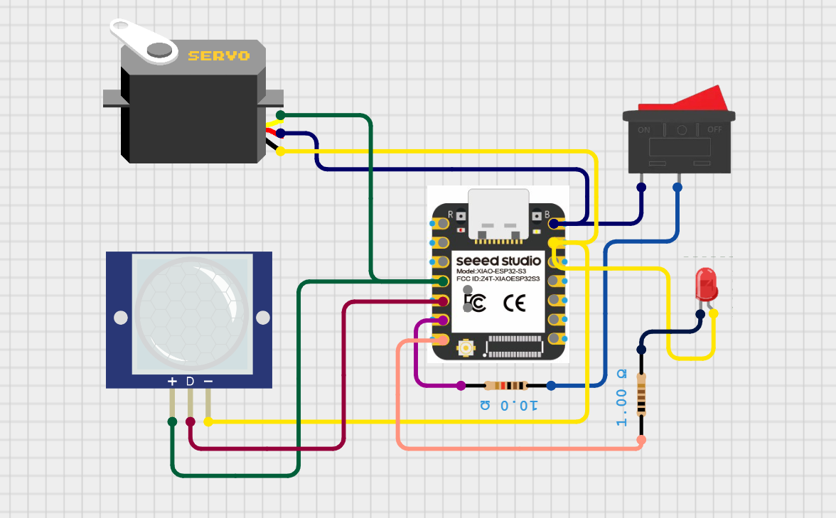
Circuit diagram showing the integration of input devices (PIR sensor and switch) and output devices (servo motor and LED) connected to the microcontroller.
The PIR sensor is connected to a digital input pin and provides a HIGH (1) signal when motion is detected and a LOW (0) signal when no motion is present. The switch is also connected to a digital input pin and acts as a manual control to enable or disable the system.
The servo motor is connected to a PWM-capable output pin of the microcontroller, allowing precise control of its angular position through pulse-width modulation signals. This enables controlled mechanical movement based on the system logic.
The LED is connected to a digital output pin through a current-limiting resistor and acts as a visual indicator of the system state, turning ON or OFF depending on the signal sent by the microcontroller.
This configuration demonstrates how multiple inputs can be processed to control different types of outputs, enabling the system to respond to environmental changes and user interaction through both visual and mechanical feedback.
3. System Description
The system was designed to work in two different modes:
- Automatic mode: the PIR sensor detects movement and activates the servo when the switch is turned on.
- Manual mode: a smartphone sends commands via Bluetooth to control the servo and LED remotely.
This allowed me to combine physical interaction through sensors with wireless control through a mobile device.
4. System Architecture
The communication architecture of the system is the following:
Smartphone → Bluetooth Low Energy (BLE) → XIAO ESP32-C3 → Servo motor / LED / PIR sensor
In this setup, the smartphone works as a BLE client, while the XIAO ESP32-C3 works as a BLE server. The phone sends commands to the microcontroller, and the microcontroller interprets those commands to perform specific actions.
5. Hardware Used
- XIAO ESP32-C3
- PIR motion sensor
- Servo motor
- LED
- Switch
- Jumper wires
- Smartphone
6. Pin Configuration
- PIR sensor → D4
- Switch → D5
- LED → D6
- Servo motor → D3
7. Bluetooth Low Energy Implementation
For the wireless communication, I configured the XIAO ESP32-C3 as a BLE server. I created a custom BLE service and a writable BLE characteristic. The smartphone connects to the microcontroller and sends text commands through this characteristic.
The BLE communication was implemented using:
- A custom Service UUID
- A custom Characteristic UUID
- A writable characteristic to receive commands from the phone
To test the communication, I used the mobile application LightBlue.
8. Commands Implemented
I defined simple text commands to control the system:
- OPEN → moves the servo to the open position
- CLOSE → moves the servo to the closed position
- LEDON → turns the LED on
- LEDOFF → turns the LED off
9. Mobile Application Test
The interaction between the user and the system was tested using the LightBlue mobile application, which allows communication with the XIAO ESP32-C3 through Bluetooth Low Energy (BLE).
First, the application was used to scan nearby BLE devices. Once the device named "XIAO_Flower" was detected, a connection was established and the available services and writable characteristics were accessed.
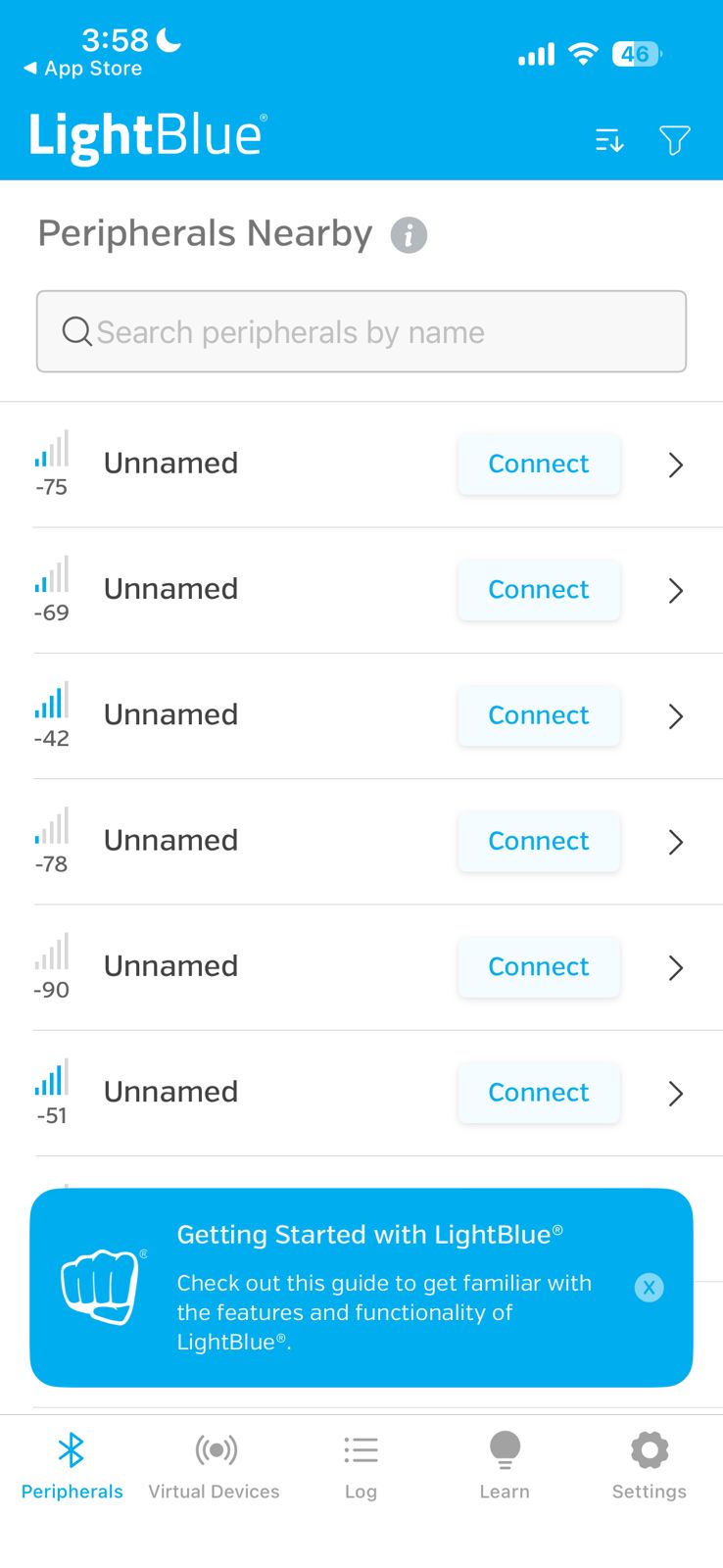
Scanning for nearby BLE devices using LightBlue before selecting the XIAO ESP32-C3 peripheral.
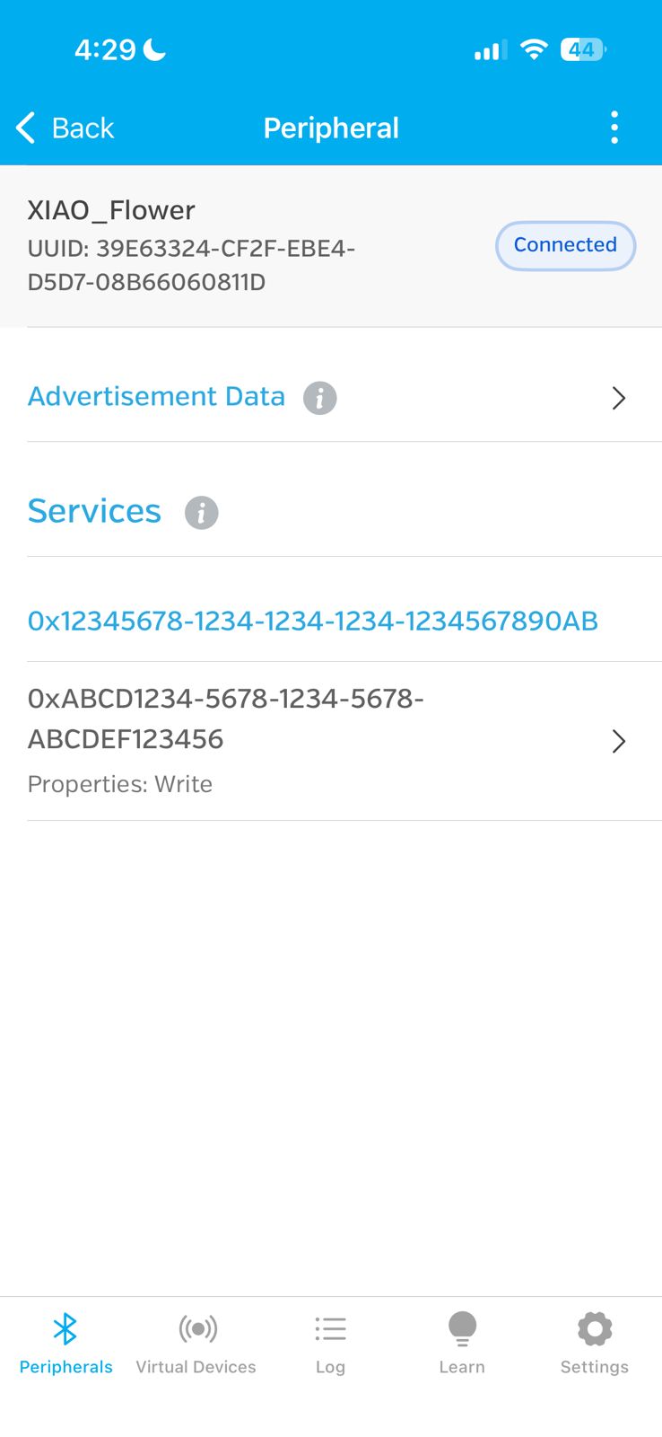
Successful connection to the device "XIAO_Flower", confirming that the BLE communication link is active.
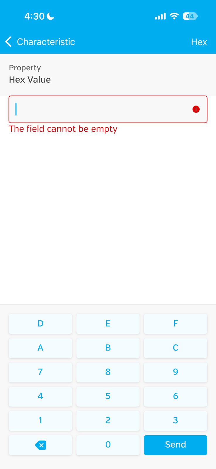
Attempt to write a value using Hex mode. This showed that the field required a valid value before sending data.
After accessing the writable characteristic, the communication format was changed to UTF-8 String in order to send text-based commands correctly.
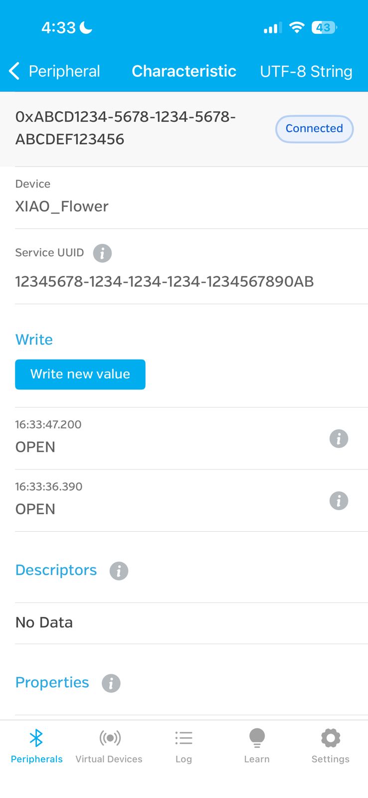
Writable BLE characteristic configured in UTF-8 String mode, allowing commands such as "OPEN" to be sent to the microcontroller.
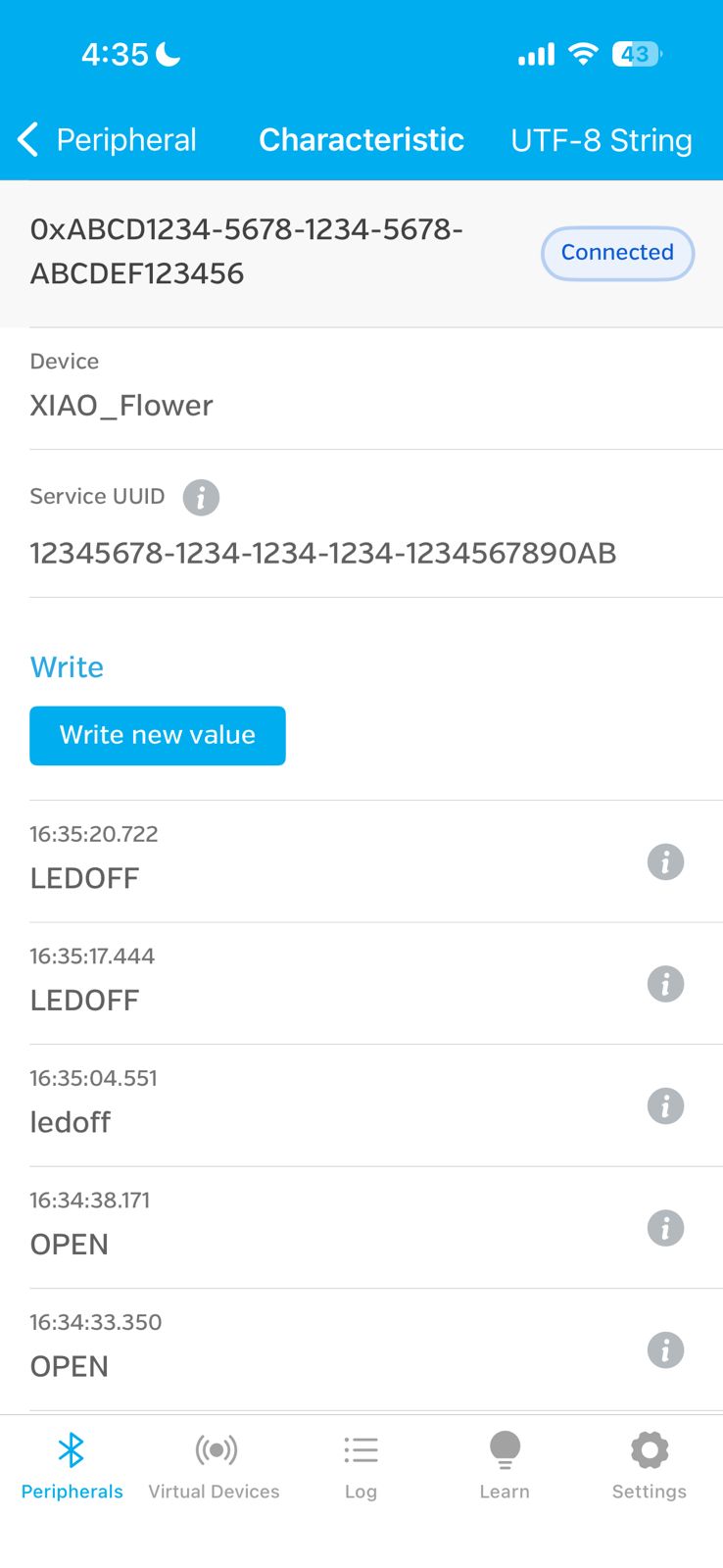
Command history showing transmitted values such as "OPEN" and "LEDOFF", confirming interaction between the mobile application and the system.
These results demonstrate real-time interaction between the mobile application and the embedded system, where user inputs are transmitted via BLE and translated into system responses.
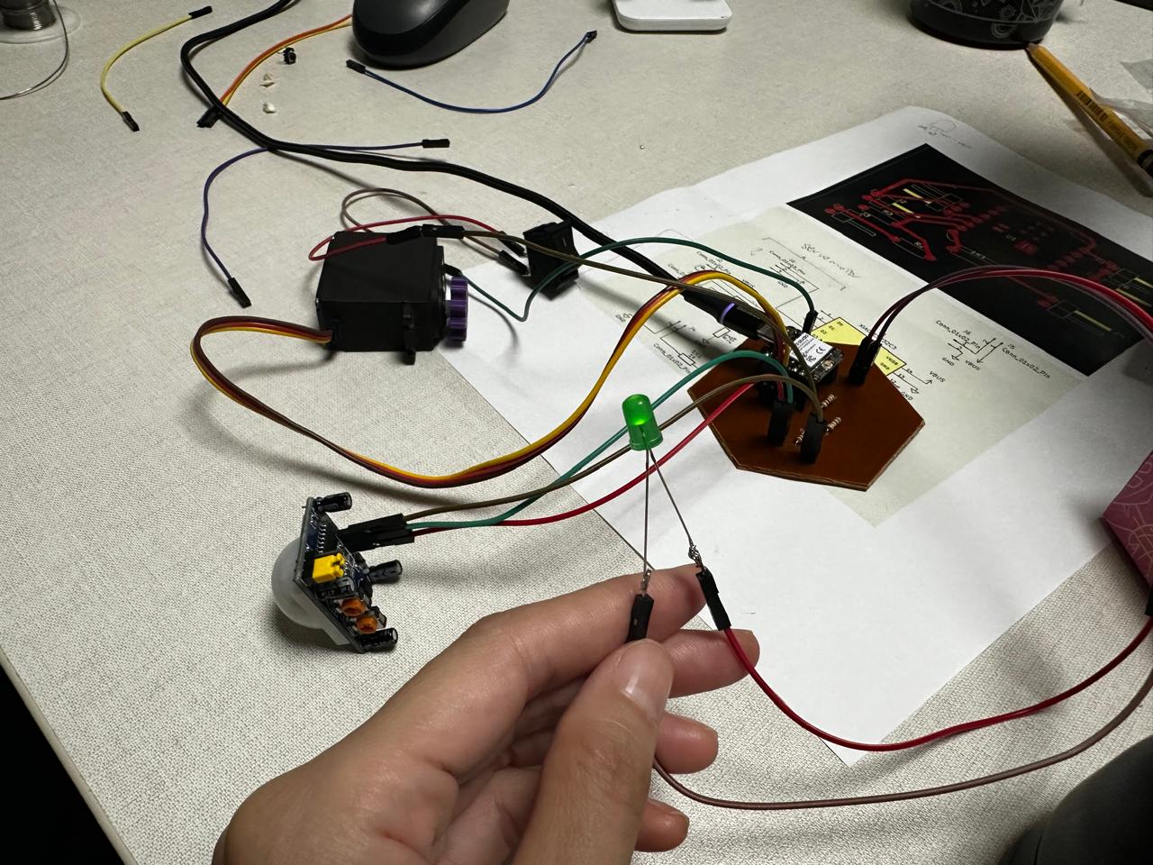
10. Physical Test
After establishing the BLE connection, I tested the system physically by sending commands from the smartphone while the XIAO ESP32-C3 was connected to the servo and the rest of the circuit.
The servo responded correctly when the OPEN and CLOSE commands were sent from the phone, which demonstrated successful wireless communication between the smartphone and the embedded device.
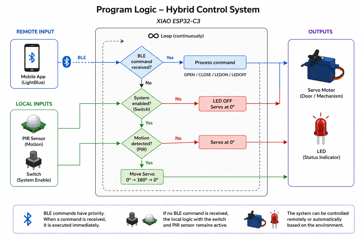
11. Program Logic
The diagram represents the hybrid control logic implemented in the system. The microcontroller continuously evaluates two types of inputs: remote commands received via BLE and local inputs from the switch and PIR sensor.
During testing, the PIR sensor was physically covered to prevent unwanted triggering, allowing the focus to be placed on manual control through the switch and remote interaction via Bluetooth.
If a BLE command is received, it is immediately executed, controlling the servo motor or LED. Otherwise, the system follows its local logic, where the switch enables operation and the PIR sensor (when active) can trigger automatic behavior.
This structure demonstrates how the system integrates both remote and physical interaction, even though certain inputs may be temporarily disabled during testing to improve stability.
12. Arduino Code
The Arduino program for the XIAO ESP32-C3 was developed with the assistance of ChatGPT. I used ChatGPT to help structure the Bluetooth Low Energy (BLE) communication, define the commands, and integrate the servo motor, LED, PIR sensor, and switch logic into a single program.
The prompt used to generate the base structure of the code was the following:
"Write an Arduino program for a XIAO ESP32-C3 that works as a BLE server. The device should receive text commands from a smartphone via Bluetooth Low Energy. Commands: OPEN -> move servo to open position. CLOSE -> move servo to closed position. LEDON -> turn LED on. LEDOFF -> turn LED off. The system should also read a PIR sensor and a switch. If the switch is on and the PIR detects motion, the servo should move automatically. Use pins: PIR -> D4 Switch -> D5 LED -> D6 Servo -> D3"
After generating the initial code, I modified and adjusted it to match the pin configuration, servo angles, and system behavior required for my project.
#define PIR_PIN D4
#define SWITCH_PIN D5
#define LED_PIN D6
#define SERVO_PIN D3

#include <ESP32Servo.h>
#include <BLEDevice.h>
#include <BLEUtils.h>
#include <BLEServer.h>

Servo myServo;

// UUIDs personalizados
#define SERVICE_UUID        "12345678-1234-1234-1234-1234567890ab"
#define CHARACTERISTIC_UUID "abcd1234-5678-1234-5678-abcdef123456"

String receivedCommand = "";

BLECharacteristic *pCharacteristic;

class MyCallbacks : public BLECharacteristicCallbacks {
  void onWrite(BLECharacteristic *pCharacteristic) {
    String value = pCharacteristic->getValue();

    if (value.length() > 0) {
      receivedCommand = value;
      receivedCommand.trim();

      Serial.print("Received BLE command: ");
      Serial.println(receivedCommand);
    }
  }
};

void setup() {
  Serial.begin(115200);

  pinMode(PIR_PIN, INPUT);
  pinMode(SWITCH_PIN, INPUT);
  pinMode(LED_PIN, OUTPUT);

  myServo.attach(SERVO_PIN);
  myServo.write(0);

  BLEDevice::init("XIAO_Flower");
  BLEServer *pServer = BLEDevice::createServer();

  BLEService *pService = pServer->createService(SERVICE_UUID);

  pCharacteristic = pService->createCharacteristic(
                      CHARACTERISTIC_UUID,
                      BLECharacteristic::PROPERTY_WRITE
                    );

  pCharacteristic->setCallbacks(new MyCallbacks());
  pService->start();

  BLEAdvertising *pAdvertising = BLEDevice::getAdvertising();
  pAdvertising->addServiceUUID(SERVICE_UUID);
  pAdvertising->start();

  Serial.println("BLE ready. Waiting for commands...");
}

void loop() {
  // BLE commands
  if (receivedCommand == "OPEN") {
    myServo.write(180);
    receivedCommand = "";
  }
  else if (receivedCommand == "CLOSE") {
    myServo.write(0);
    receivedCommand = "";
  }
  else if (receivedCommand == "LEDON") {
    digitalWrite(LED_PIN, HIGH);
    receivedCommand = "";
  }
  else if (receivedCommand == "LEDOFF") {
    digitalWrite(LED_PIN, LOW);
    receivedCommand = "";
  }

  // Original logic
  int encendido = digitalRead(SWITCH_PIN);
  Serial.print("boton: ");
  Serial.println(encendido);

  delay(200);

  if (encendido == 1) {
    digitalWrite(LED_PIN, HIGH);

    int estado = digitalRead(PIR_PIN);
    Serial.print("pir: ");
    Serial.println(estado);

    if (estado == 1) {
      delay(200);
      myServo.write(0);
      delay(1000);
      myServo.write(180);
      delay(1000);
    } else {
      myServo.write(0);
    }
  } else {
    digitalWrite(LED_PIN, LOW);
  }
}
Code Explanation
This program integrates Bluetooth Low Energy (BLE) communication with local input-output control, allowing the system to be operated both remotely (via mobile application) and locally (through sensors and a switch).
In the setup() function, the input pins (PIR sensor and switch) and output pins (LED and servo motor) are configured. The servo is initialized at 0°, and the BLE system is set up by defining a custom service and a writable characteristic. The device is initialized with the name "XIAO_Flower" and starts advertising, making it discoverable by mobile applications.
A callback class (MyCallbacks) is implemented to handle incoming BLE data. When a value is written to the characteristic, the function onWrite() is triggered, storing the received command as a string and printing it to the Serial Monitor.
In the loop(), the program first checks for received BLE commands. Commands such as "OPEN" and "CLOSE" control the servo position, while "LEDON" and "LEDOFF" control the LED state. After executing each command, the variable is reset to avoid repeated execution.
In addition to BLE control, the program maintains its original logic based on physical inputs. The switch acts as a system enable condition: when it is active, the LED turns on and the PIR sensor is evaluated. If motion is detected, the servo performs a movement between 0° and 180°. If no motion is detected, the servo returns to its initial position.
This dual control structure demonstrates how a system can combine wireless commands and real-time sensor input, enabling flexible interaction through both remote and physical interfaces.
Results
The final result was a working BLE communication system between a smartphone and the XIAO ESP32-C3. Through this communication, I was able to remotely control the servo motor and the LED.
This assignment demonstrated:
- Wireless embedded communication using Bluetooth Low Energy
- Communication between a smartphone and a microcontroller
- Remote control of actuators
- Integration of networking, programming, sensors, and outputs
Conclusion
This week helped me understand how embedded systems can communicate wirelessly using BLE. I learned how to configure the XIAO ESP32-C3 as a BLE server, define services and characteristics, and use a smartphone as a BLE client.
I also found it interesting to combine this communication system with my previous electronic setup, since it allowed me to control the project both automatically and manually. This will be very useful for my final project, where interaction, responsiveness, and communication between devices are important.
Reflection
At the beginning, setting up Bluetooth communication was a bit confusing, especially when dealing with BLE services, characteristics, and the data format used by the mobile application. One of the first issues I encountered was that the LightBlue app was configured in Hex mode, which prevented me from sending text commands correctly. After understanding the correct format and adjusting the settings to UTF-8 string, the communication started to work properly.
This assignment made me realize how powerful wireless communication can be in interactive projects. It also helped me see that communication is not only about sending data, but also about designing how different parts of a system interact.
Download Files
The design files used in this assignment can be downloaded below.