
Week 04 | Embedded Programming
Group Assignment
This week's group assignment consisted of analyzing the microcontroller architecture used in our laboratory. The objective was to understand the main characteristics of the microcontroller, including its architecture, memory structure, peripherals, and programming capabilities.
We explored the ESP32-C3 microcontroller integrated in the Seeed Studio XIAO ESP32-C3 development board, reviewing its technical documentation, pinout, and hardware features used for embedded programming.
The complete documentation of the group work can be found in the following page:
Group assignment documentation
Individual Assignment
The objective of this assignment was to understand the basic process of programming a microcontroller using Arduino IDE and verify the behavior of a digital output by controlling an external LED connected on a breadboard.
Through this exercise, I explored the typical embedded programming workflow: connecting the hardware, writing the code, uploading the program to the microcontroller, and verifying the behavior of the circuit.
1. Hardware Used
The following components were used in this activity:
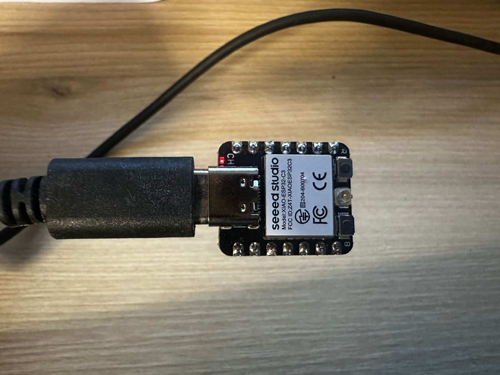
- Seeed Studio XIAO ESP32-C3 development board
- Breadboard
- Red LED
- Current-limiting resistor
- Jumper wires
- USB-C cable for power and programming
The XIAO ESP32-C3 is a compact development board based on the ESP32-C3 microcontroller. It can be programmed using Arduino IDE and provides several GPIO pins that can be configured as digital inputs or outputs.
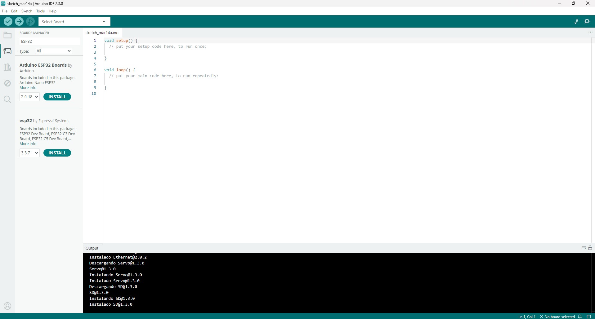
2. Programming Environment Setup
The first step was to install and configure the Arduino IDE. After that, the correct board definition for the XIAO ESP32-C3 was selected and the serial port assigned to the board was configured.
At the beginning of the process, I encountered some issues related to board selection and the use of the built-in LED definition. After selecting the correct XIAO ESP32-C3 board and testing the communication through the Serial Monitor, I confirmed that the microcontroller was correctly running uploaded programs.
3. Circuit Design
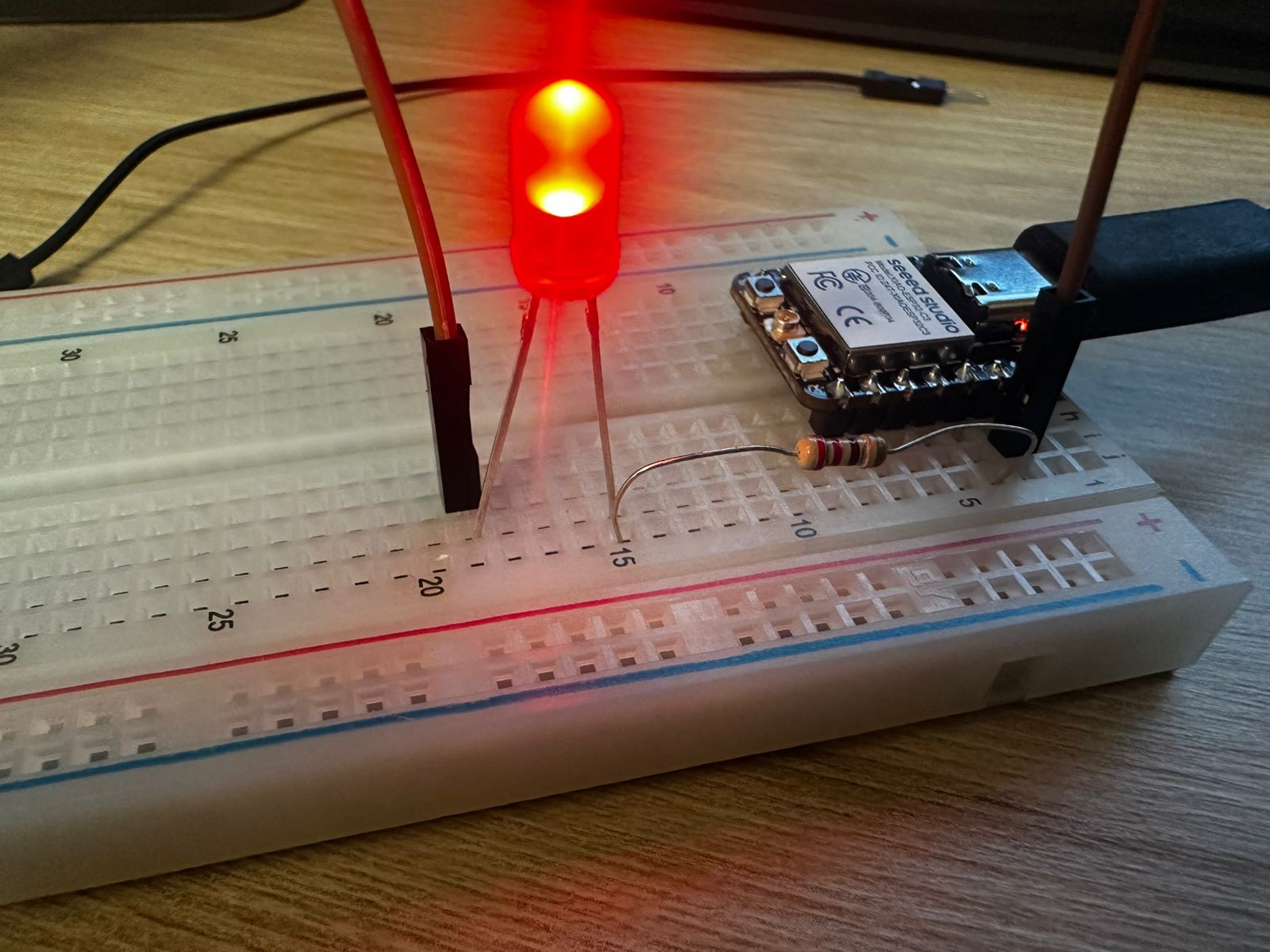
To test the microcontroller output, I built a simple circuit on a breadboard. The goal was to control an external LED using one of the digital pins of the XIAO board.
The circuit was connected as follows:
- A digital pin from the XIAO was connected to a current-limiting resistor.
- The resistor was connected to the anode of the LED.
- The cathode of the LED was connected to the GND pin of the microcontroller.
The resistor is necessary to limit the current flowing through the LED and protect both the LED and the microcontroller.
This type of circuit is one of the most common tests in embedded programming because it quickly verifies whether the microcontroller is executing the uploaded program correctly.
4. Microcontroller Fundamentals
Before programming the system, it is important to understand the basic principles of how a microcontroller interacts with hardware and how it can be programmed to control external components.
A microcontroller operates by reading inputs, processing information, and generating outputs through configurable pins. These pins are not fixed in their function; instead, they can be assigned different roles such as digital input, digital output, or communication interfaces depending on the program.
Additionally, the way in which the microcontroller is programmed can vary depending on the level of abstraction used. High-level environments such as Arduino simplify interaction with hardware, while lower-level approaches such as Embedded C provide more direct control over the internal architecture of the device.
Understanding these concepts is essential to correctly configure the hardware connections and to develop programs that effectively control physical systems.
4.1 Microcontroller Pins Based on the Datasheet
For this assignment, I used the Seeed Studio XIAO ESP32-C3, which is based on the ESP32-C3 microcontroller. According to the ESP32-C3 datasheet, the chip includes configurable GPIO pins that can be assigned to different functions such as digital input, digital output, ADC, UART, SPI, I2C and PWM, depending on the configuration used in the program.
In this exercise, I used pin D2 of the XIAO ESP32-C3 as a digital output. In the XIAO ESP32-C3 pinout, D2 corresponds to GPIO5. This pin was connected to a current-limiting resistor and then to the anode of the external LED. The cathode of the LED was connected to GND.
The ESP32-C3 GPIO system allows each pin to be configured by software. In this case, the pin was configured as an output using the pinMode() function. Once configured, the voltage level of the pin could be changed between HIGH and LOW using digitalWrite(), allowing the LED to turn on and off.
To verify the pin mapping and understand the relationship between the board labels and the internal GPIO configuration, I consulted the official XIAO ESP32-C3 pinout documentation:
XIAO ESP32-C3 Pinout Sheet (Seeed Studio)
References used:
- Seeed Studio XIAO ESP32-C3 pinout documentation.
- Espressif ESP32-C3 Series Datasheet.
In this assignment, these concepts were applied to control a simple LED circuit using a digital output pin.
4.2 Comparison: Arduino vs Embedded C
Before implementing the code, it is useful to understand the difference between the programming approaches available for microcontrollers. While this project was developed using Arduino IDE for simplicity and rapid prototyping, other approaches such as Embedded C offer more direct control over the hardware. The following comparison highlights the main differences between these two approaches.
| Aspect | Arduino | Embedded C |
|---|---|---|
| Level of abstraction | Higher level. It uses simplified functions such as pinMode(), digitalWrite() and delay(). |
Lower level. It usually requires direct control of registers and hardware configuration. |
| Ease of use | Easier for beginners because the syntax is simpler and many hardware details are already handled by the Arduino core. | More complex because the programmer needs to understand the microcontroller architecture in more detail. |
| Control over hardware | Less direct control, but faster for prototyping. | More direct control over memory, registers, timing and peripherals. |
| Development speed | Faster for simple tests and prototypes. | Slower at the beginning, but more powerful for optimized embedded systems. |
| Use in this assignment | Arduino was useful because it allowed me to quickly test the GPIO output and verify the LED circuit. | Embedded C would be useful if I needed more precise control over the ESP32-C3 hardware or wanted to optimize memory and timing. |
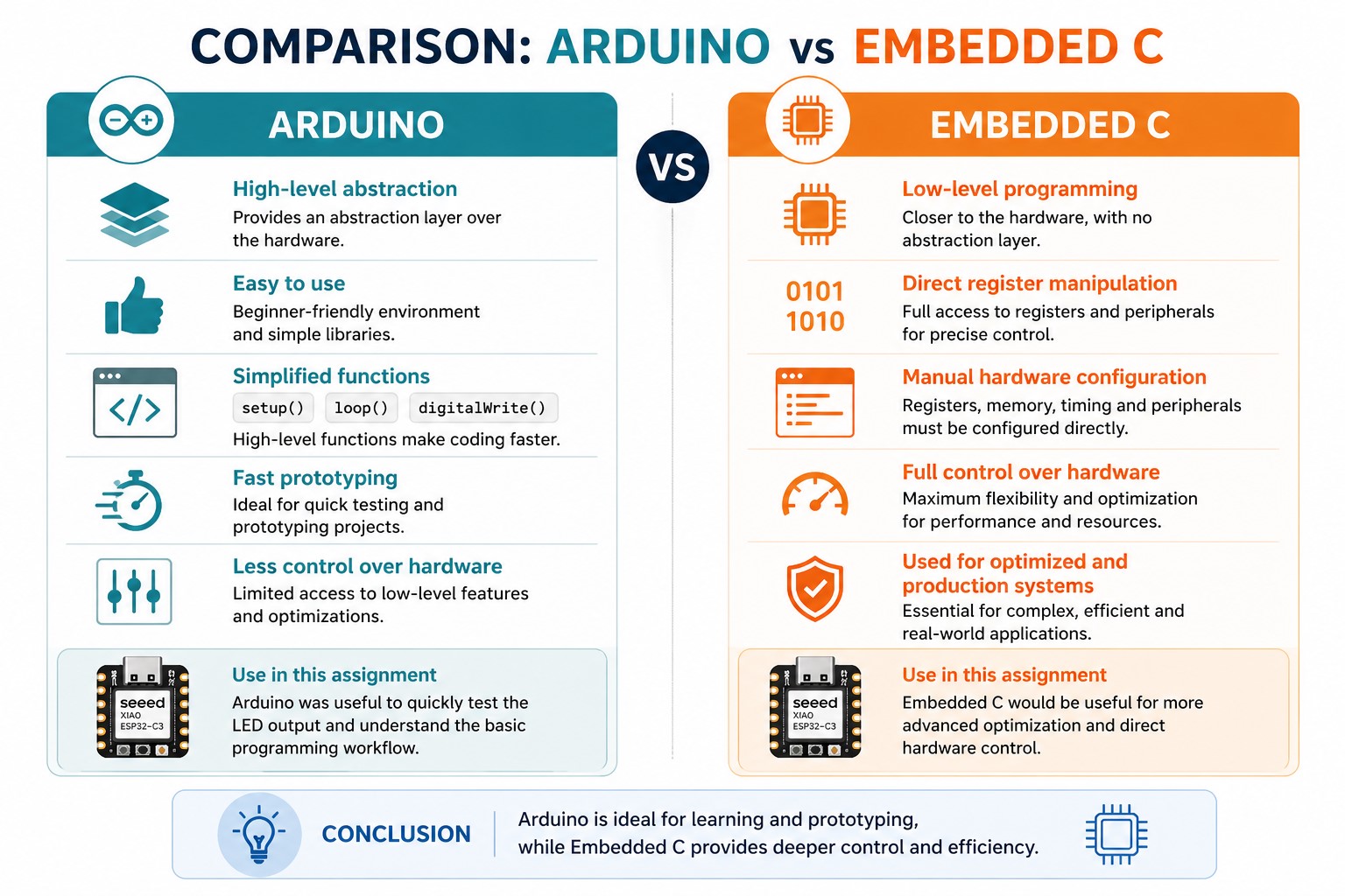
For this first exercise, Arduino IDE was appropriate because the objective was to understand the basic workflow of programming a microcontroller and controlling a physical output. However, embedded C provides deeper access to the microcontroller architecture and is more suitable for advanced applications where optimization and direct hardware control are required.
5. Code Used
The following code was uploaded to the board in order to control the LED:
						#define LED_PIN D2

						void setup() {
						pinMode(LED_PIN, OUTPUT);
						}

						void loop() {
						digitalWrite(LED_PIN, HIGH);
						delay(500);
						digitalWrite(LED_PIN, LOW);
						delay(500);
						}
Code Explanation Line by Line
#define LED_PIN D2
This line creates a constant name called LED_PIN and assigns it to pin D2 of the board. This makes the code easier to understand because instead of writing the pin number several times, I can use the name LED_PIN.
void setup() {
The setup() function runs only once when the microcontroller is powered on or reset. It is used to configure the initial conditions of the program.
pinMode(LED_PIN, OUTPUT);
This line configures the selected pin as a digital output. This means the microcontroller can send a HIGH or LOW signal through this pin.
}
This closes the setup() function.
void loop() {
The loop() function runs continuously after the setup() function finishes. Everything inside this function repeats while the board is powered.
digitalWrite(LED_PIN, HIGH);
This sends a HIGH signal to the selected pin. As a result, voltage is applied to the LED circuit and the LED turns on.
delay(500);
This pauses the program for 500 milliseconds, so the LED remains on for half a second.
digitalWrite(LED_PIN, LOW);
This sends a LOW signal to the selected pin. The voltage is removed from the LED circuit and the LED turns off.
delay(500);
This pauses the program again for 500 milliseconds, so the LED remains off for half a second.
}
This closes the loop() function. After this, the program returns to the beginning of the loop and repeats the blinking sequence.
This code directly controls the physical LED connected to pin D2, demonstrating how a software instruction translates into a hardware response.
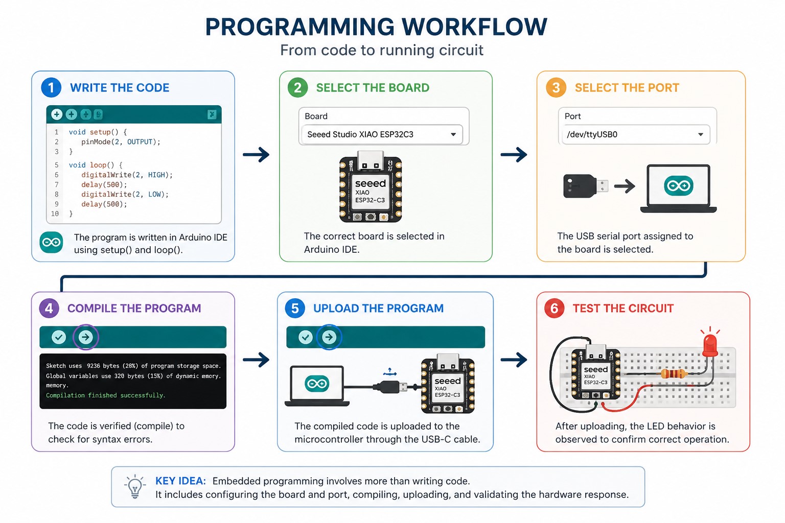
6. Programming Workflow: Compile and Upload
The programming process followed a basic embedded programming workflow using Arduino IDE:
- Connect the board: The XIAO ESP32-C3 was connected to the computer using a USB-C cable.
- Select the board: In Arduino IDE, I selected the correct board configuration for the XIAO ESP32-C3.
- Select the port: I selected the serial port assigned to the connected microcontroller.
- Write the code: I wrote a simple blinking LED program using a digital output pin.
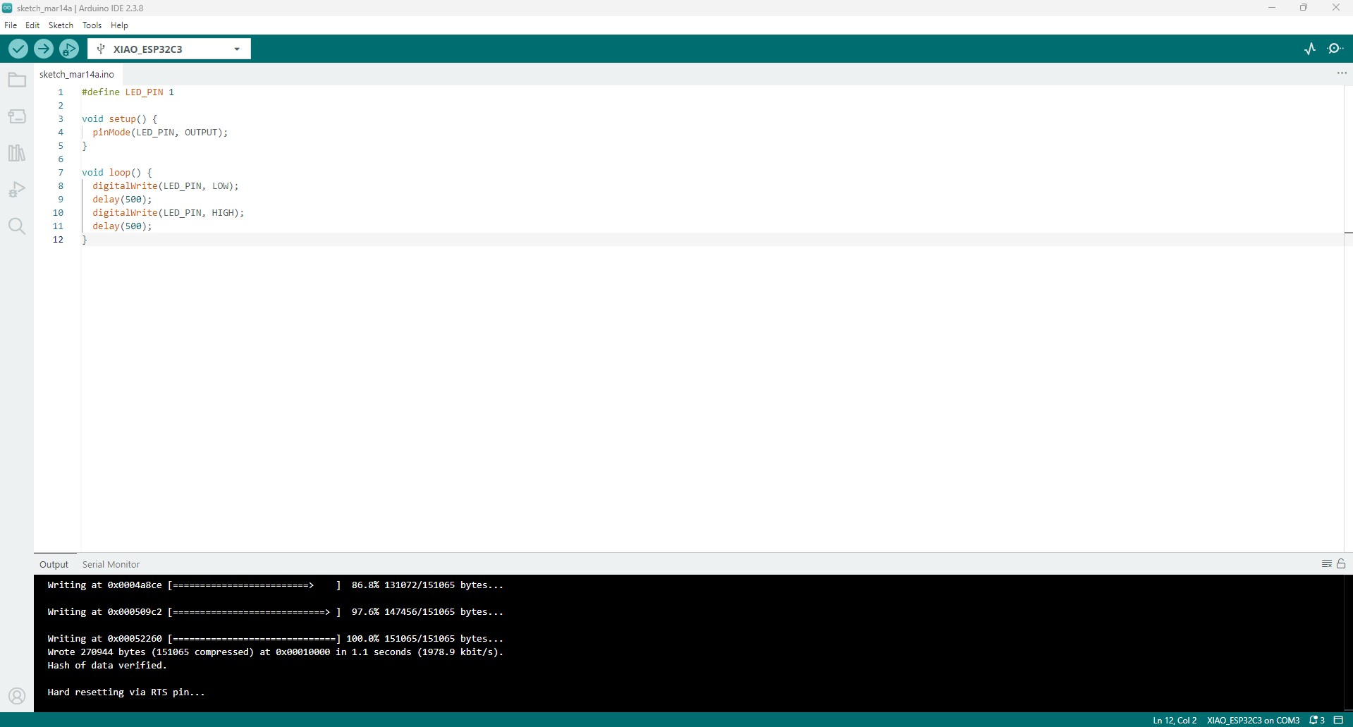
- Compile the code: I clicked the Verify button in Arduino IDE. This checked the syntax and converted the code into machine-readable instructions for the microcontroller.
- Upload the code: I clicked the Upload button. The compiled program was transferred from the computer to the XIAO ESP32-C3 through the USB connection.
- Test the circuit: After uploading, I observed the external LED blinking, which confirmed that the program was running correctly.
7. Results
After uploading the program, the LED connected to the digital pin turned on successfully, confirming that the board was correctly programmed and that the circuit was properly connected.
This result demonstrated that the microcontroller was able to control an external component through a digital output pin. It also confirmed that the programming environment, hardware connections, and power supply were working correctly.
8. Debugging Issues
During the assignment, I encountered some issues while programming and testing the XIAO ESP32-C3. The first issue was related to the board selection in Arduino IDE. If the incorrect board was selected, the code could compile but the upload process did not work correctly. To solve this, I reviewed the board configuration and selected the XIAO ESP32-C3 option.
Another issue was identifying the correct pin to use for the external LED. The physical label on the board does not always match the internal GPIO number of the ESP32-C3. For that reason, I checked the XIAO ESP32-C3 pinout and confirmed the relationship between the board pin and the microcontroller GPIO.
I also verified the LED polarity and resistor connection on the breadboard. If the LED is placed backwards or the circuit is not connected to GND correctly, the program may be running but the LED will not turn on. After checking the wiring, I confirmed that the anode was connected to the output pin through the resistor and the cathode was connected to GND.
Finally, I used the upload messages in Arduino IDE as a debugging reference. A successful upload confirmed that the board was communicating with the computer, while the blinking LED confirmed that the program was running correctly on the microcontroller.
What I Learned
Through this exercise, I learned the basic workflow required to program a microcontroller using Arduino IDE, including board selection, code compilation, program upload, and hardware testing.
I also learned how to configure a GPIO pin as a digital output and how to control its state through code in order to interact with an external electronic component.
In addition, this activity reinforced my understanding of breadboard-based prototyping and the importance of using a current-limiting resistor when working with LEDs.
Reflection
This assignment helped me better understand the relationship between software and hardware in an embedded system. Even though the circuit was simple, it represented an important first step in learning how to interact with physical components through a microcontroller.
The process also required several tests and adjustments, especially when identifying the correct board configuration and verifying the external LED connection. This trial-and-error process was useful to understand that debugging is a natural part of embedded programming and electronics prototyping.
As a next step, I would like to continue exploring more advanced input and output interactions, such as push buttons, sensors, and multiple output devices connected to the XIAO ESP32-C3.