
Week 02 — Computer-Aided Design
Week Reflection
This week was especially interesting, enjoyable, and challenging. Exploring the possibilities of digital modeling to achieve organic forms proved to be far more complex than it initially seemed. I began by experimenting with simple and more rigid geometries, exploring radial structures and modular repetitions. These initial explorations helped me understand how curves and surfaces behave within the digital environment.
The process became an intentional exploration of the available tools to achieve the form I was seeking. I tested different operations and combinations to create smoother transitions and more natural curvatures. After multiple iterations, I developed a petal form with an organic character that conveys lightness, movement, and sensitivity. The model was then translated into 2D vector geometry to evaluate its fabrication feasibility and organize the components required for production. This step revealed how three-dimensional form must be simplified and structured for digital cutting processes.
Finally, rendering the model allowed me to evaluate materiality, depth, and the interaction of light with curved surfaces, helping to assess the aesthetic presence of the object before physical fabrication. This process demonstrated that digital design is not linear: it requires exploration, iteration, and a continuous dialogue between form, technique, and perception.
Learning Outcomes
- Evaluate and select 2D and 3D software
- Demonstrate and describe processes used in modelling with 2D and 3D softwares
- Demonstrate image and video compression
Evaluation and Selection of 2D and 3D Software
Different software tools were evaluated based on their role in the digital fabrication workflow. The selection criteria included precision, ease of use, compatibility with fabrication processes, and integration between tools.
2D Vector Software
| Software | Main Use | Advantages | Limitations |
|---|---|---|---|
| Adobe Illustrator | Vector editing for laser cutting and engraving | High precision, layer control, color-based workflows | Not specifically designed for fabrication |
| Inkscape | Open-source vector editing (SVG) | Free, widely compatible with digital fabrication | Less stable and less optimized than Illustrator |
| CorelDRAW | Laser cutting workflows | Direct compatibility with some laser cutter software | Limited use outside laser workflows |
| AutoCAD (2D) | Technical drafting and precise 2D drawings | Highly precise, industry standard | Less flexible for creative vector editing |
3D Modeling Software
| Software | Main Use | Advantages | Limitations |
|---|---|---|---|
| Rhinoceros (Rhino) | Freeform and precise 3D modeling | High precision, flexible geometry, ideal for fabrication | Not fully parametric |
| Fusion 360 | Parametric design and CAM | Integrated CAD + CAM, parametric workflow | Requires internet, heavier software |
| Autodesk Inventor | Mechanical design and engineering | Strong parametric modeling, assembly simulation | Less flexible for organic forms |
| Blender | Organic modeling and rendering | Very powerful for complex and artistic shapes | Not precise for fabrication measurements |
| Archicad | Architectural modeling (BIM) | Good for building-scale design and documentation | Not suitable for small-scale fabrication |
| SolidWorks | Mechanical and product design | Industry standard, strong parametric tools | Expensive, less flexible for freeform design |
Software Selection Rationale
Based on this evaluation, the selected workflow for this project was:
- Rhino for 3D modeling and geometry development
- Illustrator for 2D vector preparation and fabrication setup
This combination allows a flexible yet precise workflow, enabling the transition from 3D design to fabrication-ready 2D files while maintaining control over geometry and tool paths. Additionally, these are the tools I feel most confident and comfortable using, which allows me to effectively translate my ideas into physical results.
This evaluation highlights that no single tool covers the entire workflow. Instead, combining specialized tools improves efficiency and precision in digital fabrication processes, while also reinforcing my confidence in applying them to develop and materialize my projects.
Design and Fabrication Workflow
1. Conceptual Geometry Exploration
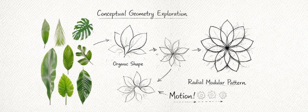
The process began with the exploration of forms inspired by natural structures, particularly the radial organization of flower petals and leaves.
The exploration focused on:
- radial symmetry
- modular repetition
- layered structures
- opening and closing possibilities
Sketching helped reveal how a simple form can evolve into a dynamic system.
2. 3D Modeling and Fabrication-Oriented Design
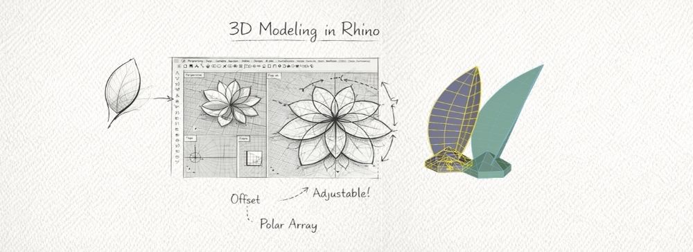
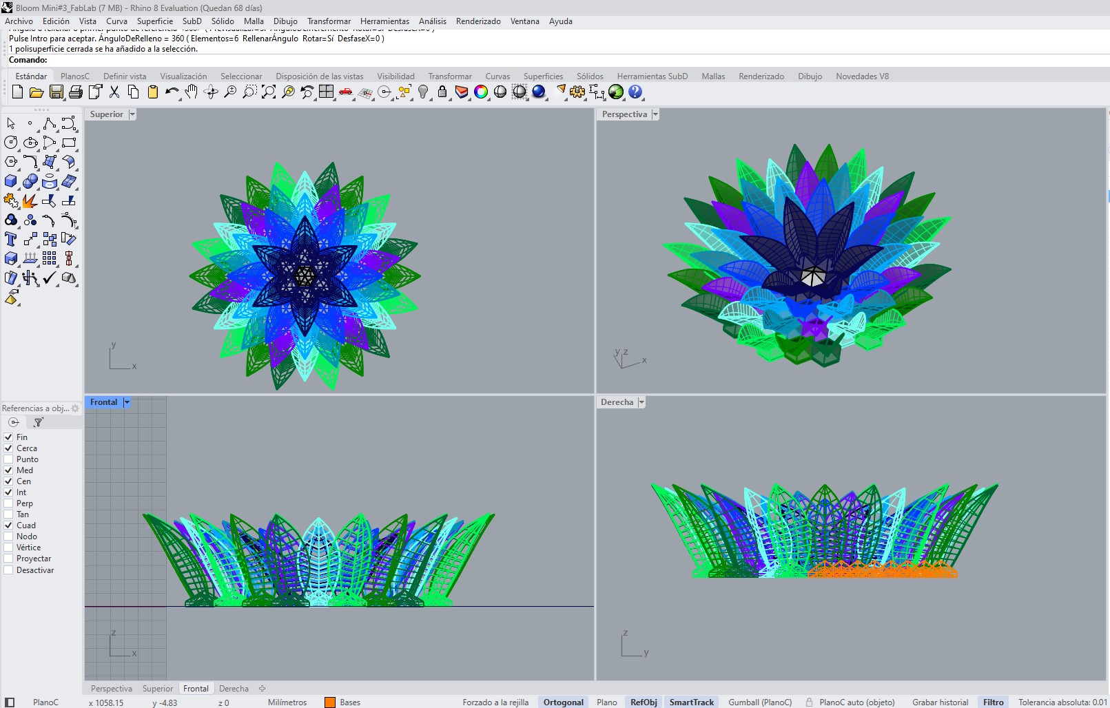
The development of this piece was carried out using Rhinoceros 3D with the objective of creating a modular structure intended for 3D printing. The design consists of two main elements: a repetitive hexagonal base and a set of curved leaves oriented toward the center of the geometry.
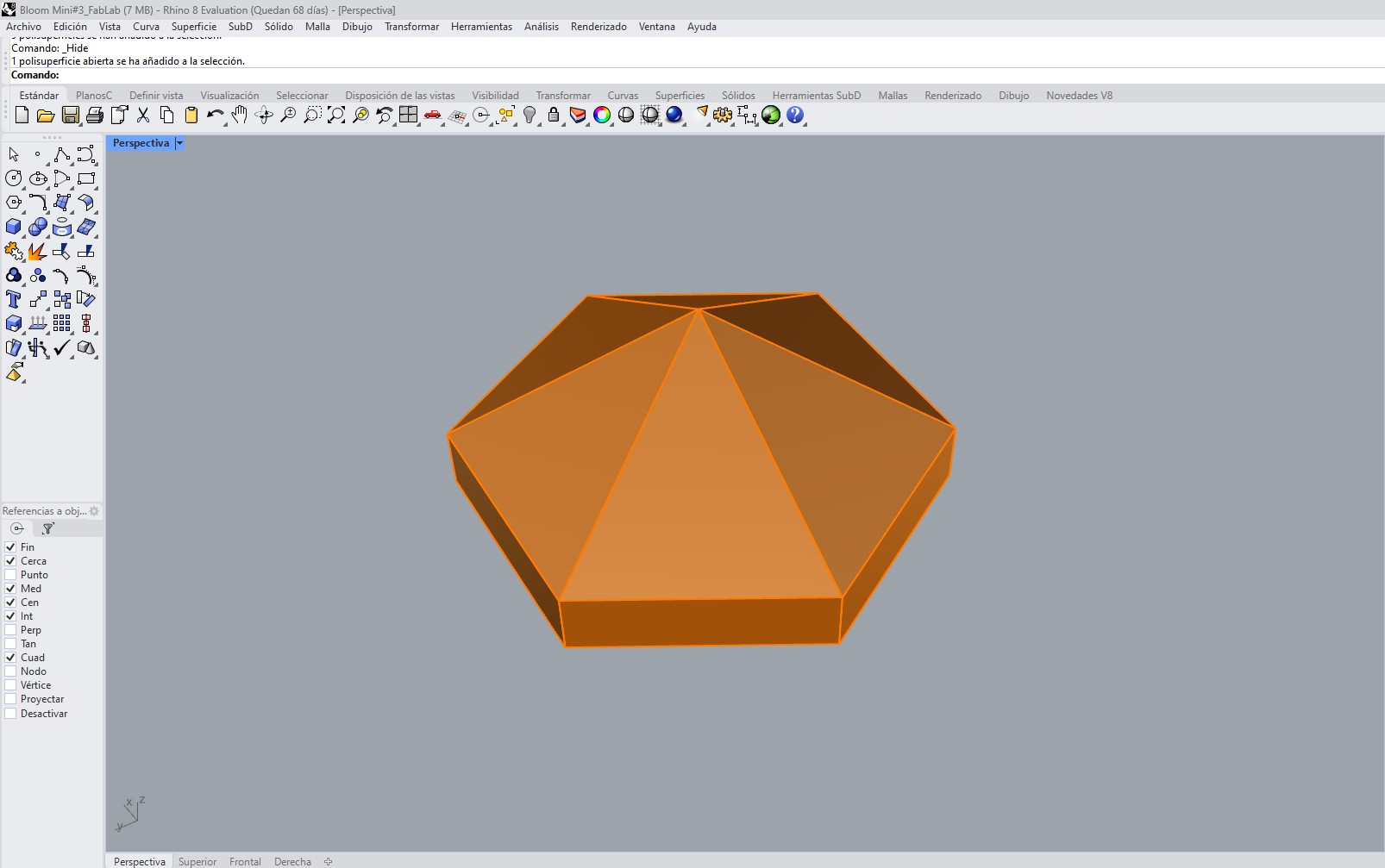
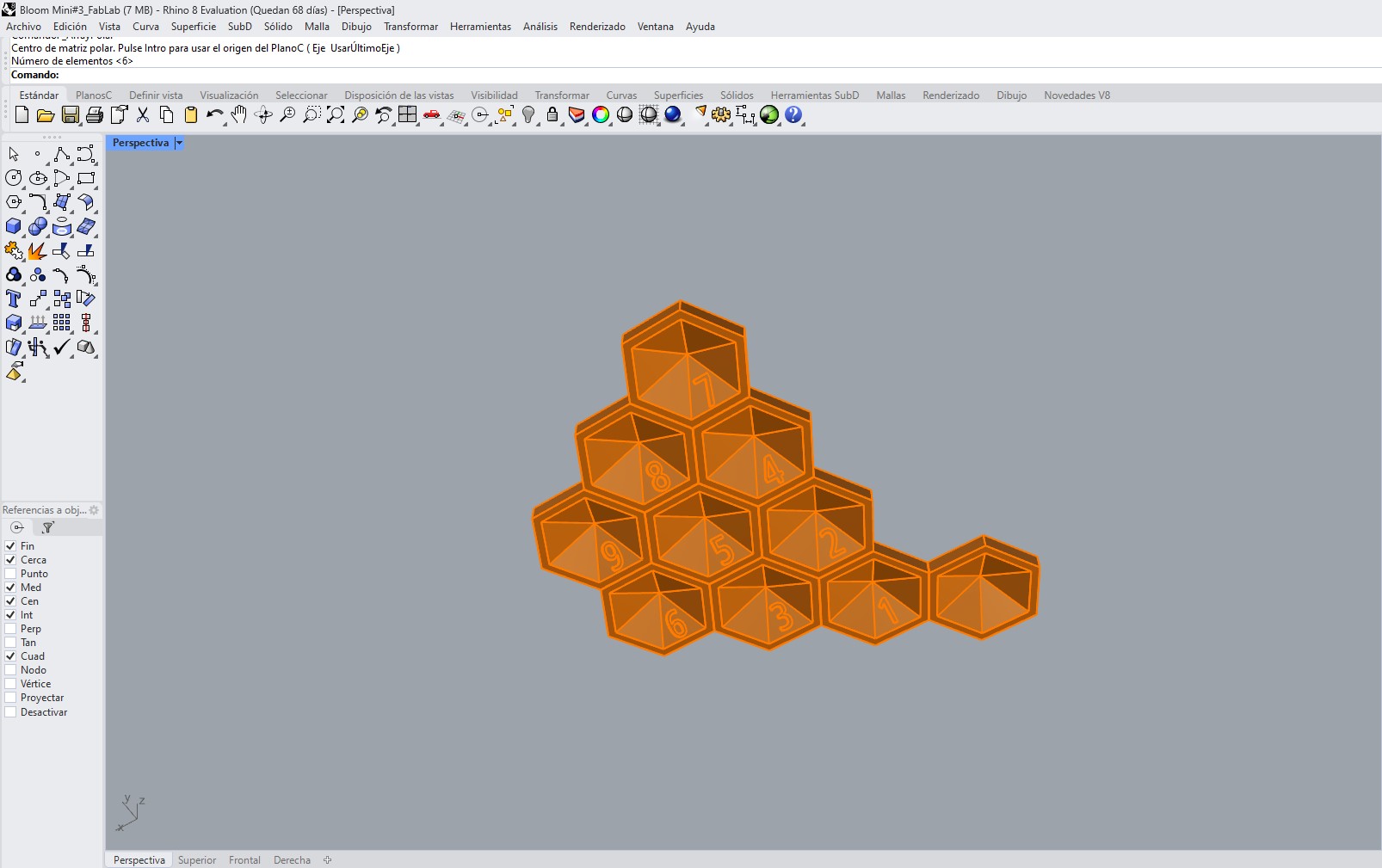
A. Design of the Hexagonal Base Module
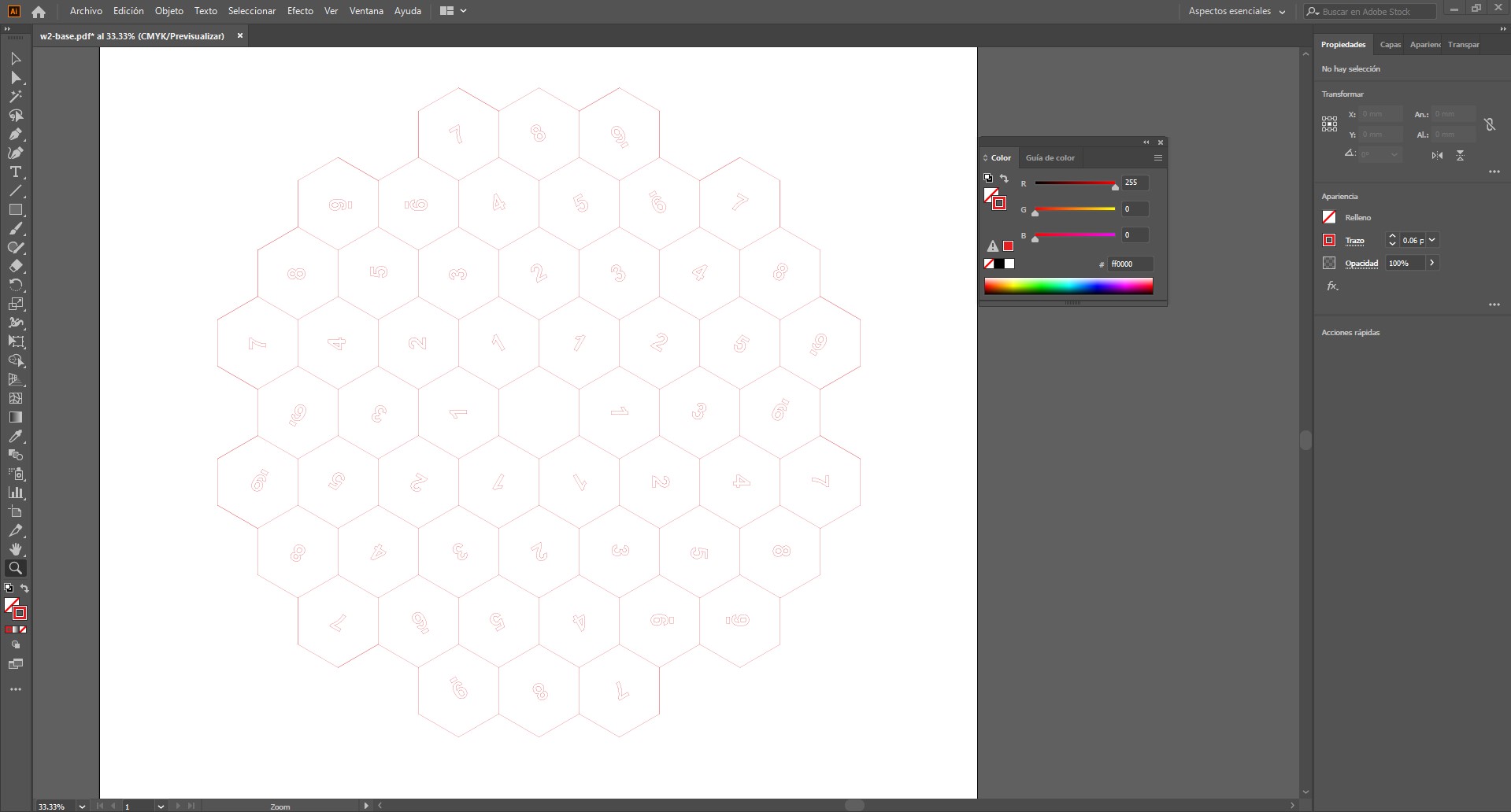
The process began with the creation of a hexagonal base module. This module functions as the fundamental unit of the system, as its replication generates the entire structural base. The hexagon was selected due to its tessellation capability, allowing the design to expand seamlessly without gaps.
Each module was numbered to identify its position within the assembly and to facilitate the correct placement of the corresponding leaf. This numbering system ensured a clear relationship between each base and the specific orientation of its associated leaf.
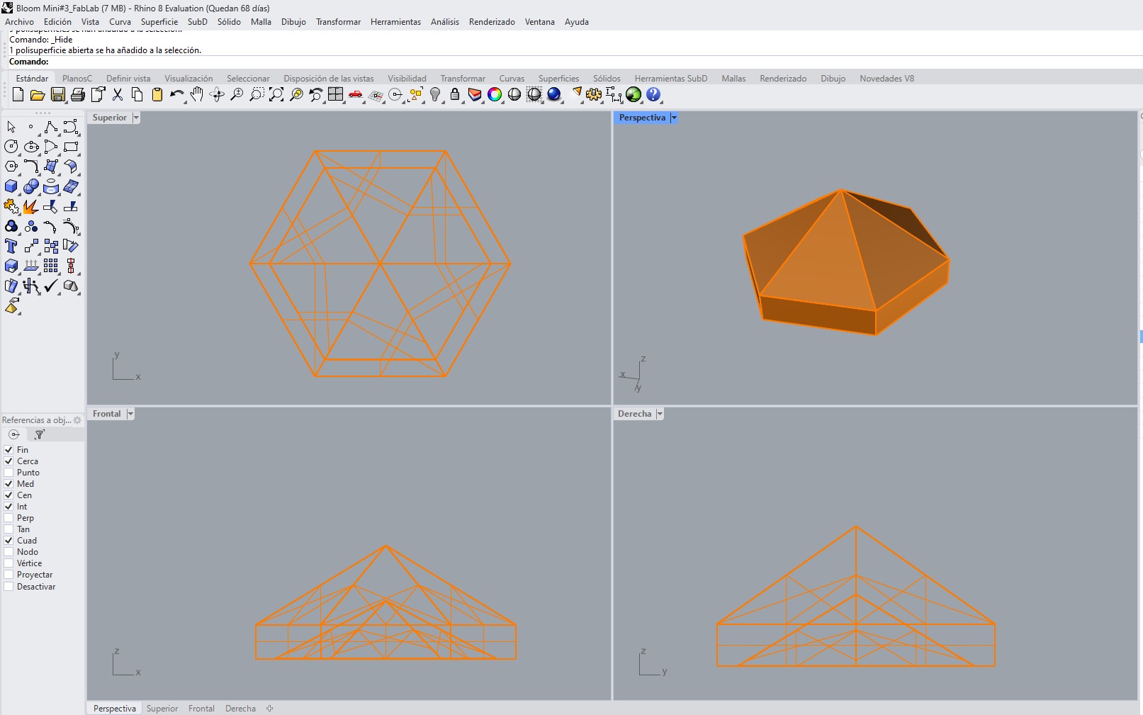
B. Replication of the Modular System
Once the base module was defined, it was duplicated and arranged to form the complete structure. The repetition of the hexagonal unit ensured geometric consistency and dimensional accuracy throughout the entire assembly.
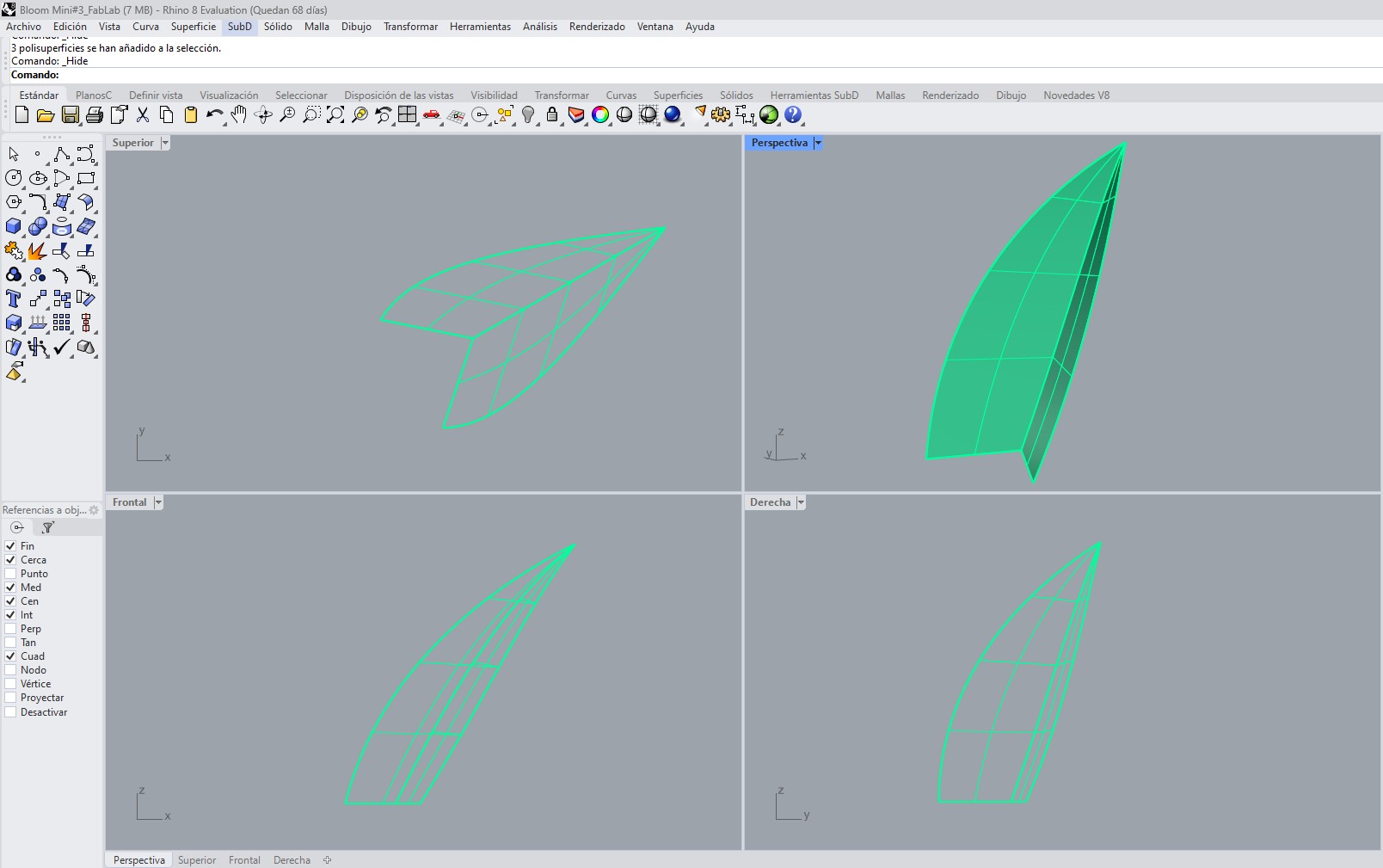
C. Leaf Design Using Sweep 2 Rails
The leaf geometry was created using the Sweep 2 Rails tool in Rhinoceros. This method allowed the generation of a smooth and organic surface defined by two guiding rails and several cross-sectional profiles, resulting in a natural and controlled shape.
D. Thickness Assignment
An offset thickness of 0.4 mm was applied to the surface using the Offset Surface command. This value was selected to ensure that the leaves were sufficiently thin and flexible, enabling post-processing deformation through heat after 3D printing while maintaining structural integrity.
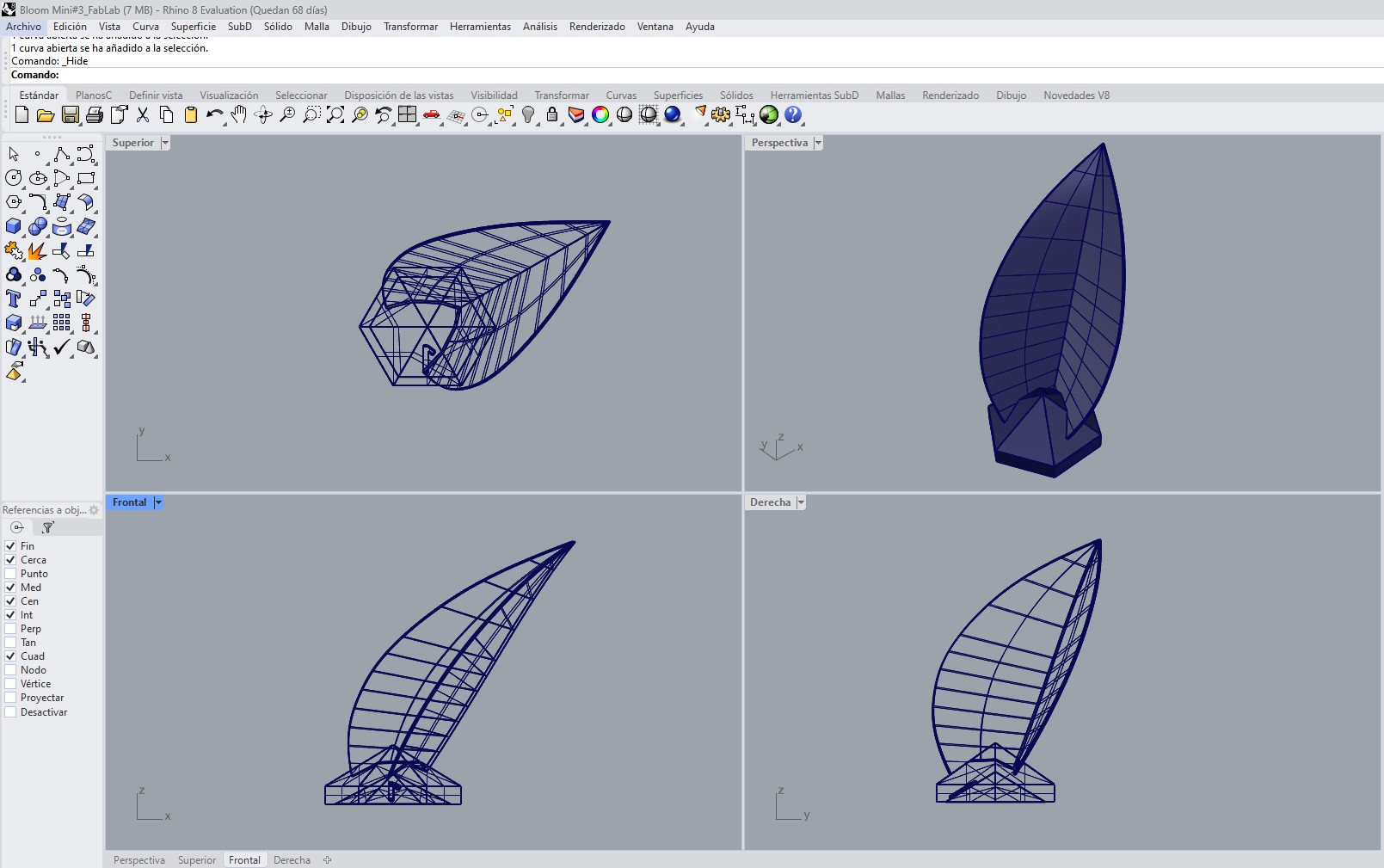
E. Variation in Leaf Orientation
Although the base geometry of the leaf is identical, its orientation varies depending on its position within the assembly. Each leaf was rotated and adjusted so that it points toward the center of the composition, creating a harmonious radial arrangement.
Due to these variations, nine distinct leaves were designed, each corresponding to a specific position within one sector of the model. This set of nine leaves was then replicated six times using a polar array, completing the overall geometry of the piece.
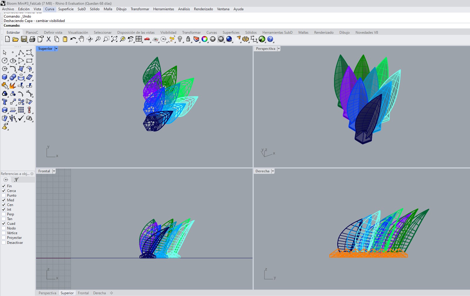
F. Leaf Integration and System Assembly
Each leaf was positioned on its corresponding hexagonal module, ensuring proper alignment and stability. The prior numbering of the modules facilitated this process, allowing a precise association between the base and the orientation of each leaf. In total, 9 unique leaf variations were designed and then replicated 6 times each to complete the full composition.
G. Preparation for 3D Printing
Finally, the complete model was reviewed to ensure its suitability for 3D printing. Surface continuity, proper intersections, and watertight geometry were verified. The final design was exported in STL format, ready for processing in slicing software.
Download Files
The design files used in this assignment can be downloaded below.
- Download 3dm - Rhino 3D model
- Download stl - flower
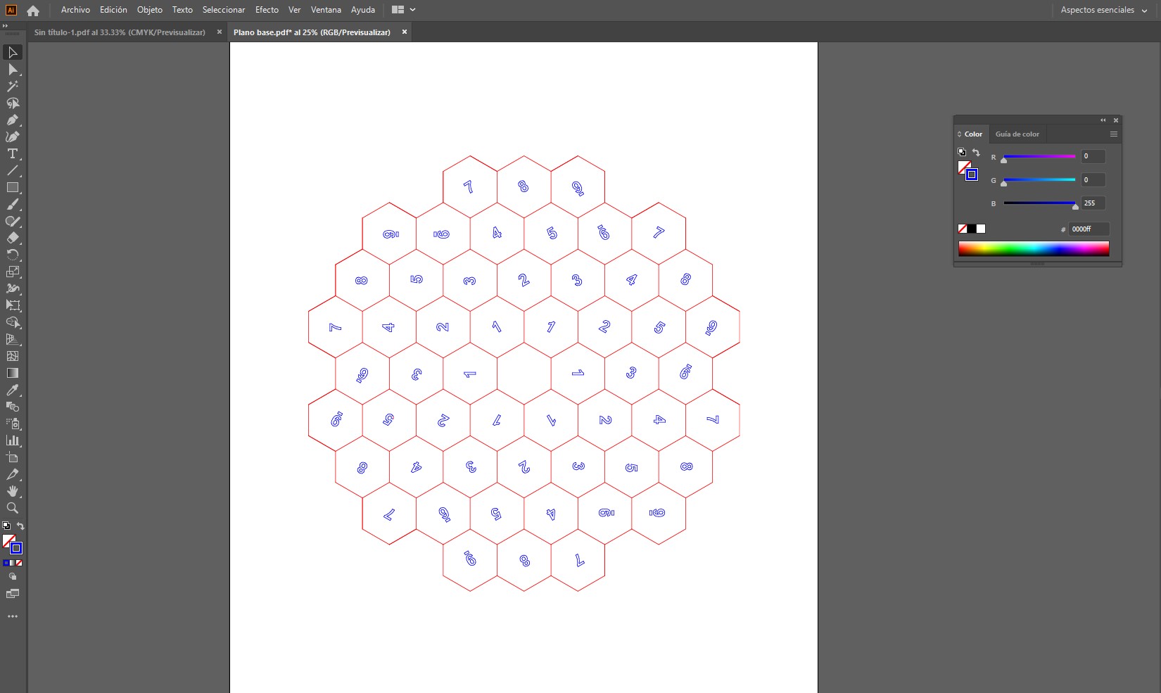
- Cleaning duplicated or unnecessary lines: After exporting from Rhino, some lines were duplicated or overlapped. These redundant geometries were removed to prevent the machine from cutting the same path twice, which could lead to inaccuracies, excessive burning, or unnecessary fabrication time.
- Organizing geometry according to operation type: The vectors were organized according to the intended fabrication process, distinguishing between cutting lines and marking lines. This made it easier to assign different machine parameters later.
- Adjusting line weights:
Since the file included both cutting and marking operations, both types of lines
were drawn using thin line weights, as required by laser cutting workflows. In this case, the difference between
the operations was not defined by line thickness, but by color:
- Red lines were used for cutting
- Blue lines were used for marking
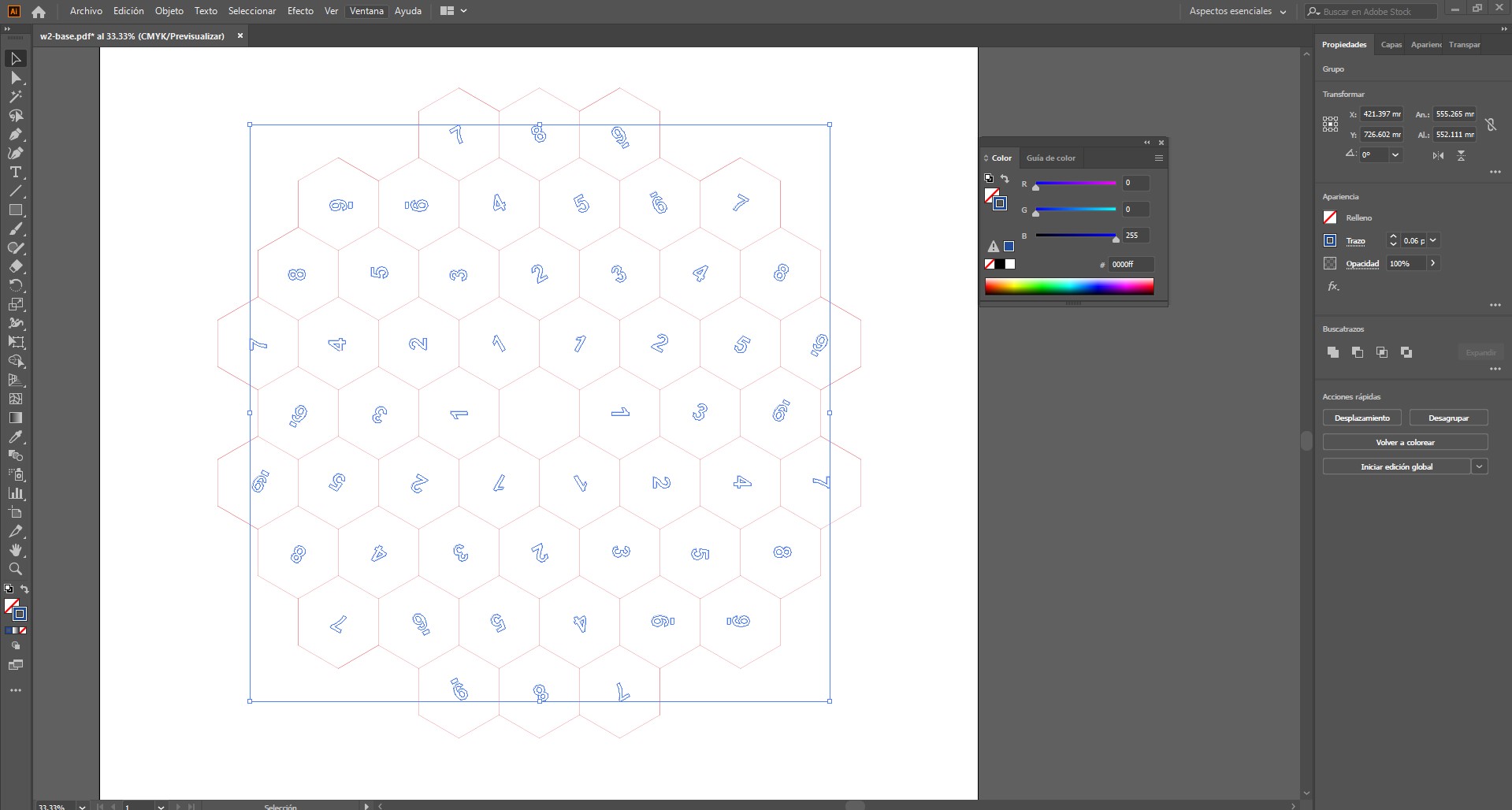 This color coding allows the machine software to apply different settings, such as power, speed, or number of passes,
depending on the operation. Using thin lines ensures that the machine follows the vector paths precisely.
This color coding allows the machine software to apply different settings, such as power, speed, or number of passes,
depending on the operation. Using thin lines ensures that the machine follows the vector paths precisely.
- Optimizing tool paths: The continuity of the geometry was checked to make sure paths were clean and connected where necessary. This reduces machine errors and improves fabrication efficiency.
- Checking scale and dimensions: The exported file was verified to make sure that dimensions remained correct after transferring the geometry from Rhino to Illustrator. This is important to avoid scaling problems during fabrication.
- Preparing the file for machine compatibility: Finally, the vector file was left ready to be exported in a format compatible with the machine workflow, ensuring that all geometry, colors, and path definitions were preserved correctly.
- Download pdf - base
- Download illustrator - base
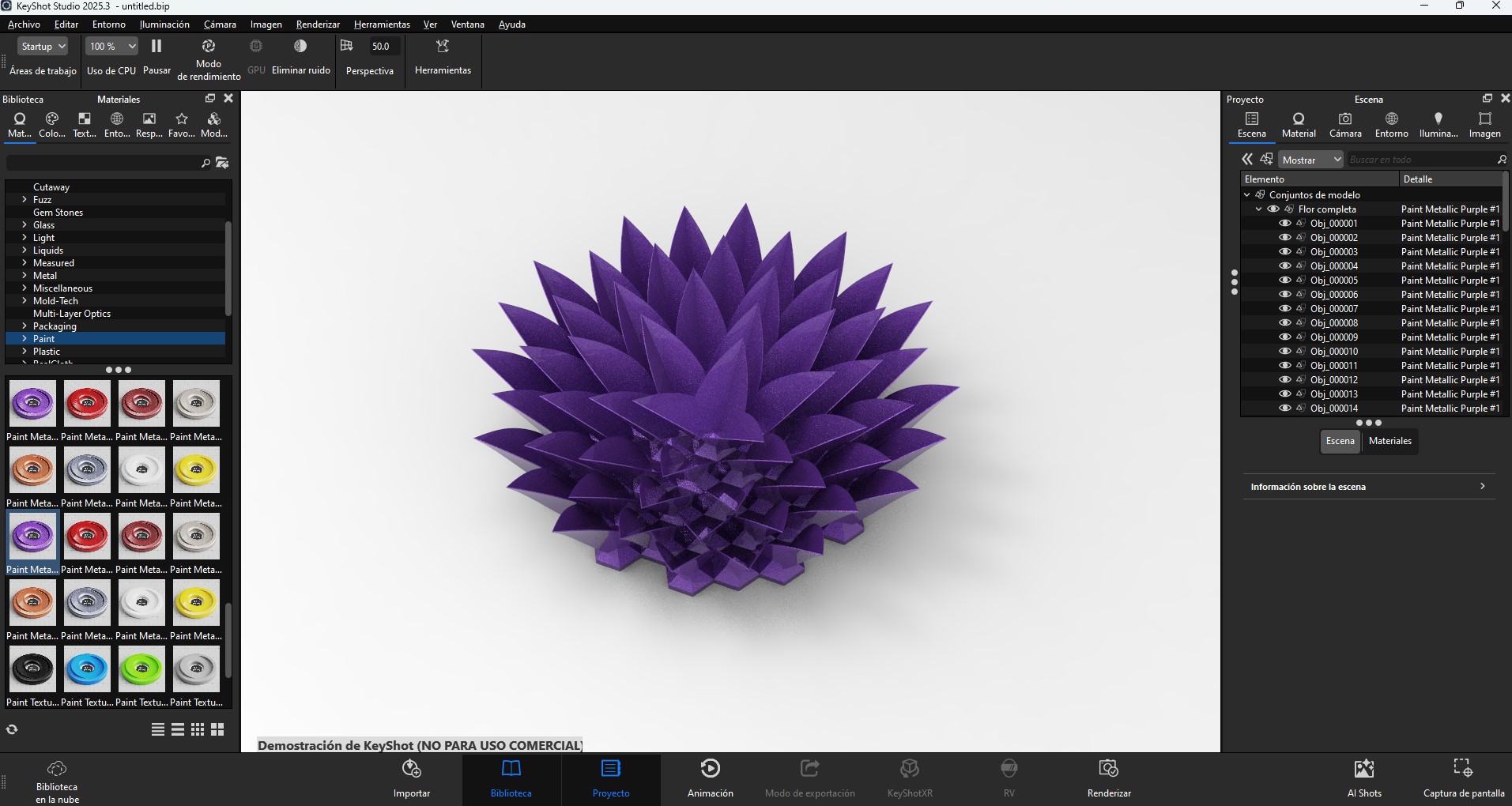
- applying materials to simulate real finishes
- exploring lighting to emphasize volume and depth
- analyzing how light interacts with curved surfaces
- producing renderings to communicate the design
- The website loads quickly
- The repository size remains manageable
- Users can easily access and download files
- The documentation remains clear and professional
3. 2D Vector Preparation (Rhino → Illustrator)
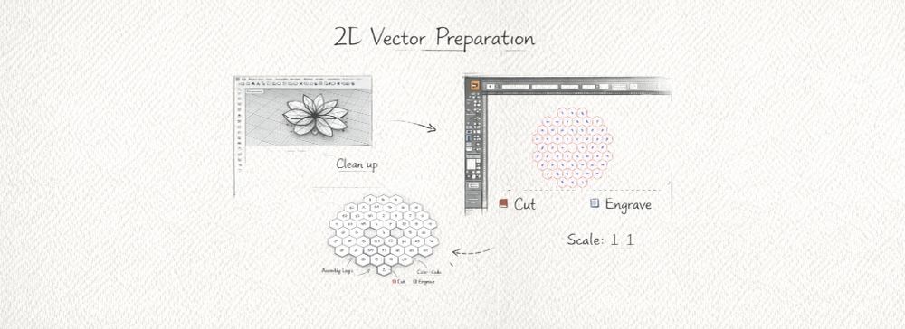
Once the 3D modeling stage was completed in Rhino, the geometries were exported into a 2D format for fabrication. This step is essential because digital fabrication machines such as laser cutters and CNC machines operate based on vector paths in two dimensions.
The vector preparation was carried out in Adobe Illustrator, where the file was cleaned, organized, and optimized before being sent to the machine. This stage was necessary to make sure the design could be interpreted correctly by the fabrication software and executed accurately during production.
Preparation Process
During this stage, several adjustments were made to ensure the vector file was ready for fabrication:
Importance of this Step
This stage is critical in the digital fabrication workflow because it ensures that the digital design can be correctly interpreted by the machine. Poor vector preparation can result in inaccurate cuts, duplicated toolpaths, wasted material, longer fabrication times, or even failed production.
Proper 2D vector preparation guarantees precision, efficiency, and a cleaner final result. It also creates a clear transition between the design phase and the fabrication phase, making the workflow more reliable and controlled.
Download Files
The design files used in this assignment can be downloaded below.
4. Visualization and Rendering
The 3D model was exported to KeyShot to generate realistic visualizations that helped evaluate form, materiality, and perception.
This stage included:
5. Compressed Files and Media Optimization
To improve the performance of the website and keep the repository size manageable, all media files were optimized and compressed before being uploaded. This is an important step in Fab Academy documentation, since large files can significantly slow down page loading and make navigation less efficient.
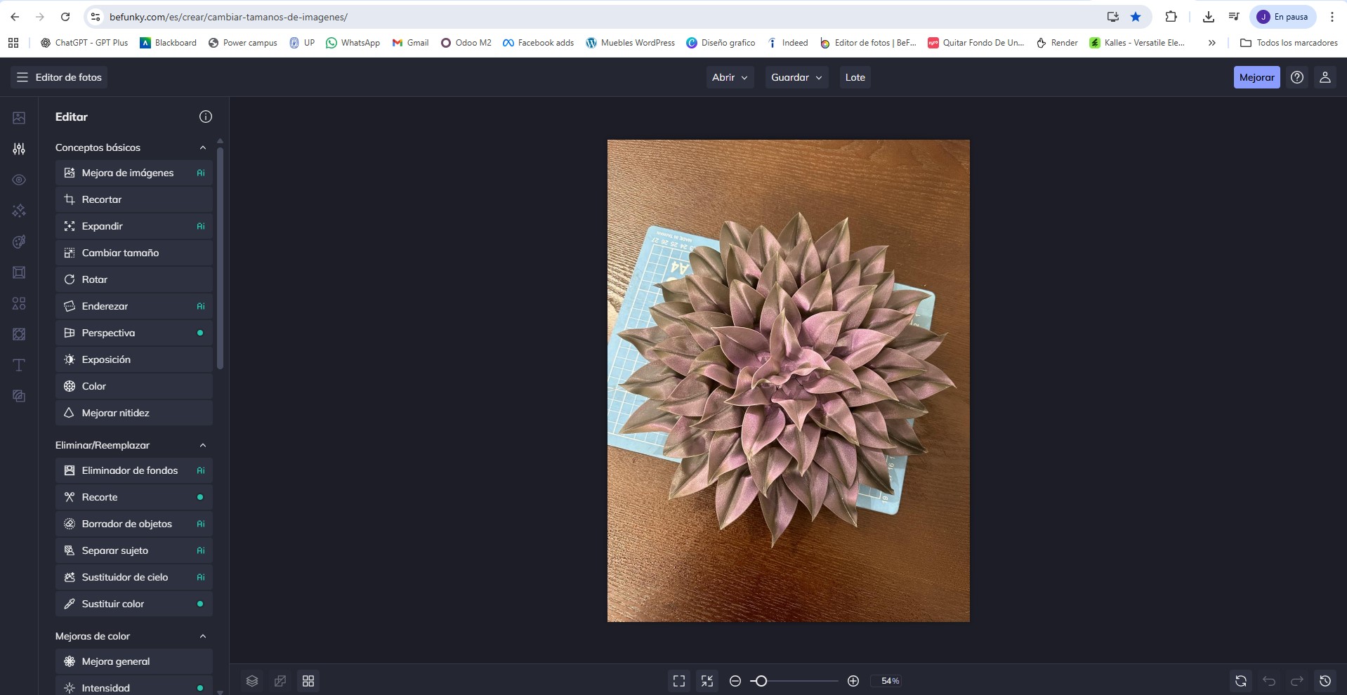
Image Optimization
Images were resized and compressed when necessary using the online tool BeFunky. This allowed reducing file size while maintaining sufficient resolution to clearly document the fabrication process, details of the components, and final results.
The goal was to balance visual quality and performance, ensuring that images load quickly without losing important information.
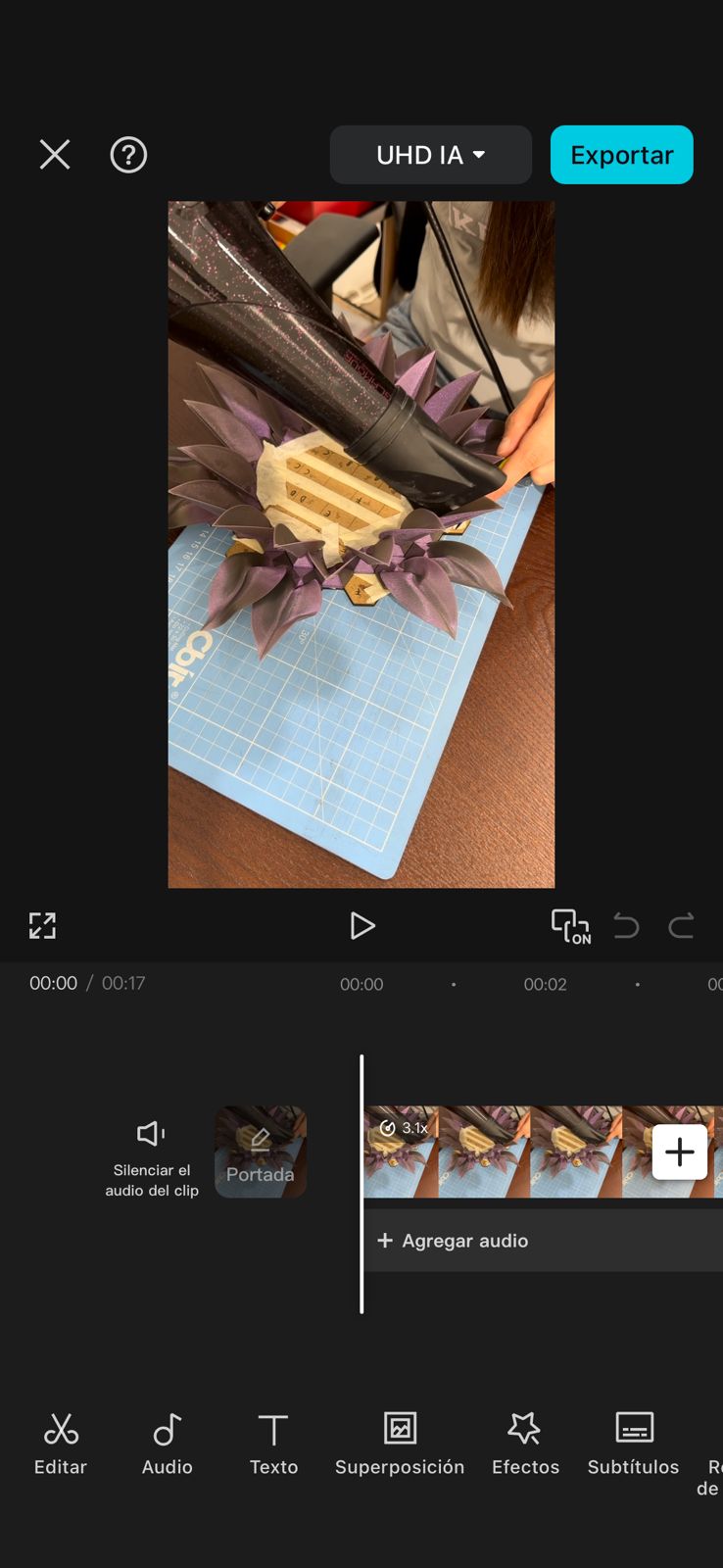
Video Compression
Videos were compressed using CapCut. This tool made it possible to significantly reduce file size while preserving acceptable visual quality.
Video compression was especially important because raw video files tend to be very large. By compressing them, it was possible to include video documentation of the system behavior (such as testing and interaction) without affecting website performance.
Compression of Design Files
Larger files such as design files, project folders, and fabrication resources were compressed using 7-Zip. This allowed grouping multiple files into a single compressed archive, making them easier to download and share.
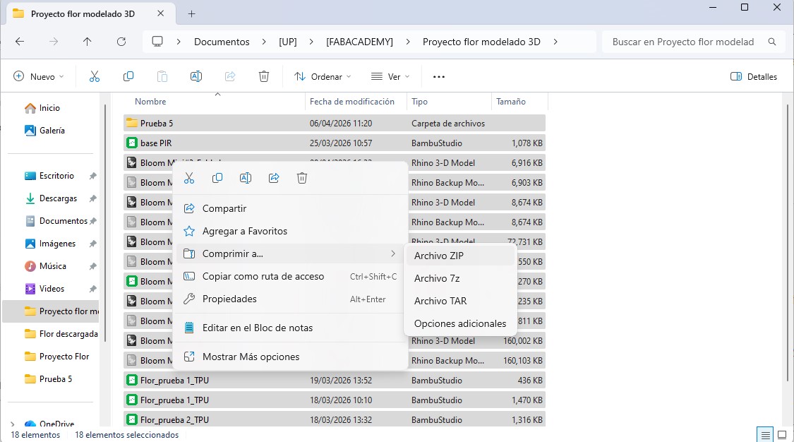
Using compressed archives also helps maintain a cleaner repository structure and avoids uploading unnecessary large file collections individually.
Importance of File Optimization
These optimization steps are essential for maintaining an efficient and well-organized documentation. They ensure that:
Overall, file compression and optimization are key practices in digital documentation, especially when working with media-rich content such as images, videos, and design files.
6. Parametric Design Exploration
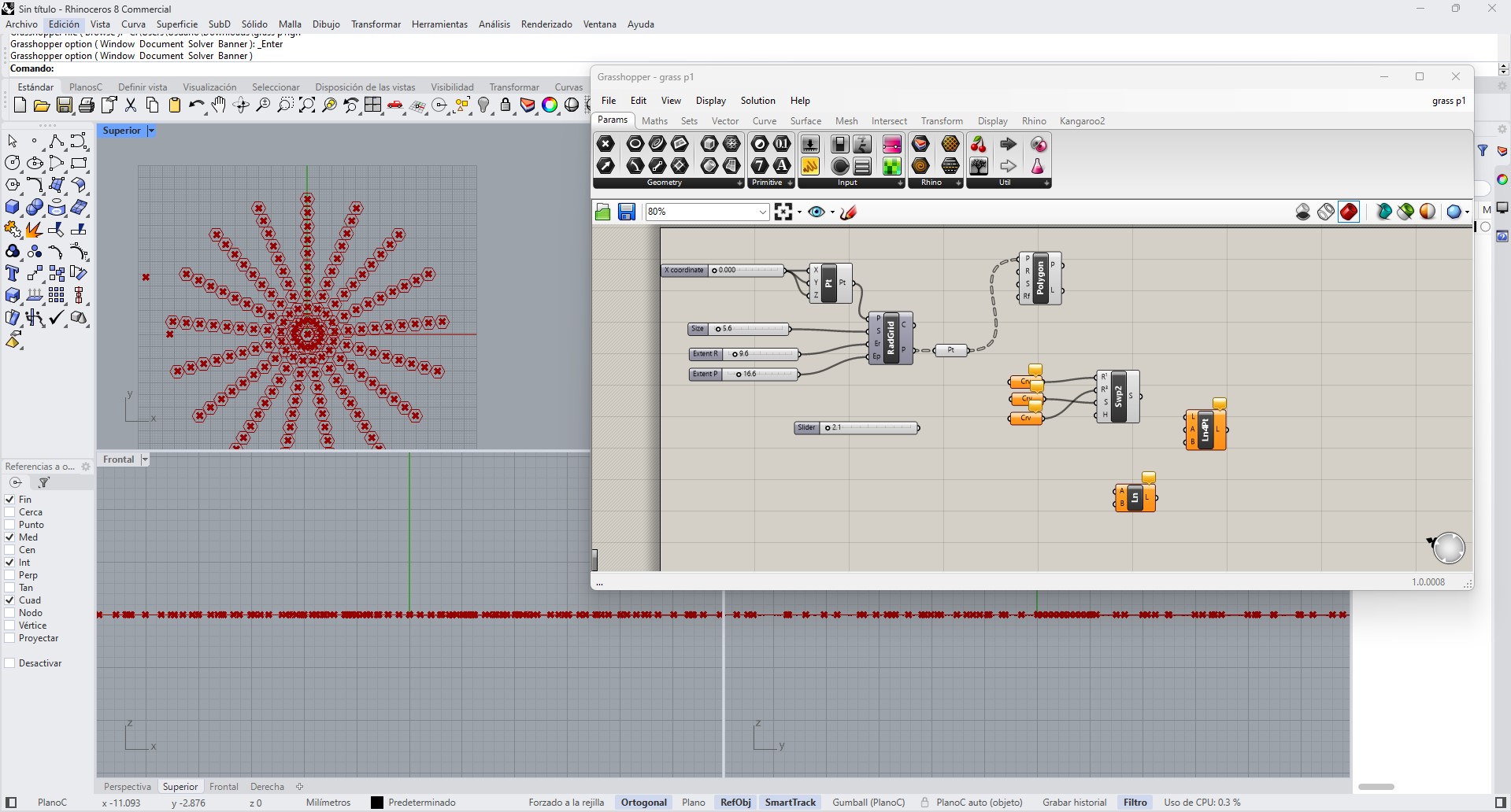
As part of the parametric design exercise, I explored the use of Grasshopper for Rhino to generate parametric geometries. Grasshopper is a visual programming environment that allows designers to create algorithmic models by connecting components that control geometry and parameters.
In this experiment, I tested a parametric definition that generated radial patterns using points distributed from a central coordinate system. By adjusting parameters such as radius, spacing, and the number of elements, the pattern could change dynamically.
Although I was able to generate different variations of the pattern, the final result did not fully work as expected and the geometry was difficult to control. This experiment helped me understand the basic logic of parametric workflows, including how parameters influence geometry and how visual programming can be used to explore design variations.
Even though the final geometry was not used in the fabrication process, this exercise was useful to better understand the potential of parametric design tools such as Grasshopper.
Download Files
The design files used in this assignment can be downloaded below.
Reflection
This week provided insight into how an idea evolves from hand sketching to a digital model prepared for fabrication and visualization. Iteration was essential to move from rigid geometries toward more expressive organic forms.