
Final Development of Design
The final design is an interactive kinetic flower developed as a circular modular object. The structure combines a central mechanism with a set of 3D printed petals distributed around the base, creating a composition that relates digital fabrication with organic movement and visual expression.
The design is organized around a circular base that contains the electronic and mechanical components. On the upper surface, multiple petals are arranged radially, generating a flower-like pattern. This layout was chosen to create a balanced visual composition and to reinforce the organic character of the project.
At the center of the system, a mechanical actuation mechanism controls the movement of the main petal or flower element. The objective of this mechanism is to allow the piece to open and close in response to interaction, connecting the physical form of the object with sensor-based behavior.
The project integrates several Fab Academy processes, including 2D and 3D design, additive fabrication, electronics, embedded programming, and system integration. The result is not only a decorative object, but an interactive system that responds to its environment through movement.
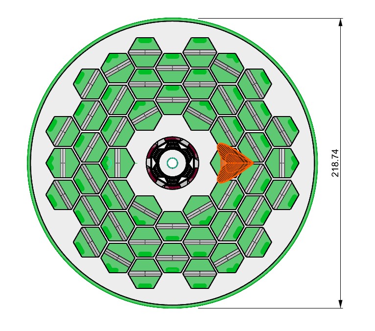
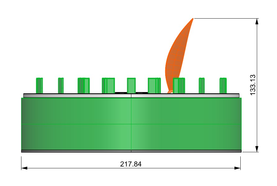
A. Overall Dimensions
The following section presents the general dimensions of the product, which define its overall scale and spatial configuration. These measurements were determined to ensure proper integration of the mechanical components, electronic system, and structural elements, while maintaining a compact and stable design.
B. Component Structure and Function
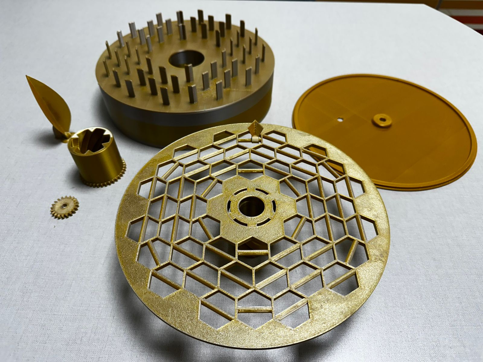
After defining the overall dimensions of the product, the system can be understood through its individual components. Each element was designed to fulfill a specific function within the structure, contributing to the integration of the mechanical, electronic, and aesthetic aspects of the project.
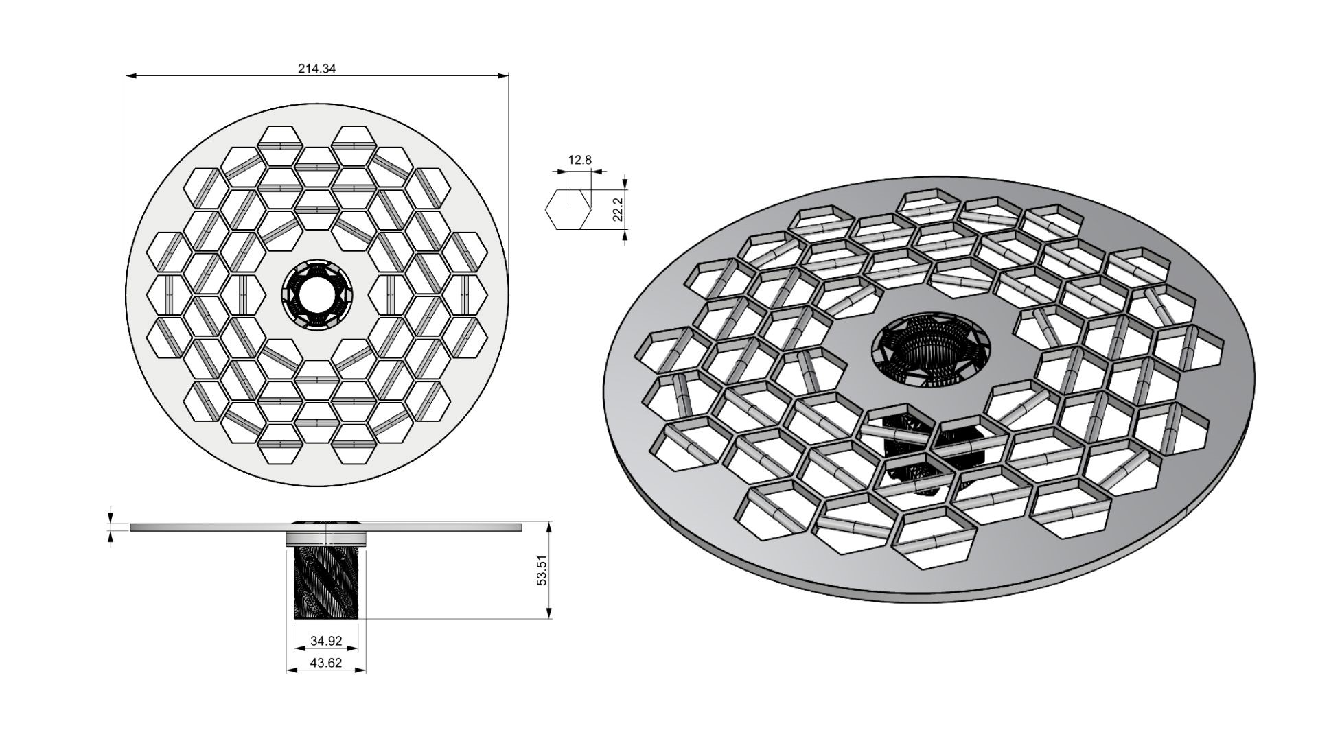
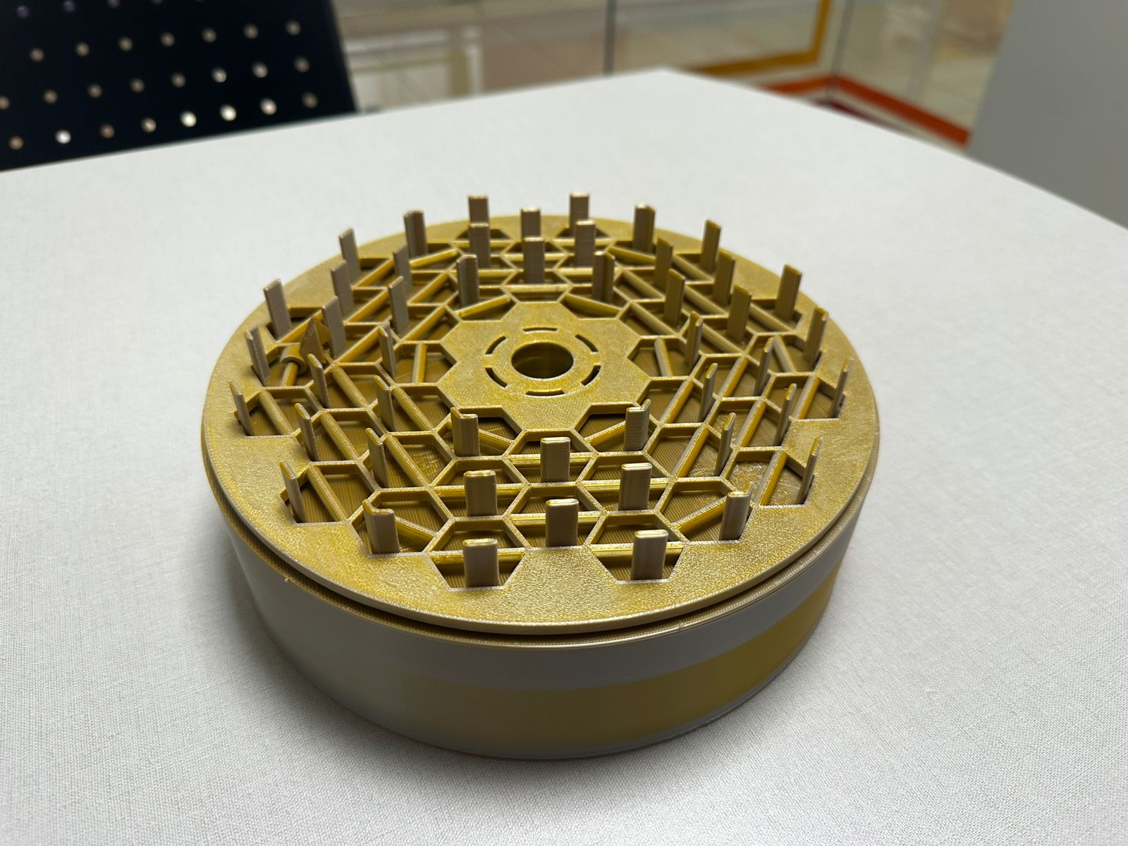
Hexagonal Support Structure
This image shows the petal support system based on a radial hexagonal pattern. The geometry was designed to distribute the anchoring points evenly and support a controlled movement of the whole structure.
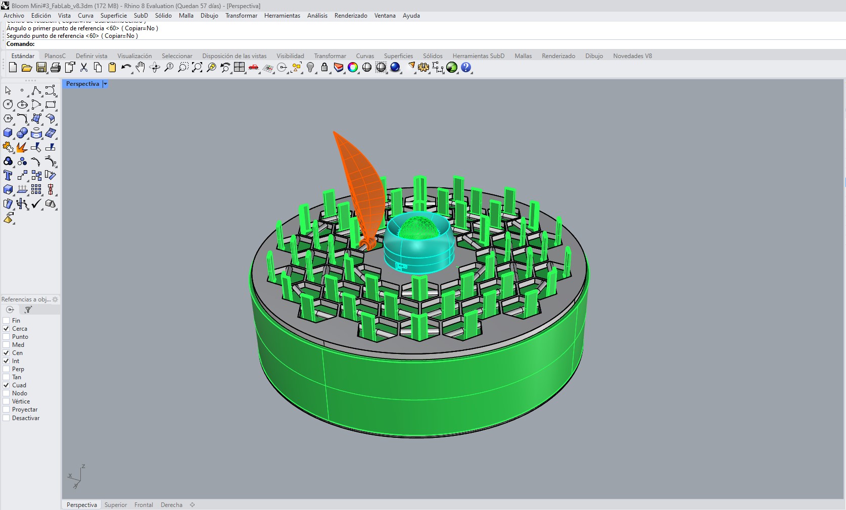
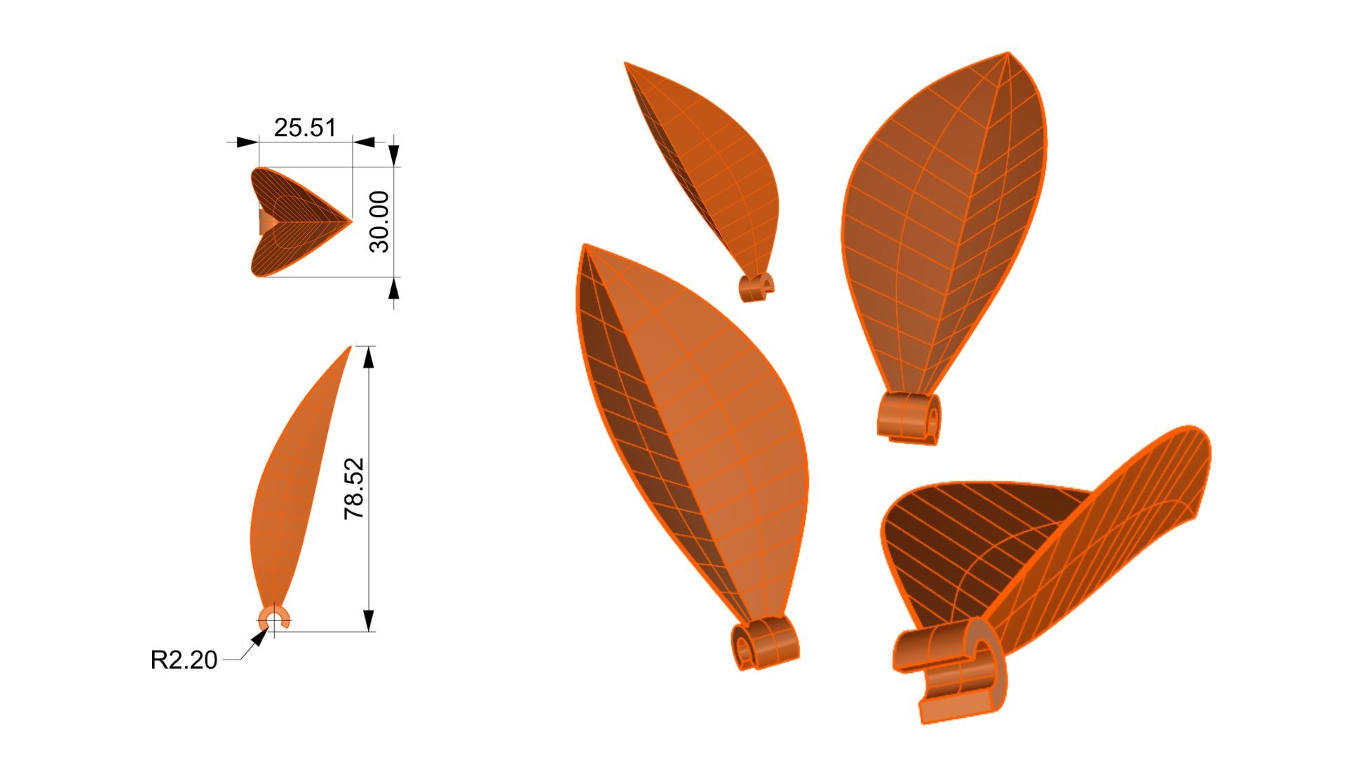
Petal Design
This image shows the petal as an independent component, with defined dimensions for 3D printing and later heat-forming. This process allows the petals to obtain a more organic shape during the physical fabrication stage.
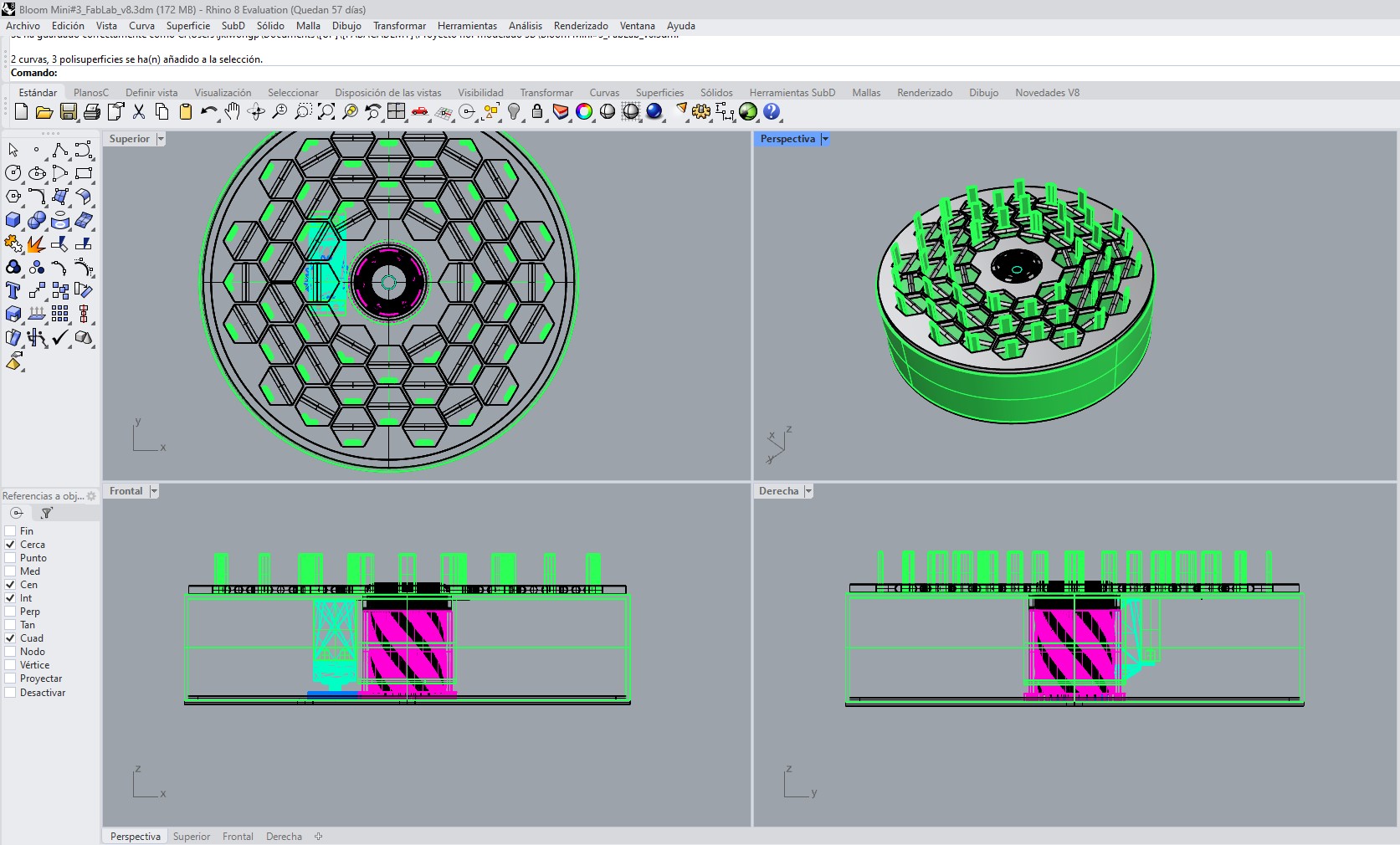
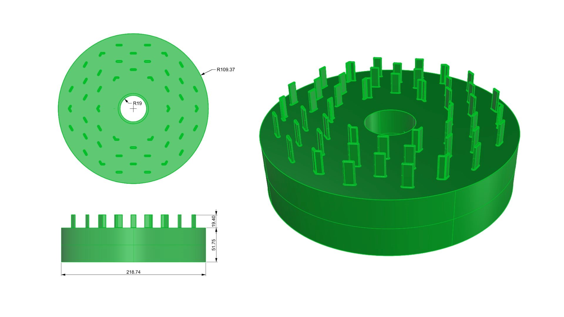
Base with Vertical Supports
This image shows the structural base with vertical elements that work as guides and fixing points for the petals, helping to ensure stability and repeatability during assembly.
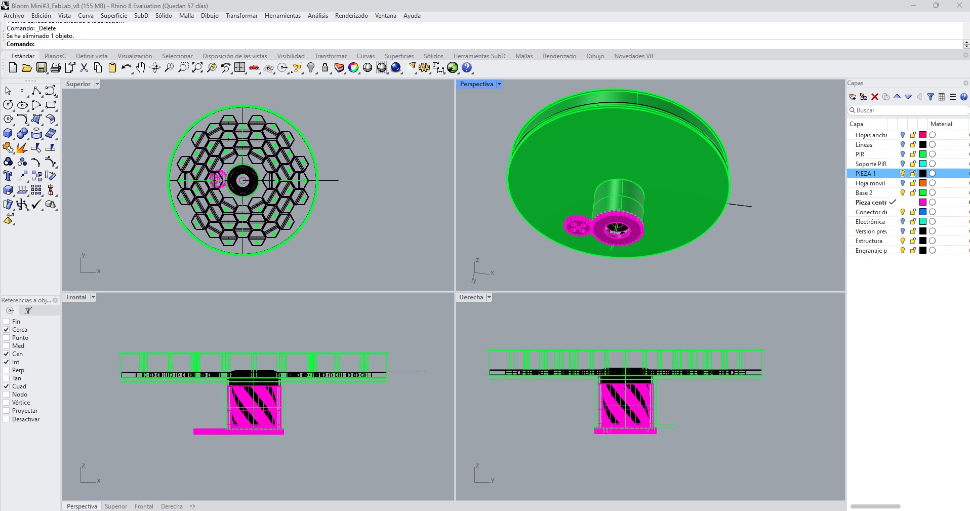
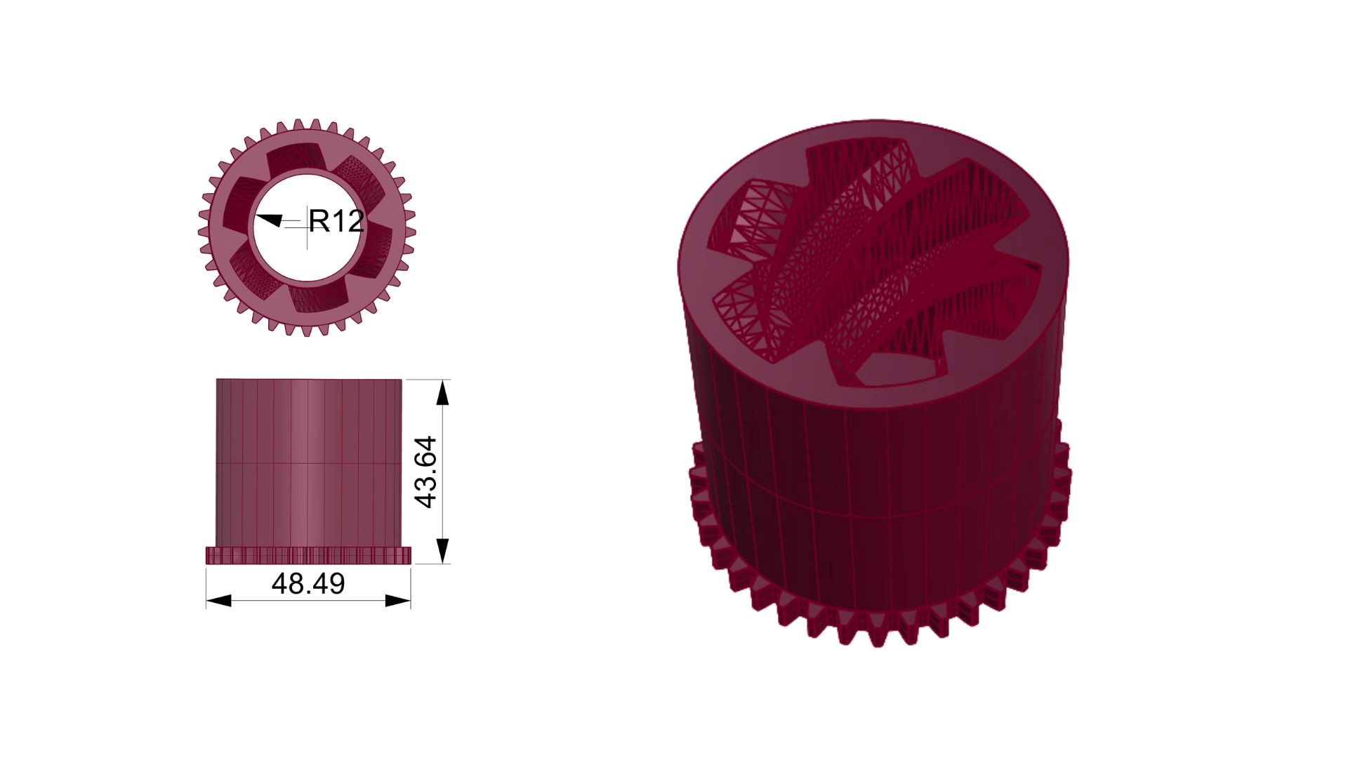
Central Coupling Mechanism
This image shows the central component responsible for transmitting the servo movement to the mechanical system, integrating the coupling geometry needed to convert the actuator motion.
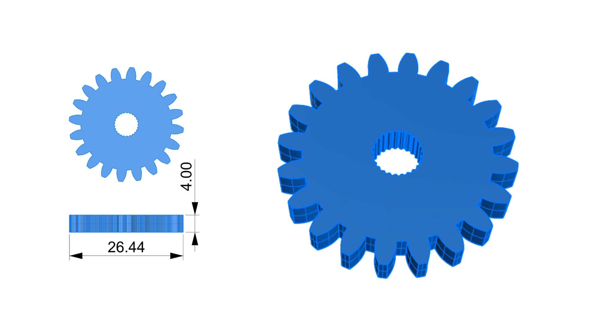
Gear Design
This image shows the gear designed for motion transmission within the system, with a geometry adapted to the central mechanism and the actuator coupling requirements.
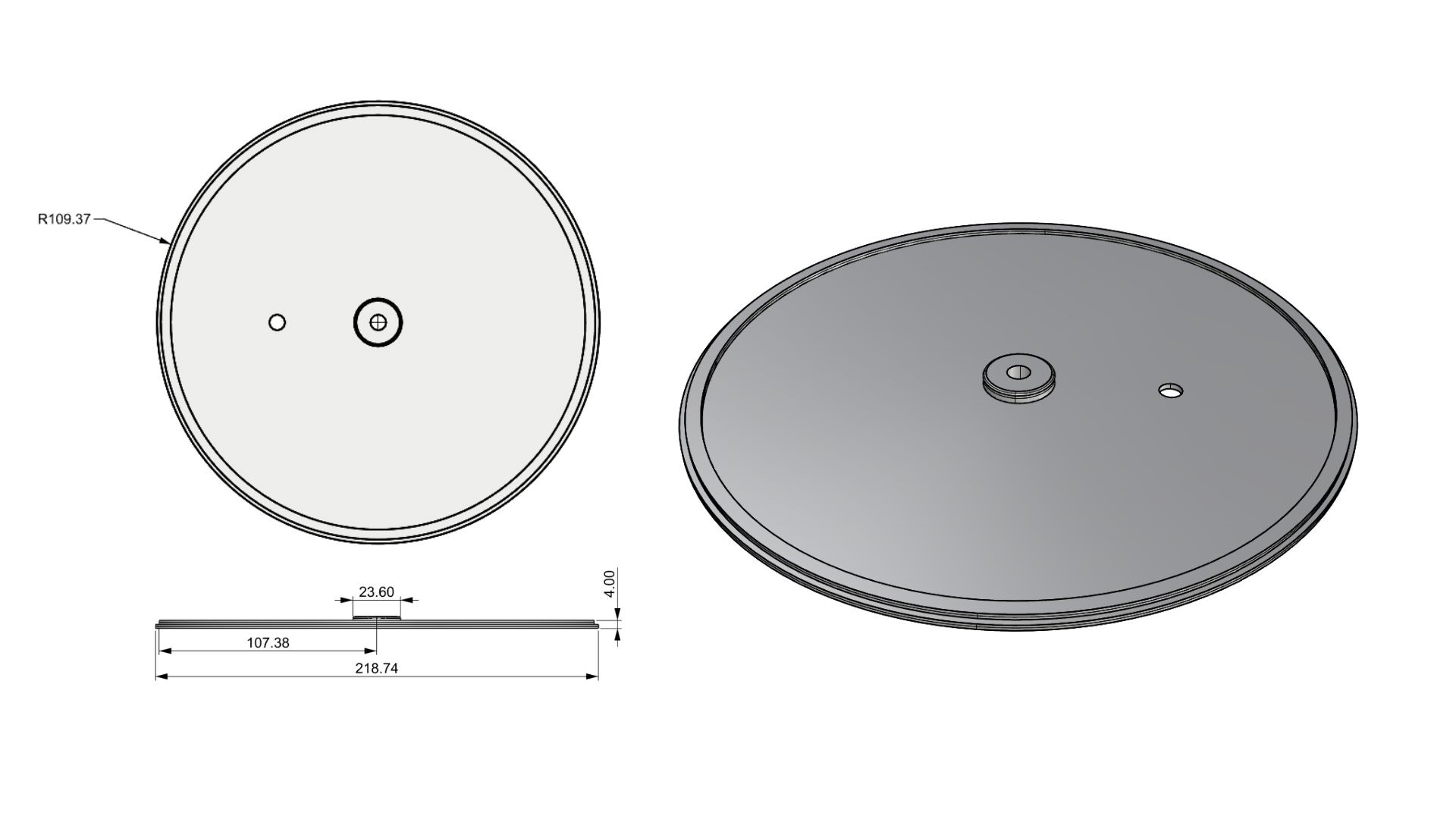
Bottom Cover
This image shows the bottom cover of the system, designed to close the structure, support the assembly, and provide space for integrating the electronic components.
C.Fabrication – 3D Printing
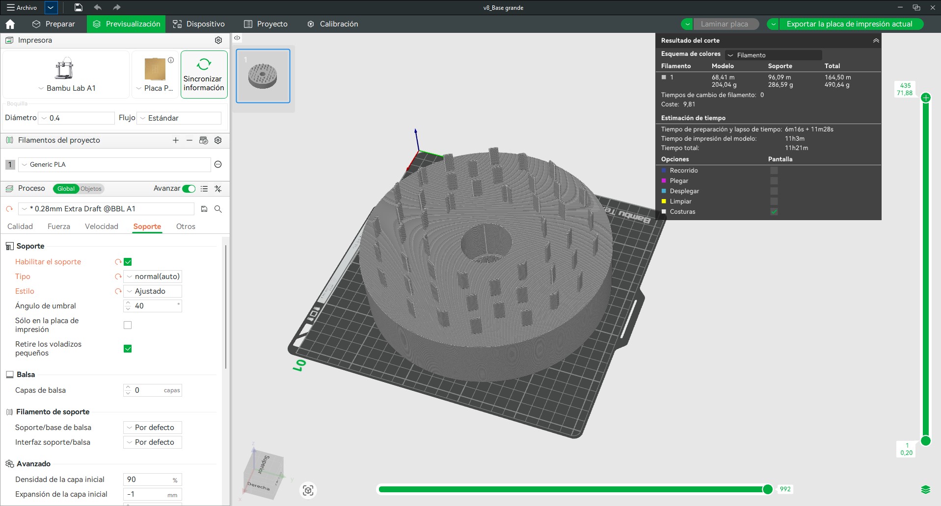
After completing the 3D modeling phase, the components of the system were fabricated using FDM 3D printing. This process was selected due to its accessibility, speed, and suitability for producing complex geometries such as the petal supports and mechanical components.
Printing Strategy
The system was divided into multiple parts for fabrication: base structure, petal supports, petals, central mechanism, and gear. Each component was optimized individually to ensure print quality, reduce material usage, and avoid unnecessary supports.
- The base and structural components were printed flat to ensure stability and dimensional accuracy.
- The petals were printed in a vertical orientation to maintain their intended geometry and avoid deformation during printing.
- The gear and central mechanism were printed with higher precision settings to ensure proper fit and smooth motion.
Printing Parameters
The following parameters were used during the printing process:
- Material: PLA
- Layer height: 0.12 mm - 0.28 mm
- Infill: 15–20%
- Supports: not required in most of the parts (geometry optimized to avoid overhangs)
- Wall detection: thin walls enabled
Each print batch included multiple components arranged on the build plate to optimize time and material usage. On average, each batch required approximately 2 -4 hours of printing time.
D. Post-processing
After printing, the petals will be subject to a heat-forming process to achieve a more organic and curved shape. This step is critical, as the final geometry of the petals is not fully defined in the digital model but is achieved physically.
Minor cleaning and finishing operations were performed to remove imperfections and ensure proper assembly between components.
E. Assembly Considerations
During fabrication, tolerances were considered to ensure that all components fit correctly without excessive friction. Test fittings were performed to verify the alignment between the base, central mechanism, and gear system.
This phase marks the transition from digital design to physical validation, allowing the evaluation of structural stability, mechanical performance, and integration with the electronic system.
5. Electronics Development
The electronic system of the final project is based on the work developed in the previus weeks, where I tested the interaction between a PIR sensor, a servo motor, an LED indicator, and the XIAO ESP32-C3 microcontroller. This previous exercise was important because it allowed me to validate the basic logic that will later be integrated into the kinetic flower.
The objective of the electronic system is to allow the flower to react to the presence of a person. When the PIR sensor detects movement, the microcontroller processes the signal and activates the servo motor. The servo is mechanically connected to the central mechanism, which controls the opening and closing movement of the petals.