
Week 15 — Interface and Application Programming
Group Assignment
During this group assignment, different software platforms and communication methods were explored to develop interfaces capable of interacting with embedded systems and microcontrollers.
The objective was to understand how graphical interfaces, mobile applications, and external software can communicate with hardware systems through serial, Bluetooth, and WiFi communication.
The activities developed included:
- Serial communication through graphical interfaces
- Real-time sensor monitoring
- Wireless mobile control
- Bluetooth communication
- WiFi-based interfaces
- Integration between software and embedded systems
1. Processing – LED Interface Control
Objective
The objective of this test was to develop a graphical interface using Processing to control a LED connected to the XIAO ESP32-C3 through serial communication.
This activity validated:
- Serial communication in real time
- Graphical user interaction
- Control of digital outputs through software
- Hardware and software integration
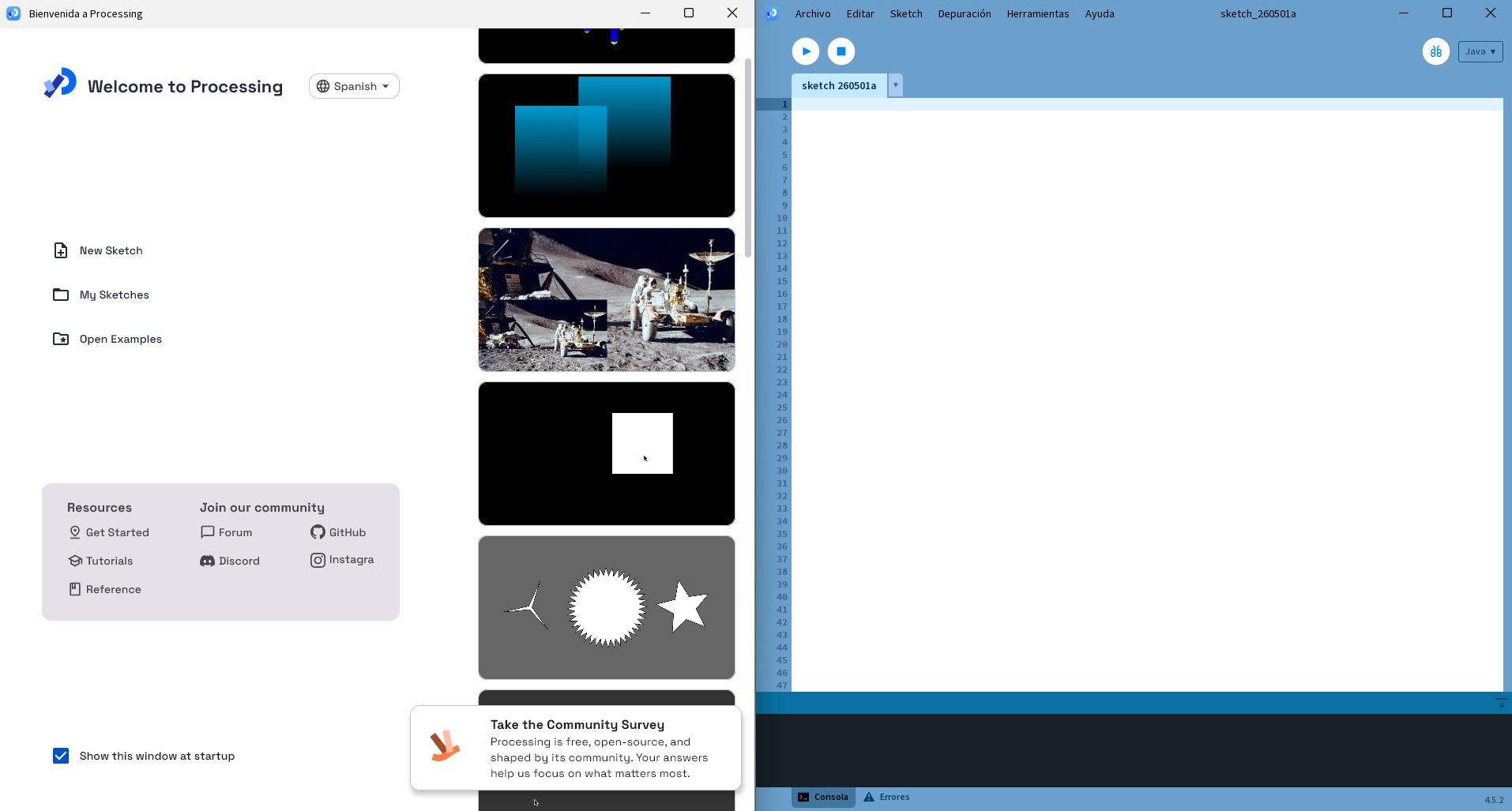
Initial Exploration of Processing
Before establishing communication with the microcontroller, several basic Processing sketches were developed to understand the structure and logic of the environment.
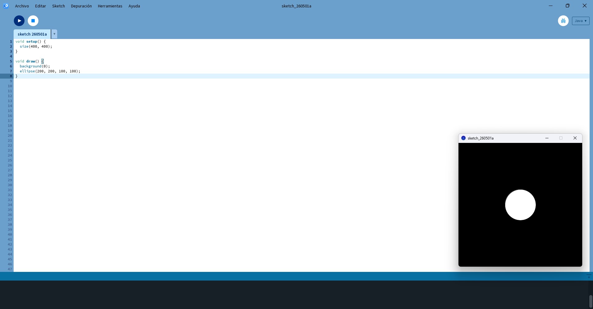
Two simple exercises were implemented:
- A static ellipse positioned at the center of the screen
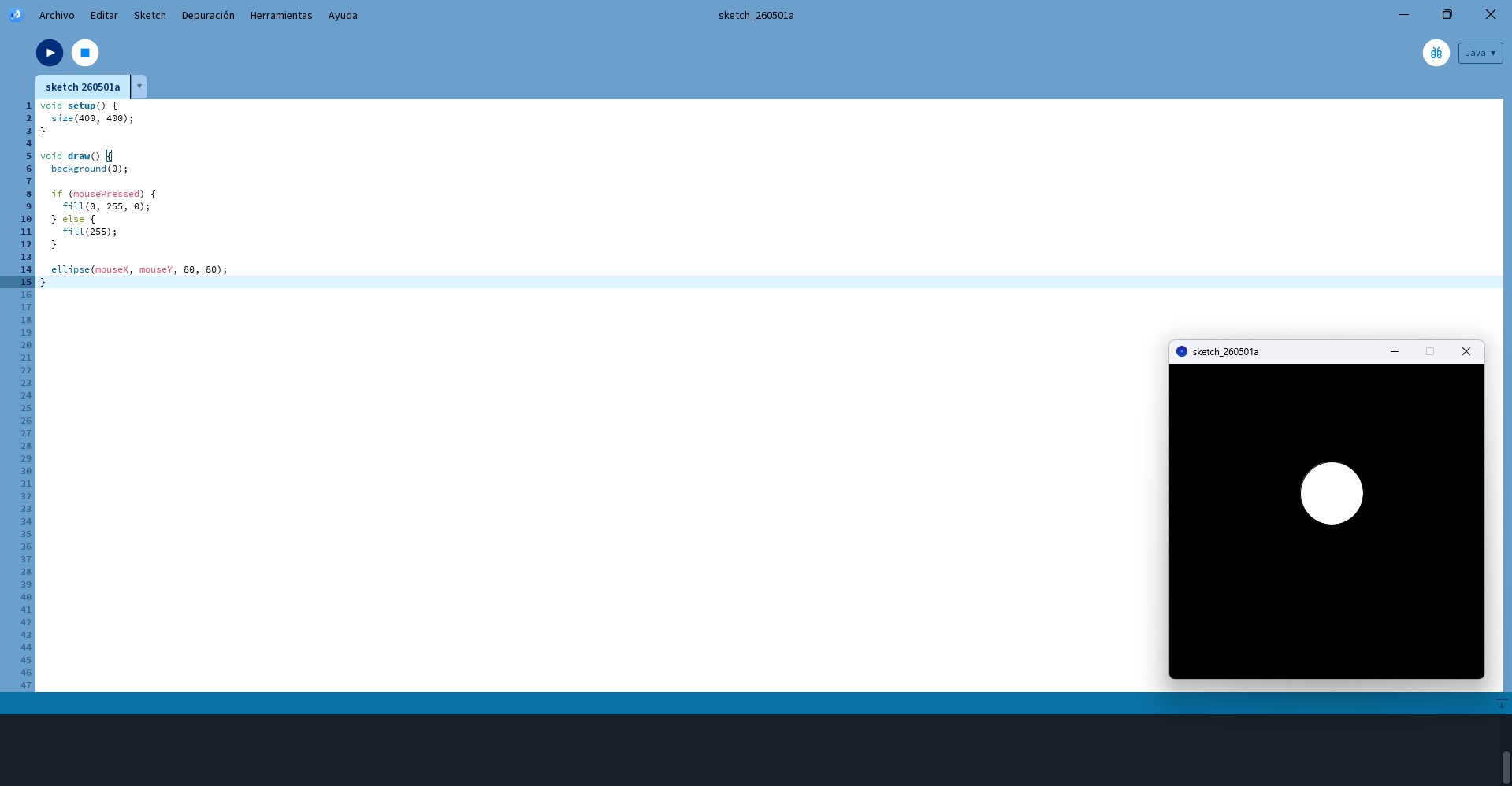
- An interactive version where the ellipse followed the mouse position
These exercises helped to understand:
- The structure of setup() and draw()
- Continuous rendering logic
- User interaction through mouse events
- Visual feedback systems
Hardware Configuration
The LED used during this test was integrated into the custom PCB and connected to pin D6 of the XIAO ESP32-C3.
A preliminary blinking test was performed to validate:
- Correct pin configuration
- Electrical functionality
- LED operation
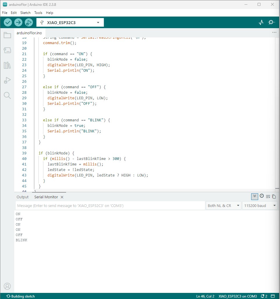
Arduino Code
The following Arduino code was uploaded to the XIAO ESP32-C3 to receive serial commands from Processing and control the LED behavior accordingly.
Verify Serial Communication
After uploading the code, serial communication was validated using the Arduino Serial Monitor.
- Open Serial Monitor
- Set baud rate to 115200
- Send the following commands:
The LED responded correctly to each command, validating both the serial communication and the embedded control logic.
Interface Development
A graphical interface was developed in Processing to control the LED through three operating modes:
- ON
- OFF
- BLINK
The interface communicated with the microcontroller using serial commands at 115200 baud.
The system included:
- Interactive buttons
- Status visualization
- Real-time communication
- Non-blocking blinking logic using millis()
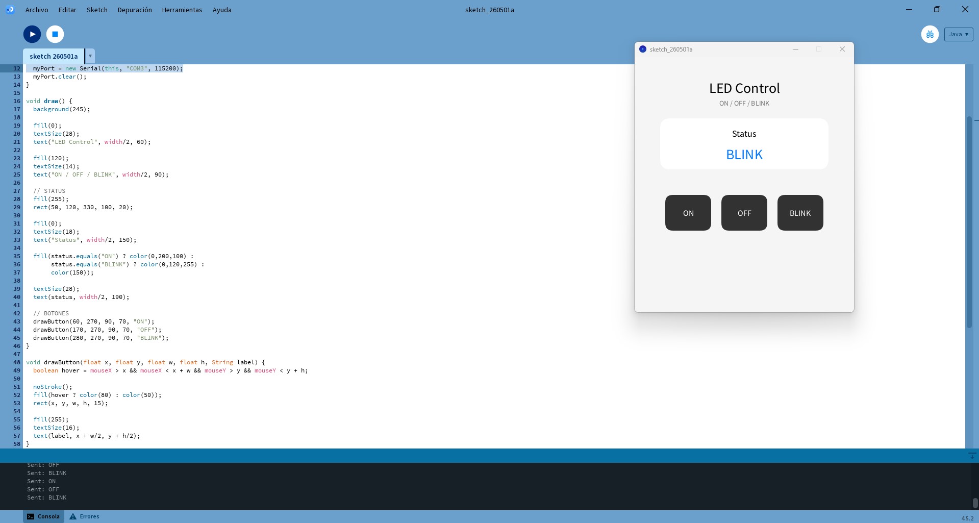
The interface successfully communicated with the microcontroller and allowed real-time LED control directly from the Processing application.
Results
The LED responded correctly to all commands sent from the graphical interface.
The test successfully demonstrated:
- Stable serial communication
- Real-time interaction
- Reliable LED control
- Integration between Processing and embedded hardware
Several issues were identified during testing:
- Serial port conflicts between Arduino IDE and Processing
- Incorrect assumption regarding the onboard LED
These problems were resolved by closing the Serial Monitor and using the external LED connected to D6.
2. PuTTY – Sensor Monitoring through Serial Communication
Objective
The objective of this exercise was to monitor data from an HC-SR04 ultrasonic sensor using serial communication and PuTTY software.
The activity allowed the understanding of:
- Serial communication workflows
- Real-time sensor monitoring
- External serial visualization tools
- Data transmission between hardware and software
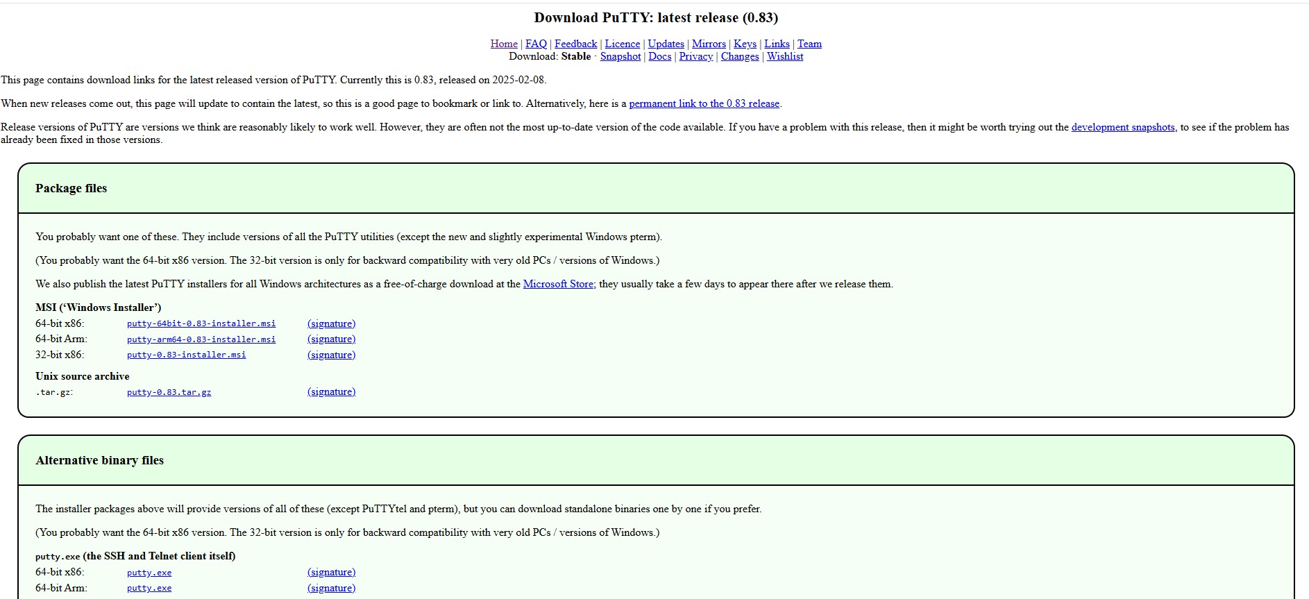
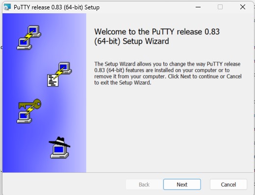
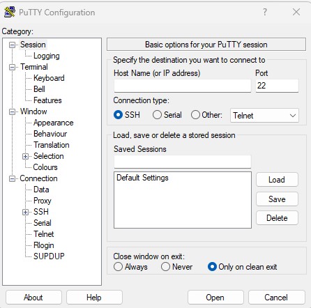
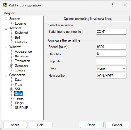
PuTTY Configuration
PuTTY was configured as a serial terminal interface using:
- Serial communication mode
- Correct COM port selection
- Baud rate configuration at 115200
Sensor Integration
The HC-SR04 sensor was connected to the microcontroller and programmed to:
- Trigger ultrasonic pulses
- Read echo response time
- Calculate distance values
- Send information through serial communication
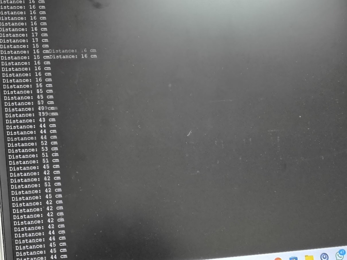
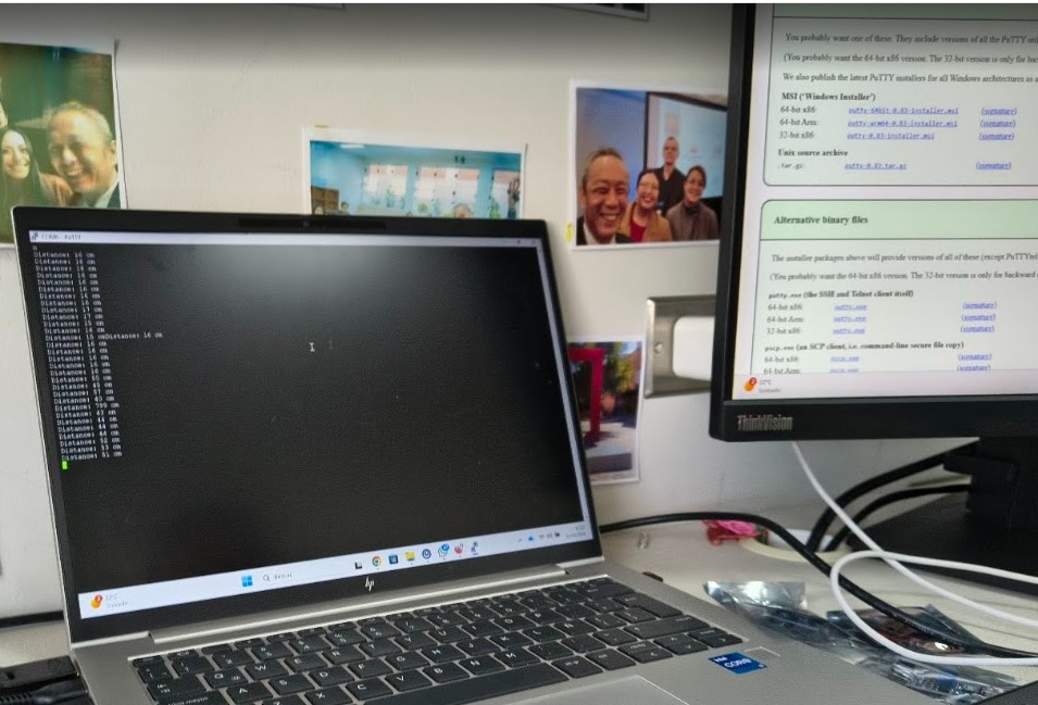
The measured distance values were displayed simultaneously in:
- Arduino Serial Monitor
- PuTTY serial terminal
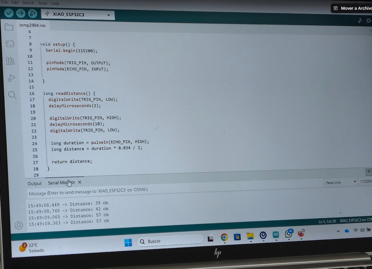
Arduino Code and Serial Monitor Output
The following Arduino code was used to read distance values from the HC-SR04 ultrasonic sensor and display the measurements through the Serial Monitor.
The Serial Monitor displayed the measured distance in centimeters and inches, allowing the sensor readings to be verified in real time.
Results
The test validated:
- Correct sensor reading
- Stable serial transmission
- Real-time data visualization
- Communication between hardware and external software
3. MIT App Inventor – Bluetooth Mobile Interface
Objective
The objective of this exercise was to develop a mobile application using MIT App Inventor to control an ESP32 through Bluetooth communication.
This activity explored:
- Wireless communication
- Mobile application development
- Visual block programming
- Bluetooth integration with embedded systems
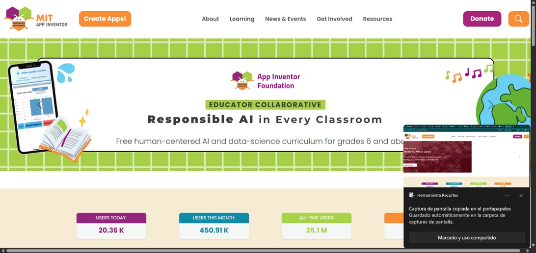
Introduction to MIT App Inventor
MIT App Inventor is a free visual programming platform that allows users to create mobile applications without traditional coding.
The platform works using drag-and-drop blocks, making it ideal for beginners and for rapid prototyping of interfaces capable of communicating with microcontrollers through Bluetooth or WiFi.
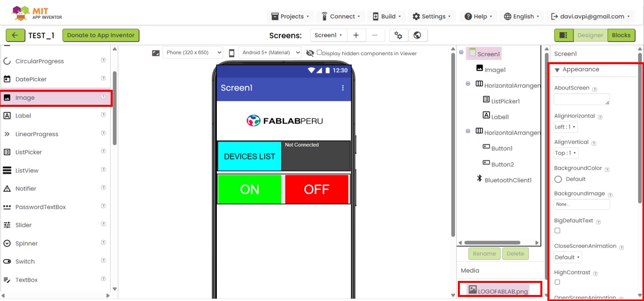
Project Configuration
A new project was created and configured using the “Advanced” settings.
Inside the Designer workspace, interface components were added using the Layout and User Interface menus.
The interface structure included:
- HorizontalArrangement containers
- ON and OFF buttons
- Bluetooth device selector (ListPicker)
- Text labels
- Custom images
Different appearance settings were adjusted, including:
- Button colors
- Container dimensions
- Alignment and spacing
- Image scaling
- Interface organization
Bluetooth Interface Logic
The application logic was developed in the “Blocks” environment.
The BluetoothClient component was added to establish communication with the ESP32.
The block:
BluetoothClient1.AddressesAndNames
was used to automatically retrieve paired Bluetooth devices, including both the MAC address and device name.
The ListPicker component was configured so that when pressed:
- The list of paired Bluetooth devices appears
- The user can select the ESP32 device
- The app attempts to establish a Bluetooth connection
A visual status message was added to indicate:
- Connected
- Not Connected
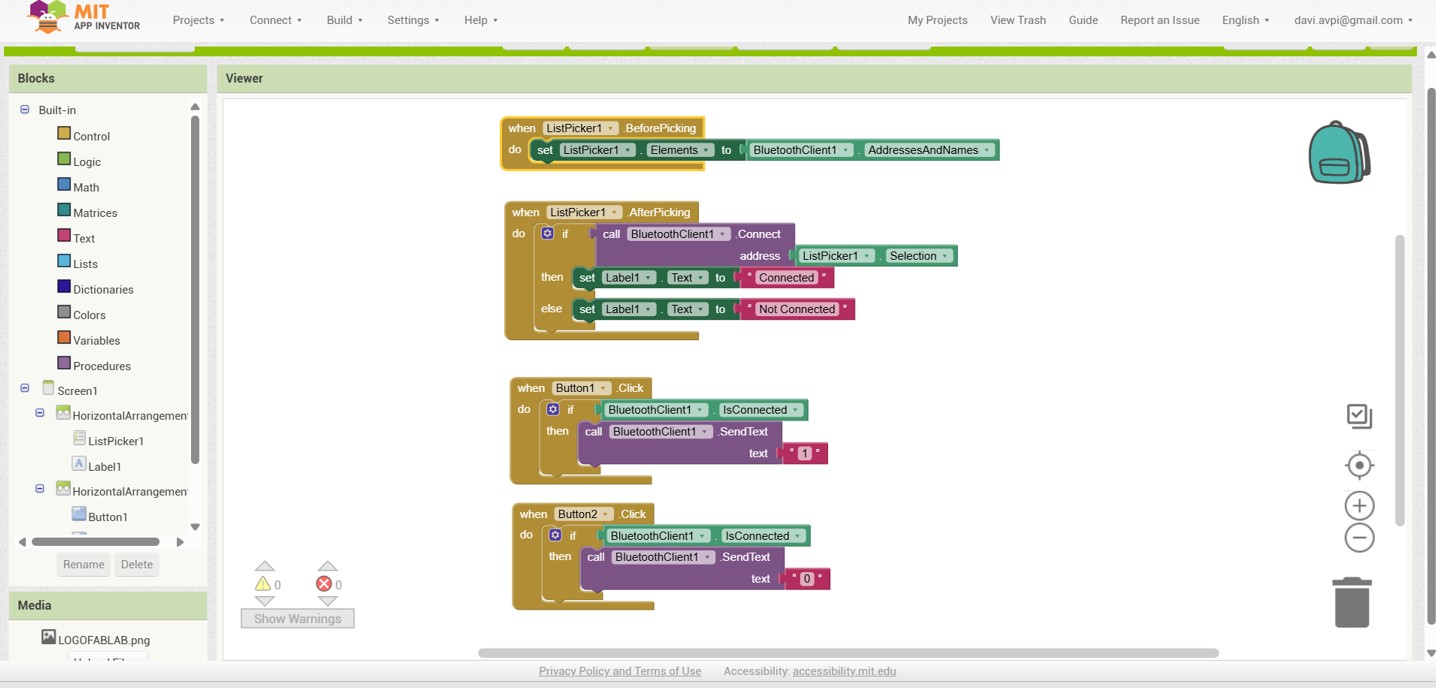
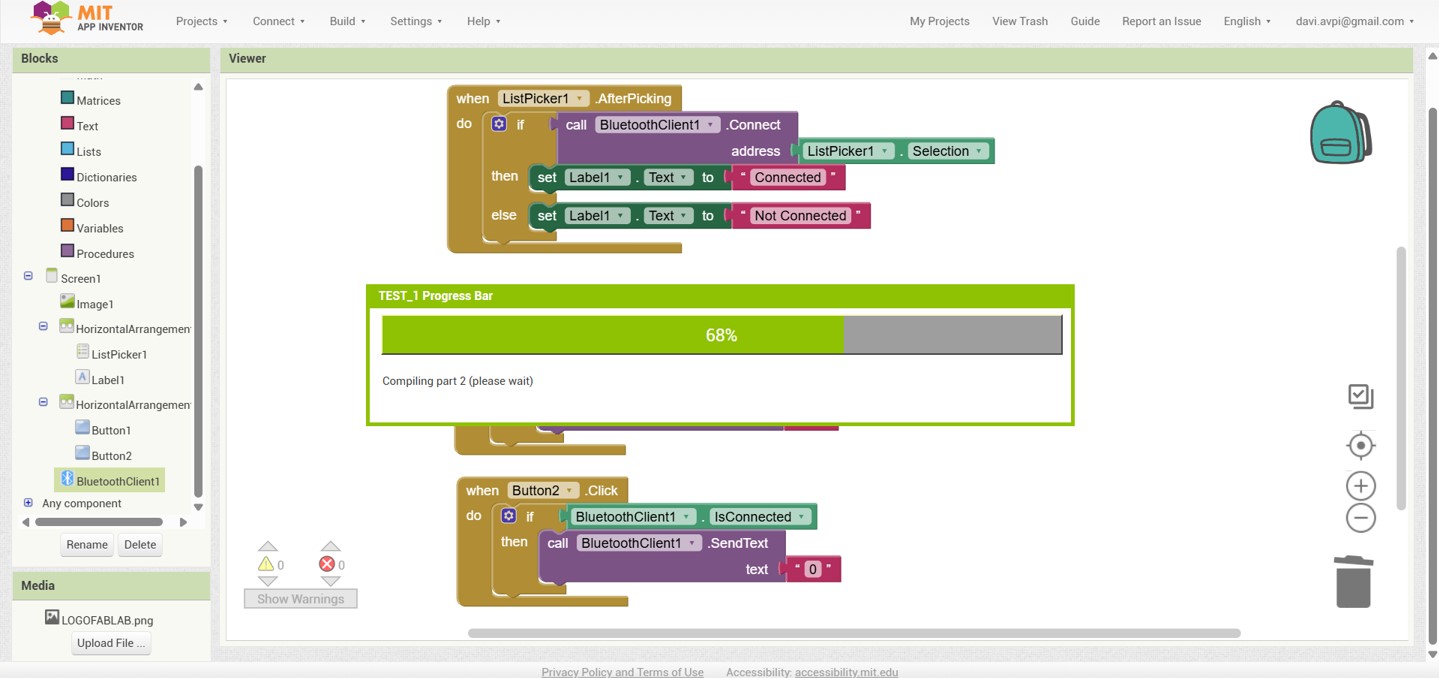
Control Logic
Once the Bluetooth connection was established, the ON and OFF buttons sent serial commands to the ESP32:
- "1" → LED ON
- "0" → LED OFF
This allowed wireless control of the embedded system directly from the mobile interface.
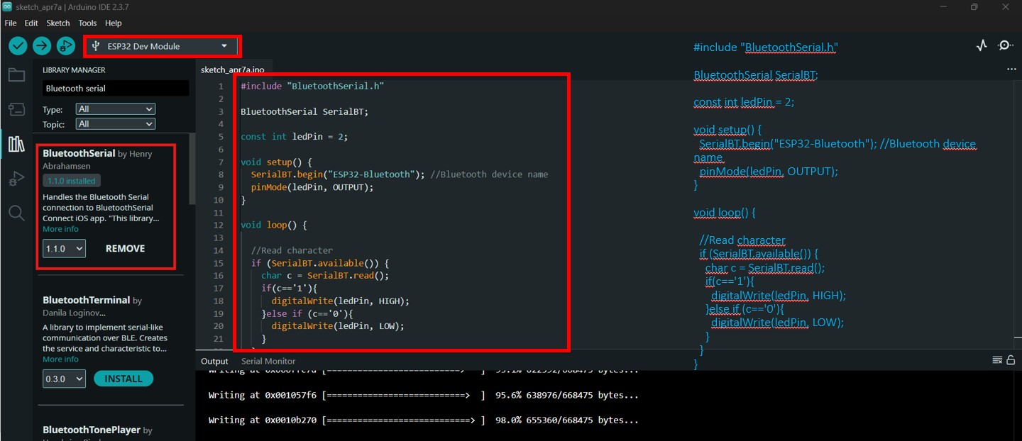
Arduino Code
The following Arduino code was uploaded to the ESP32 to receive Bluetooth commands from the mobile application.
Application Installation
After completing the application design, the APK file was generated using the “Build” option inside MIT App Inventor.
The APK was installed on an Android device for testing.
The ESP32 was paired through Bluetooth and selected from the “Devices List” inside the application.
Results
The application successfully demonstrated:
- Bluetooth communication between smartphone and ESP32
- Wireless LED control
- Real-time interaction
- Mobile interface integration with embedded hardware
The exercise validated the use of MIT App Inventor as a simple and effective platform for developing wireless mobile interfaces for embedded systems and IoT applications.
4. RemoteXY – Wireless IoT Interface
Objective
The objective of this exercise was to develop a wireless interface using RemoteXY to control a XIAO ESP32-C3 system through WiFi communication.
This activity explored:
- Wireless IoT communication
- Mobile interface development
- Real-time interaction
- Integration between hardware and software systems
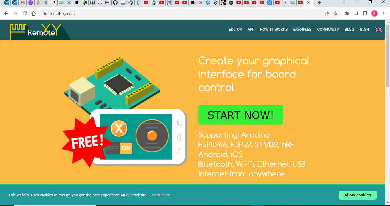
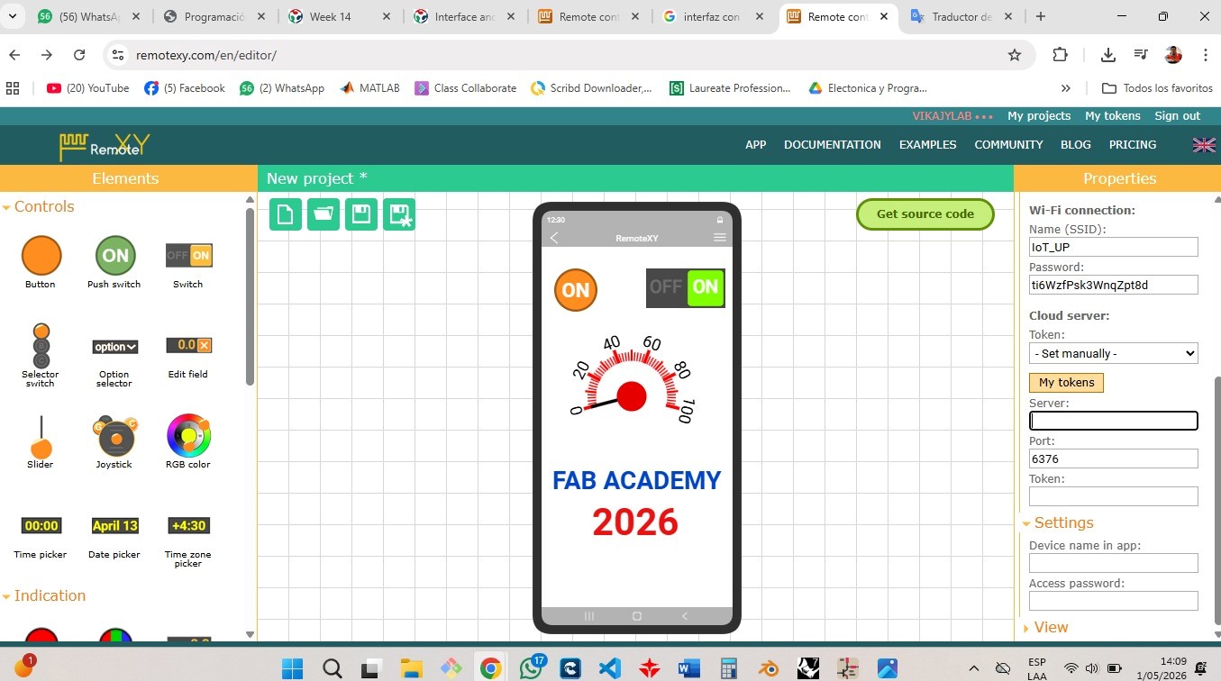
Tool Selection and Configuration
RemoteXY was selected because it allows the creation of professional graphical interfaces using a visual editor while automatically generating the communication code required for the embedded system.
The RemoteXY web editor was accessed through:
https://remotexy.com/en/editor/
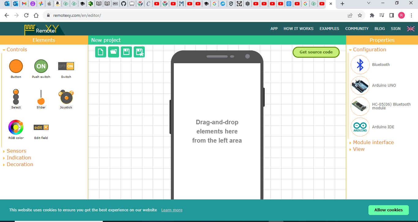
Project Configuration
Inside the “Properties” panel, the communication parameters between the interface and the hardware were configured.
The following settings were defined:
- Connection Type → WiFi Access Point
- Board → XIAO ESP32-C3
- Communication Module → ESP8266 WiFi Module
- Baud Rate → 115200
- SSID → IoT_UP
- Password → Secure access password
This configuration established the wireless communication architecture between the mobile interface and the embedded hardware.
Interface Design
The interface was designed using graphical components available in the RemoteXY editor.
The following controls were integrated:
- Switch → ON/OFF control
- Button → Temporary activation
- Gauge → Analog data visualization
- Text Labels → System identification
The interface layout considered:
- Visual hierarchy
- Ease of use
- Centered distribution
- Fast readability
Each interface element was linked to internal variables generated automatically by RemoteXY.
Examples:
- Switch → switch_1
- Button → button_1
This allowed user actions to generate digital signals interpreted by the microcontroller.
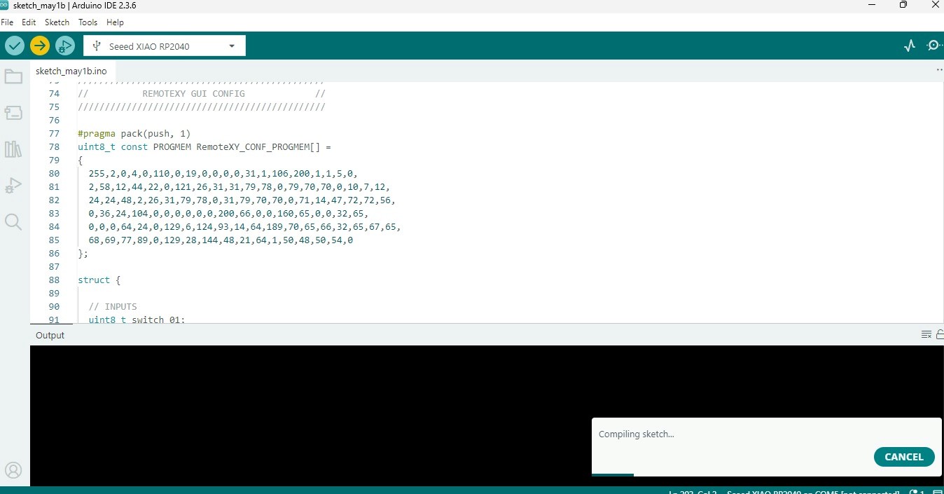
Automatic Code Generation
The “Get Source Code” function was used to automatically generate the communication code required for the project.
The generated code included:
- WiFi configuration
- Communication structure
- Synchronization functions
- Variable definitions
- RemoteXY initialization functions
The generated source code was then exported to Arduino IDE for implementation.
Programming and Implementation
The project was programmed using Arduino IDE and adapted to the XIAO ESP32-C3 board.
Environment Preparation
- Installation of the RemoteXY library
- Selection of the XIAO ESP32-C3 board
- COM port configuration
System Integration
The generated RemoteXY code was integrated into the project, including:
- RemoteXY_Init()
- RemoteXY_Handler()
- Pin definitions
- Communication management
Control Logic
The implemented logic allowed:
- Reading interface variables
- Digital output activation
- Real-time synchronization
Functional examples:
- Switch ON → LED activated
- Button pressed → Temporary activation
This validated bidirectional interaction between the interface and the hardware system.
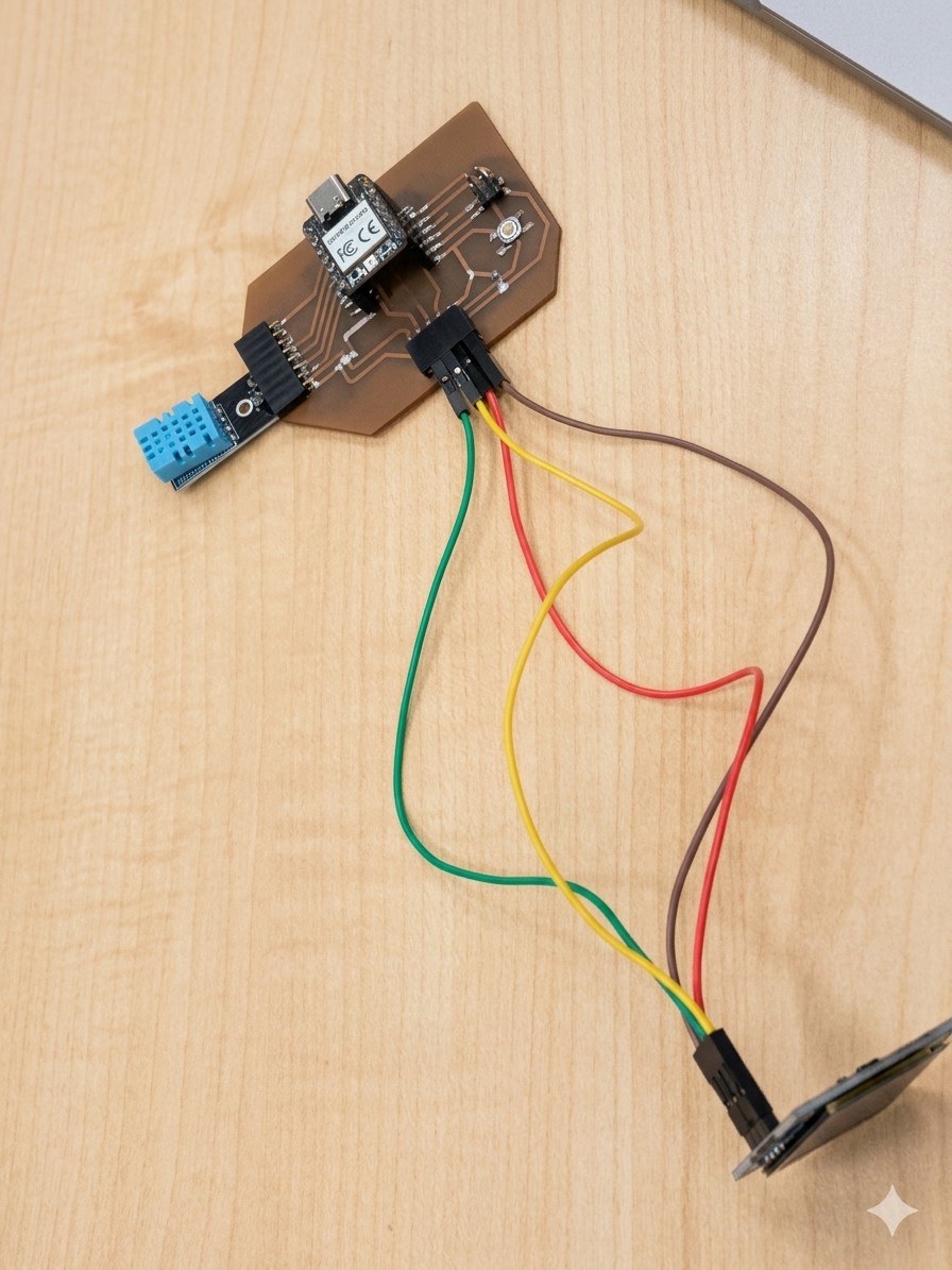
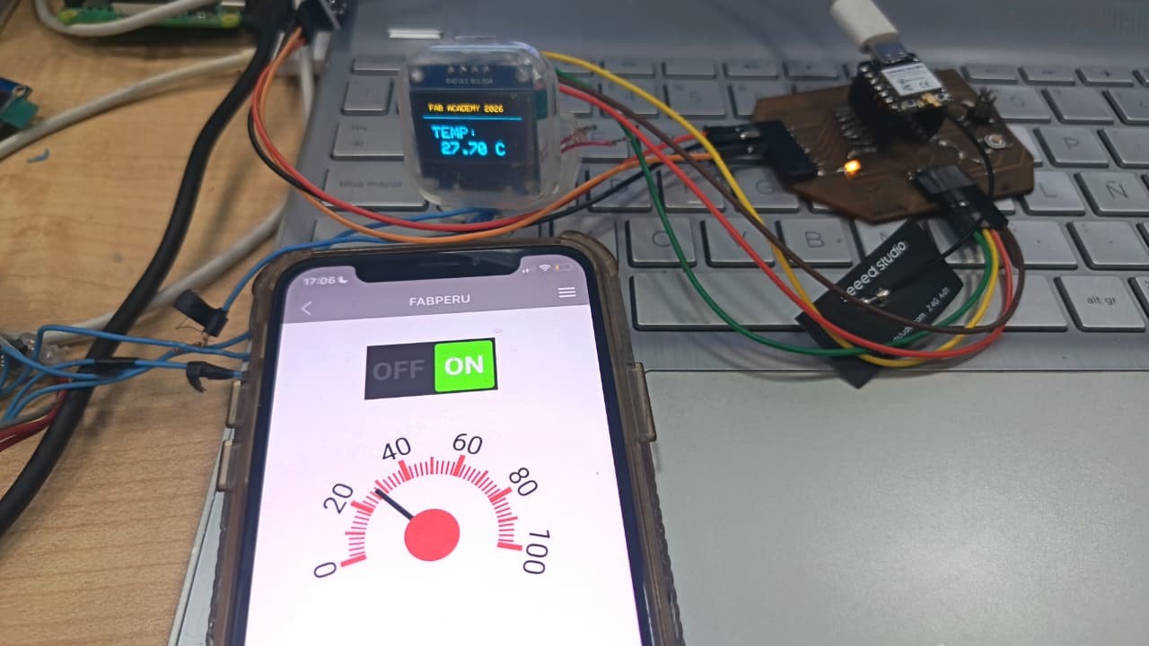
Physical Integration
The system integrated:
- XIAO ESP32-C3 as the main microcontroller
- ESP8266-01 for WiFi communication
- OLED display for real-time visualization
- Sensors and actuators for physical interaction
The ESP8266 communicated with the XIAO ESP32-C3 through serial communication (TX/RX connection) and was powered at 3.3V due to its voltage sensitivity.
The OLED display was connected through I2C communication, enabling real-time data visualization and integration between wireless communication, embedded control, and physical outputs.
Communication Flow
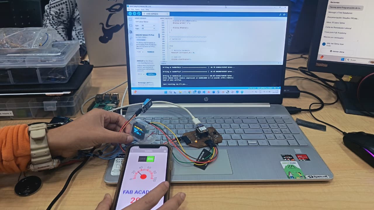
Results
The final system successfully demonstrated:
- Wireless communication between mobile interface and hardware
- Real-time system control
- OLED data visualization
- Bidirectional communication
- Integration between digital and physical interfaces
The exercise validated RemoteXY as an effective platform for developing IoT interfaces and wireless embedded system interactions.
Platform Comparison
| Platform | Communication Type | Main Function | Advantages | Limitations |
|---|---|---|---|---|
| Processing | Serial Communication (USB) | Desktop graphical interface for LED control | Real-time interaction, customizable interface, easy visualization | Requires wired connection and serial port availability |
| PuTTY | Serial Communication (USB) | Sensor monitoring and serial data visualization | Simple setup, lightweight software, useful for debugging | No graphical interface or advanced interaction |
| MIT App Inventor | Bluetooth | Mobile application for wireless LED control | Easy mobile app development, wireless interaction, visual programming | Limited interface customization and Bluetooth range limitations |
| RemoteXY | WiFi + Serial | Wireless IoT interface and system control | Real-time wireless communication, professional UI generation, IoT integration | More complex configuration and dependency on network setup |
The comparison demonstrates how different software platforms can be used to establish communication between users and embedded systems depending on the required level of interaction, visualization, portability, and wireless connectivity.
Conclusions
The different exercises developed during this group assignment allowed the exploration of multiple methods of interaction between software interfaces and embedded systems.
Each platform provided a different approach:
- Processing → Desktop graphical interfaces
- PuTTY → Serial monitoring
- MIT App Inventor → Mobile Bluetooth interfaces
- RemoteXY → Wireless IoT interfaces
Together, the activities validated:
- Serial communication workflows
- Wireless interaction systems
- Hardware-software integration
- Real-time control systems
- Development of interactive interfaces
The exercises also demonstrated how different interface tools can be adapted according to the complexity, portability, and interaction requirements of embedded systems and digital fabrication projects.