
Week 06 — Observing Microcontroller Signals
Group Assignment
The objective of this group assignment was to use the electronic test equipment available in the laboratory to observe the operation of a microcontroller circuit board. In particular, we focused on understanding how digital signals behave when the microcontroller executes a program.
To perform this analysis, we used a logic analyzer, a tool that allows us to capture and visualize digital signals generated by electronic circuits. This instrument is commonly used to analyze communication protocols and timing behavior in embedded systems.
1. Test Equipment and Materials
During this activity we explored some of the electronic measurement tools available in the laboratory. These tools allow us to test, debug and analyze electronic circuits.
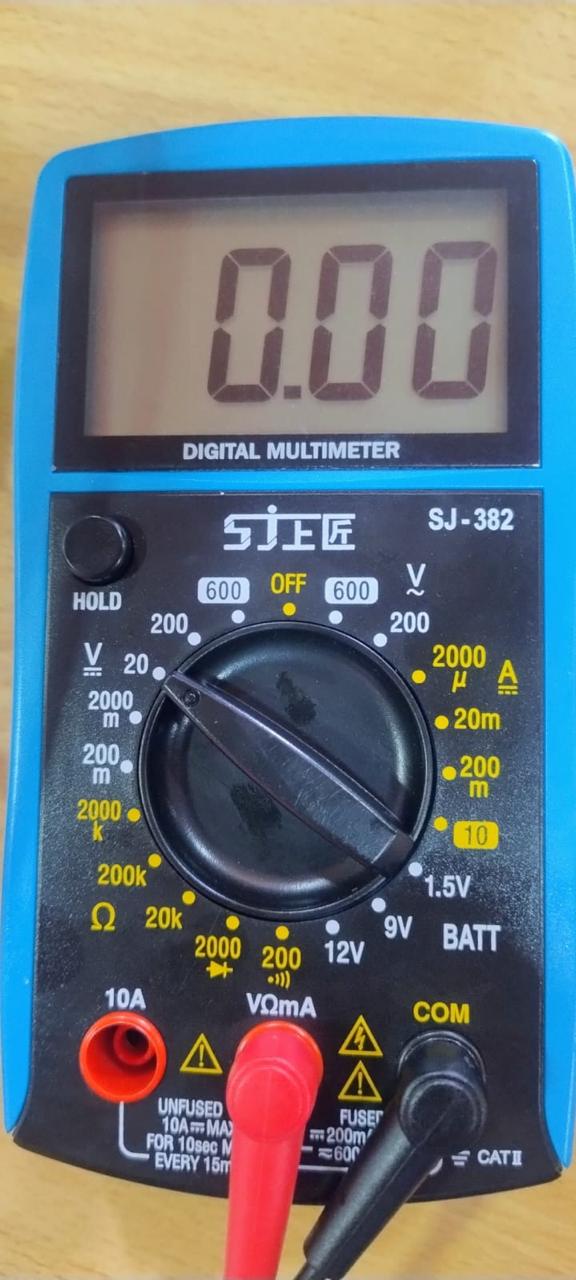
Digital Multimeter PR-75
Type: Portable digital multimeter. The PR-75 is a general-purpose handheld digital multimeter designed for basic electrical measurement tasks in electronics and electrical work.
Main features:
- DC / AC voltage measurement up to 600V
- Resistance measurement (Ω)
- Continuity test with buzzer
- Diode test
- Current measurement (mA and 10A)
- Digital LCD display
- Manual range selector
Practical use: Verify power supply (3.3V and 5V), check continuity between traces, and rule out short circuits before taking measurements with an oscilloscope.
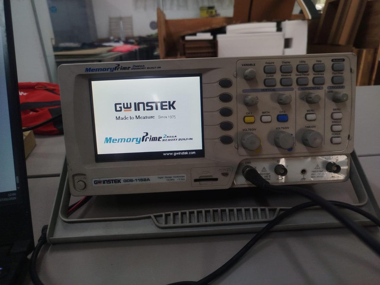
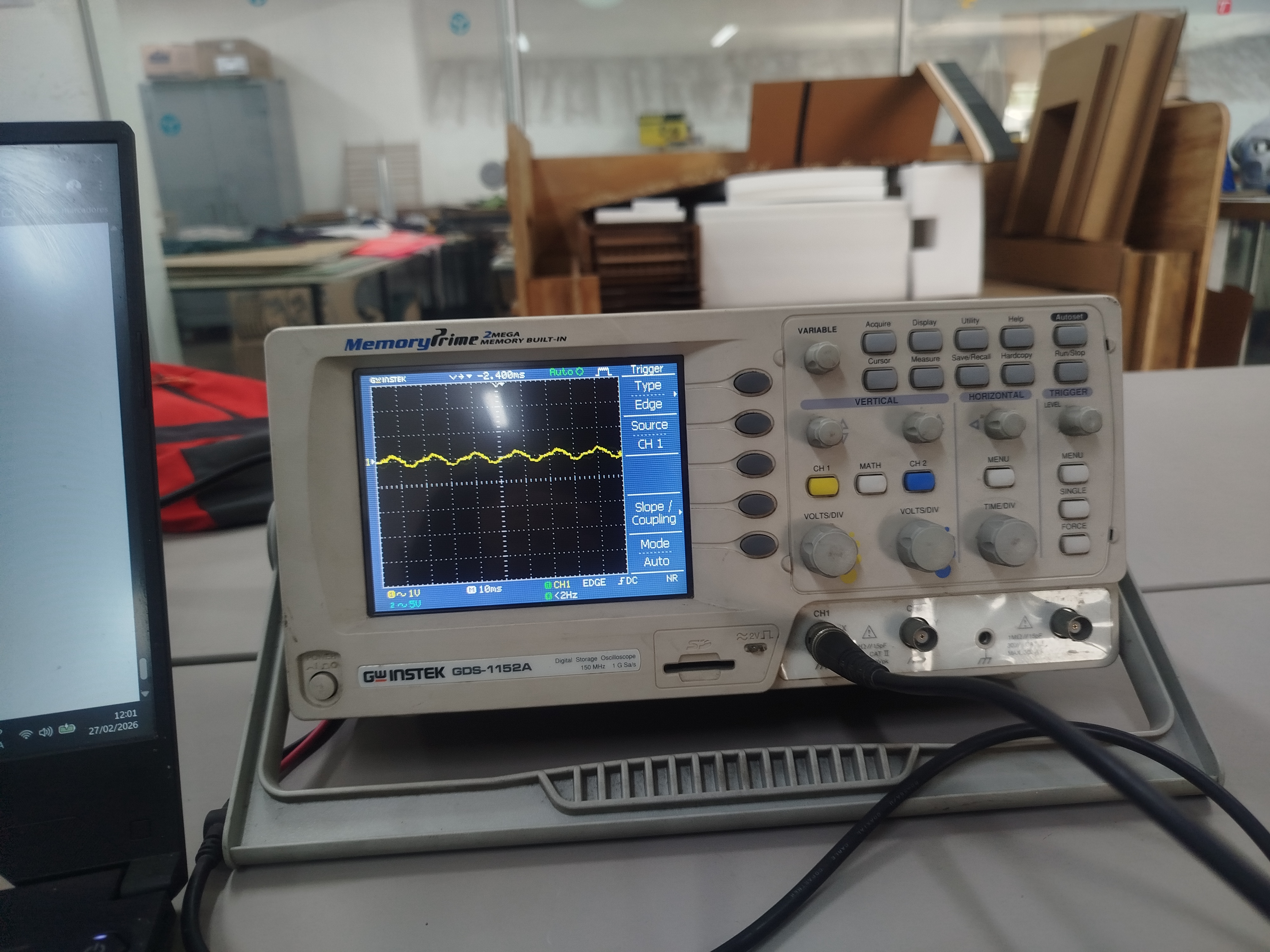
Digital Oscilloscope (GW Instek GDS-1152A)
Type: Two-channel digital oscilloscope (150 MHz, 2-channel model) for electronics labs. It captures and stores waveform data, letting you view, measure, and analyze electronic signals visually.
Main features:
- 2 channels (CH1 and CH2)
- Autoset function for quick signal adjustment
- VOLTS/DIV and TIME/DIV controls
- Trigger system for signal stabilization
- Waveform visualization
- Measurement of values such as voltage and frequency
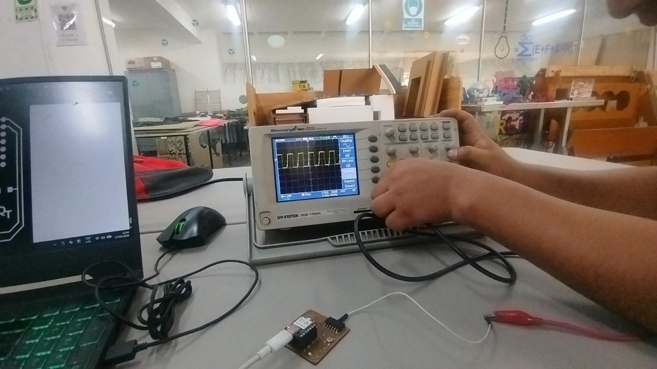
Practical use: Verify signals over time, such as a square wave or a PWM signal, and test the microcontroller’s output pin, digital signal behavior, and code execution through its pins.
Materials
- XIAO ESP32-C3 Seeed Studio Mini Development Board with WiFi and BLE
- Board
- Wires
- LEDs
- Buttons
- Resistors
2. Test Setup
First, a microcontroller development board was programmed with a simple test code designed to generate digital signals on specific pins. These signals allow us to observe how the microcontroller interacts with the circuit and verify the correct execution of the program.
The logic analyzer probes were then connected to the selected pins of the microcontroller board in order to capture the digital signals during operation.
3. Signal Capture
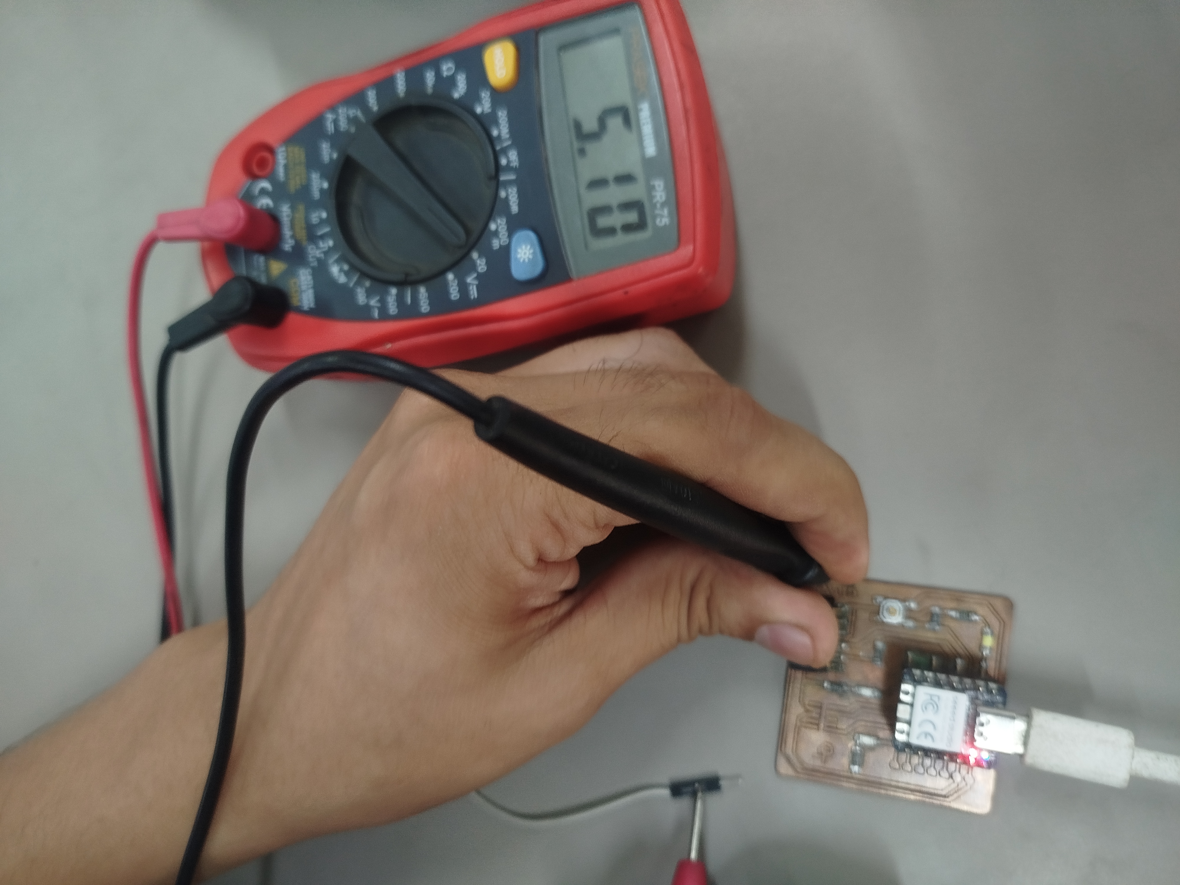
Multimeter Reference and Usage
The multimeter used during this activity was the PR-75 Portable Digital Multimeter. This device is used to measure electrical parameters such as voltage, resistance, and continuity, making it essential for validating circuits.
In this assignment, the multimeter was used to verify voltage levels, check electrical connections, and ensure that the circuit was functioning correctly.
Procedure
- Turn on the multimeter and select the appropriate measurement mode (DC Voltage, Resistance, or Continuity).
- Connect the black probe to the COM port and the red probe to the VΩ port.
- For voltage measurement, place the probes across the component or output pin and ground.
- For continuity testing, place the probes at both ends of a connection to verify if the circuit is closed.
- For resistance measurement, place the probes across the resistor to confirm its value.
- Read the values displayed on the screen and compare them with expected values.
Key Functions Used
- DC Voltage (V⎓): To measure signal levels
- Continuity Mode: To verify electrical connections
- Resistance (Ω): To check component values
References
- Fluke. How to Use a Digital Multimeter. https://www.fluke.com/en-us/learn/blog/digital-multimeters/how-to-use-a-digital-multimeter
Oscilloscope Reference and Usage
The oscilloscope used during this activity was the GW Instek GDS-1152A, a 150 MHz, 2-channel digital storage oscilloscope. This equipment allows real-time visualization of electrical signals, making it possible to analyze voltage variations over time.
In this assignment, the oscilloscope was used to observe digital signals generated by the microcontroller, allowing verification of signal transitions, stability, and timing behavior.
Procedure
- Connect the oscilloscope probe to the signal output pin of the microcontroller.
- Connect the ground clip of the probe to the circuit ground (GND).
- Turn on the oscilloscope and select the corresponding input channel (CH1).
- Adjust the voltage scale (Volt/div)< to match the expected signal amplitude (typically 3.3V or 5V).
- Adjust the time scale (Time/div) to visualize the signal clearly over time.
- Configure the trigger to stabilize the waveform on the screen.
- Observe the signal and verify changes in voltage corresponding to the sensor or input behavior.
Key Parameters
- Voltage scale (Volt/div): Defines signal amplitude visualization
- Time scale (Time/div): Defines how time is displayed
- Trigger: Stabilizes the waveform for consistent observation
References
- GW Instek. GDS-1000 Series Digital Storage Oscilloscope Datasheet. https://www.gwinstek.com/en-global/products/detail/GDS-1000
- Tektronix. XYZs of Oscilloscopes Primer. https://www.tek.com/en/documents/primer/xyzs-oscilloscopes-primer
4. Analysis
By observing the signal patterns captured by the logic analyzer, we were able to confirm that the microcontroller was correctly executing the programmed instructions. The captured waveform shows the changes in voltage levels corresponding to the digital output signals.
This type of analysis is essential for debugging electronic circuits and verifying communication between devices such as sensors, microcontrollers, and other digital components.
Conclusion
This activity allowed us to understand how electronic signals behave inside a microcontroller circuit and how diagnostic tools such as a logic analyzer can be used to monitor and analyze these signals. Learning to use these tools is fundamental for developing and troubleshooting embedded systems.