WEEK 17
Wildcard Week
- Design and produce something with a digital process (incorporating computer aided design and manufacturing) not covered in another assignment, documenting the requirements that your assignment meets, and including everything necessary to reproduce it. Possibilities include but are not limited to wildcard week examples.
Introduction
During Wildcard Week, the goal was to design and manufacture a project using a digital fabrication process not covered in previous assignments, integrating computer-aided design and digital manufacturing within a fully reproducible workflow. For this week, I chose to work with fiber laser cutting on metal and CNC bending, as these processes allowed me to explore high-precision sheet metal fabrication techniques, from designing the flat pattern in CAD to preparing the cut file and the bending sequence to transform a 2D geometry into a functional three-dimensional structure. I chose these machines because they represent an industrial manufacturing workflow different from those previously completed.
Development
Designing the FABLAB logo in sheet metal
For the sheet metal design, I wanted to extract the cube from the FABLAB logo, showing only its 3 visible faces, and from that design my sheet metal part in SolidWorks.

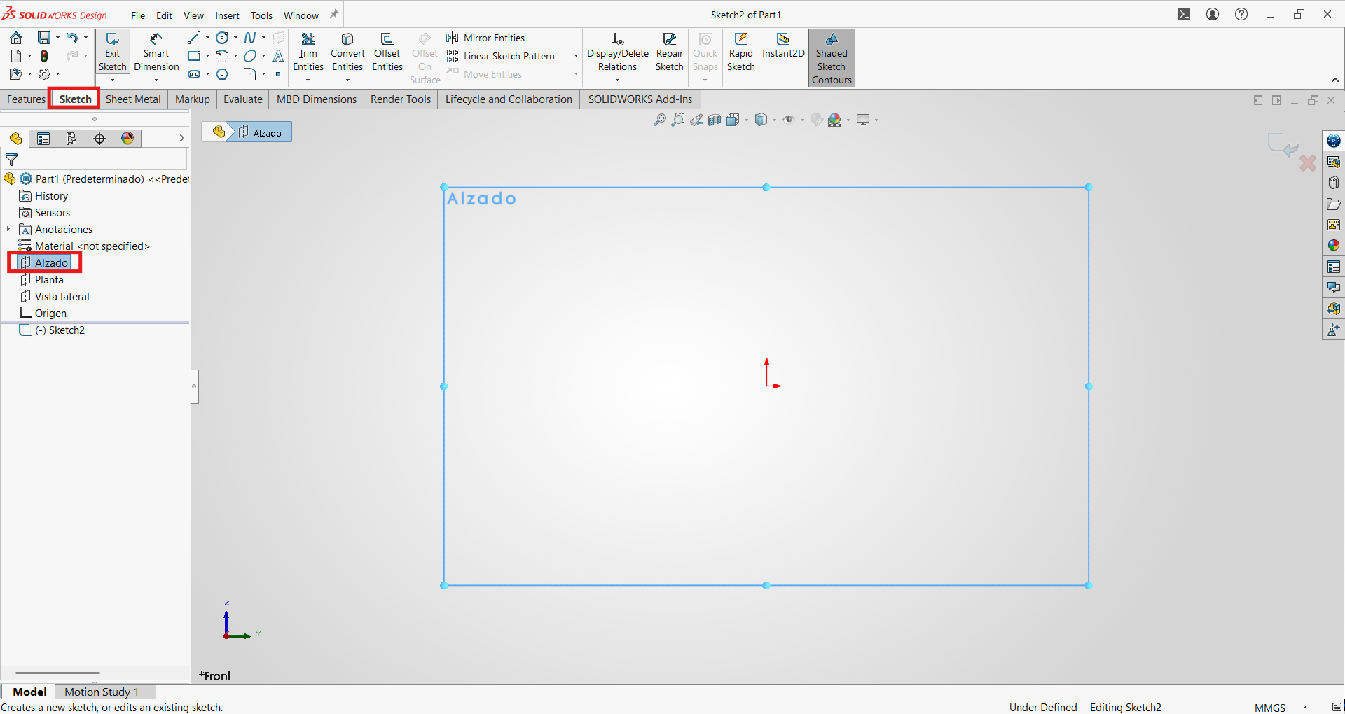
- First, we will create a new "Part" and click on "Sketch", selecting the front view to draw.
- Then we will draw one of the faces of our logo; in this case the total size will be 20x20 cm.
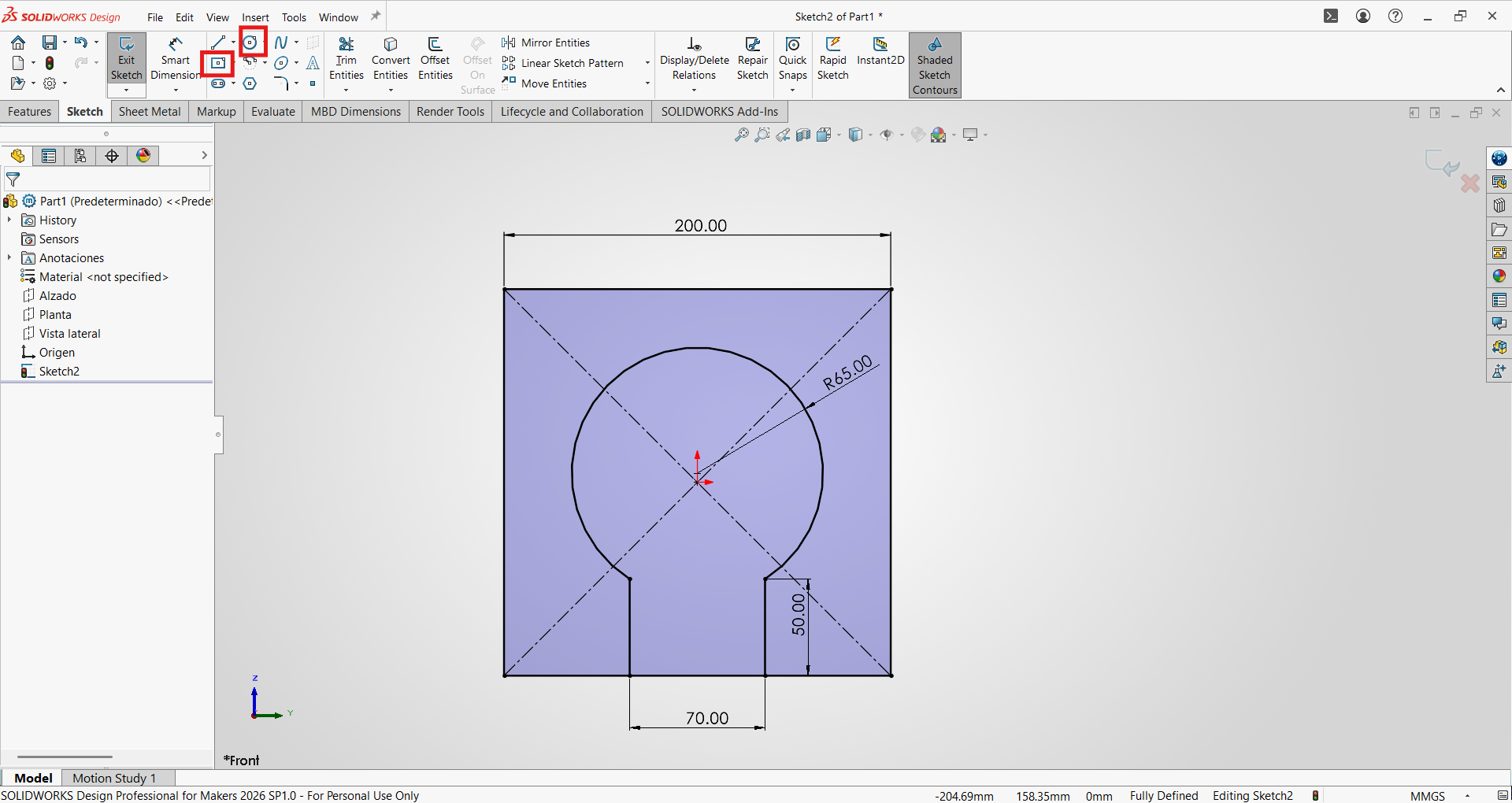
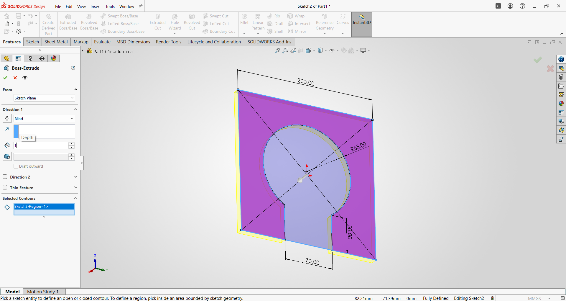
- We extrude by selecting the face area and using the Extruded operation; in this case the thickness will be 1mm for our sheet metal.
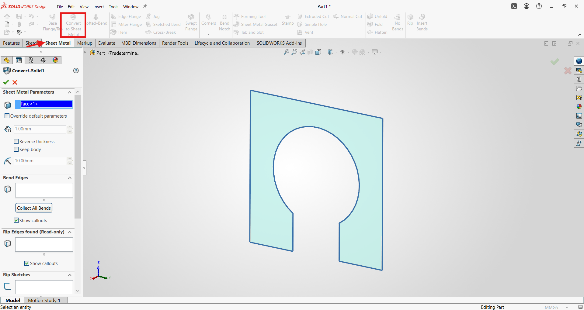
- We will convert our first face into sheet metal by clicking on the Sheet Metal tab and using the basic thickness settings.
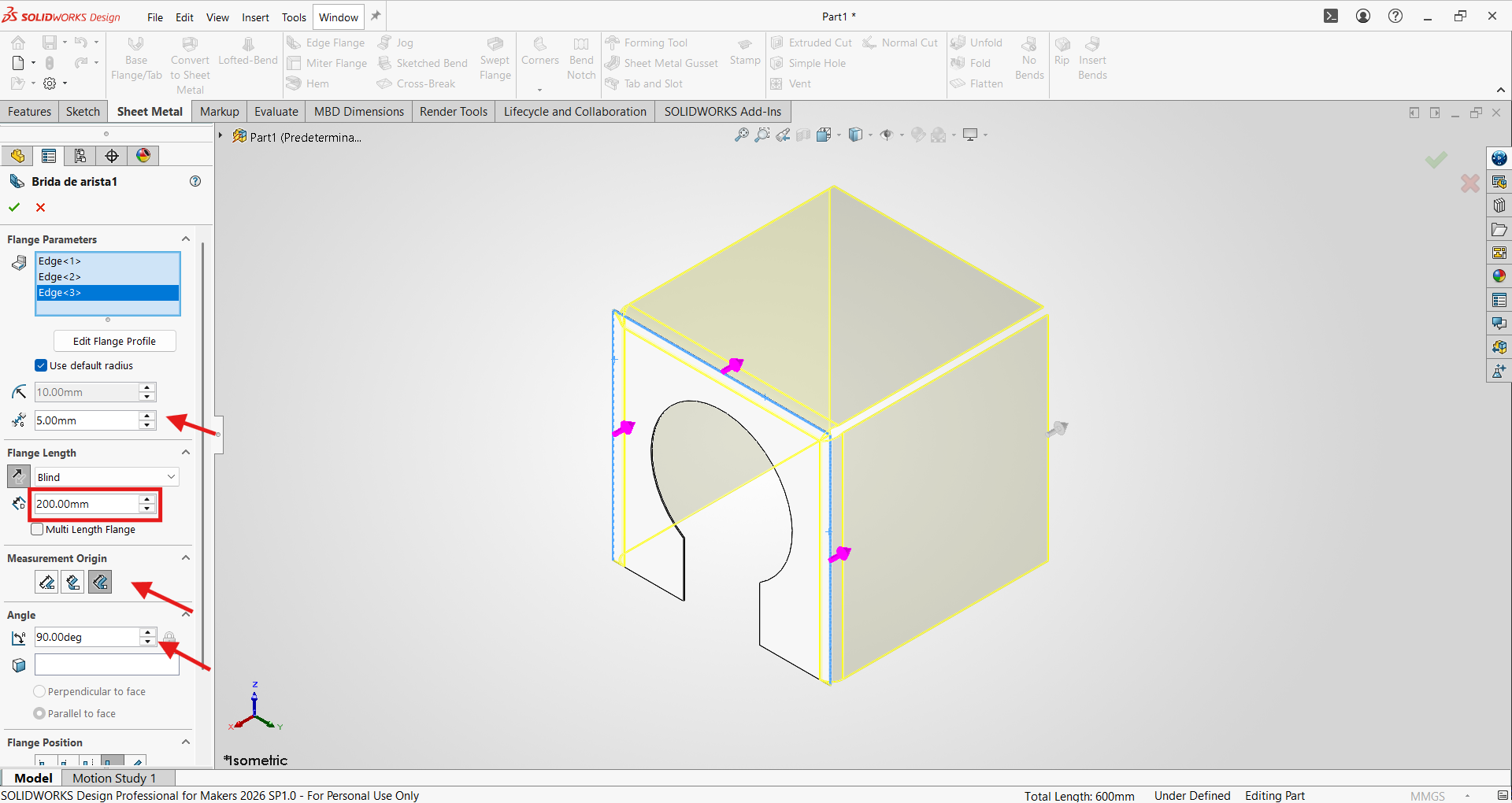
- Now using the Edge Flange command, we can create flanges on our sheet metal.
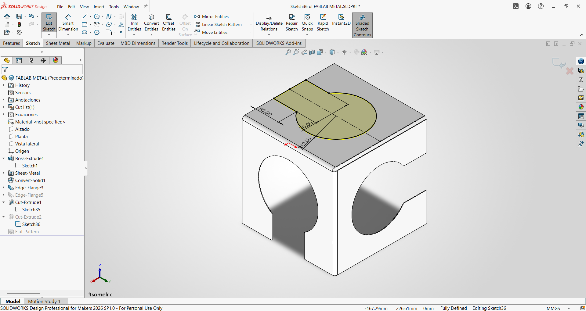
- Then we will sketch the shape of our logo on each face and cut it out.
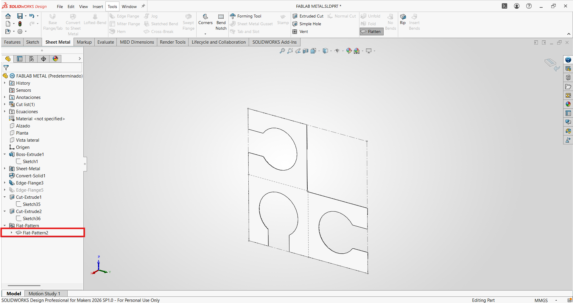
- We will verify that our sheet metal is correct by activating the "Flatten" view.
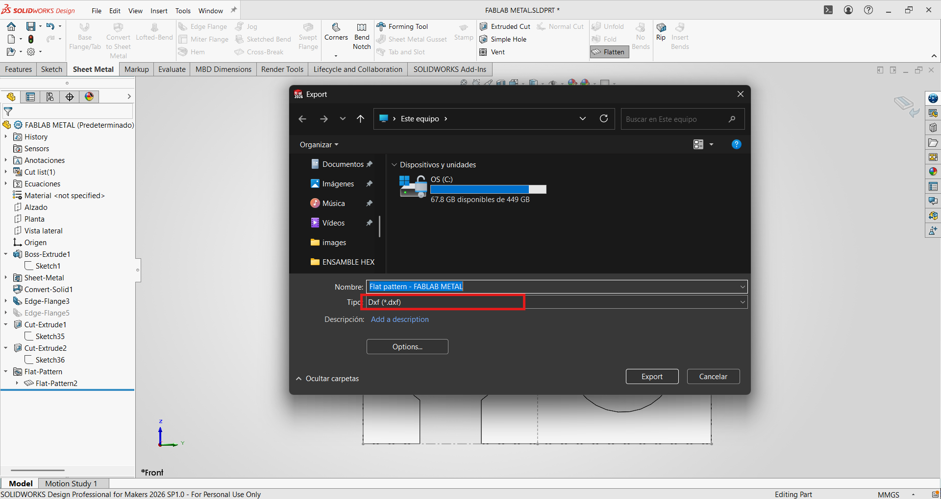
- Finally, we will export it in .dxf format for laser cutting.
Metal laser cutting
For the manufacturing process, a fiber laser cutting machine was used:
Machine characteristics:
- Machine type: Fiber laser cutting machine
- Brand: Camel CNC
- Power: 1.5kW
- Work area: 1500 x 3000 mm
- Software: CypOne- Laser Cutting Software 6.1.729.2
Material characteristics:
- Material: Stainless Steel 304
- Thickness: 1mm
The .dxf file was imported into CypOne, and the cutting parameters were configured for 1mm stainless steel using a simple 1.5mm nozzle.
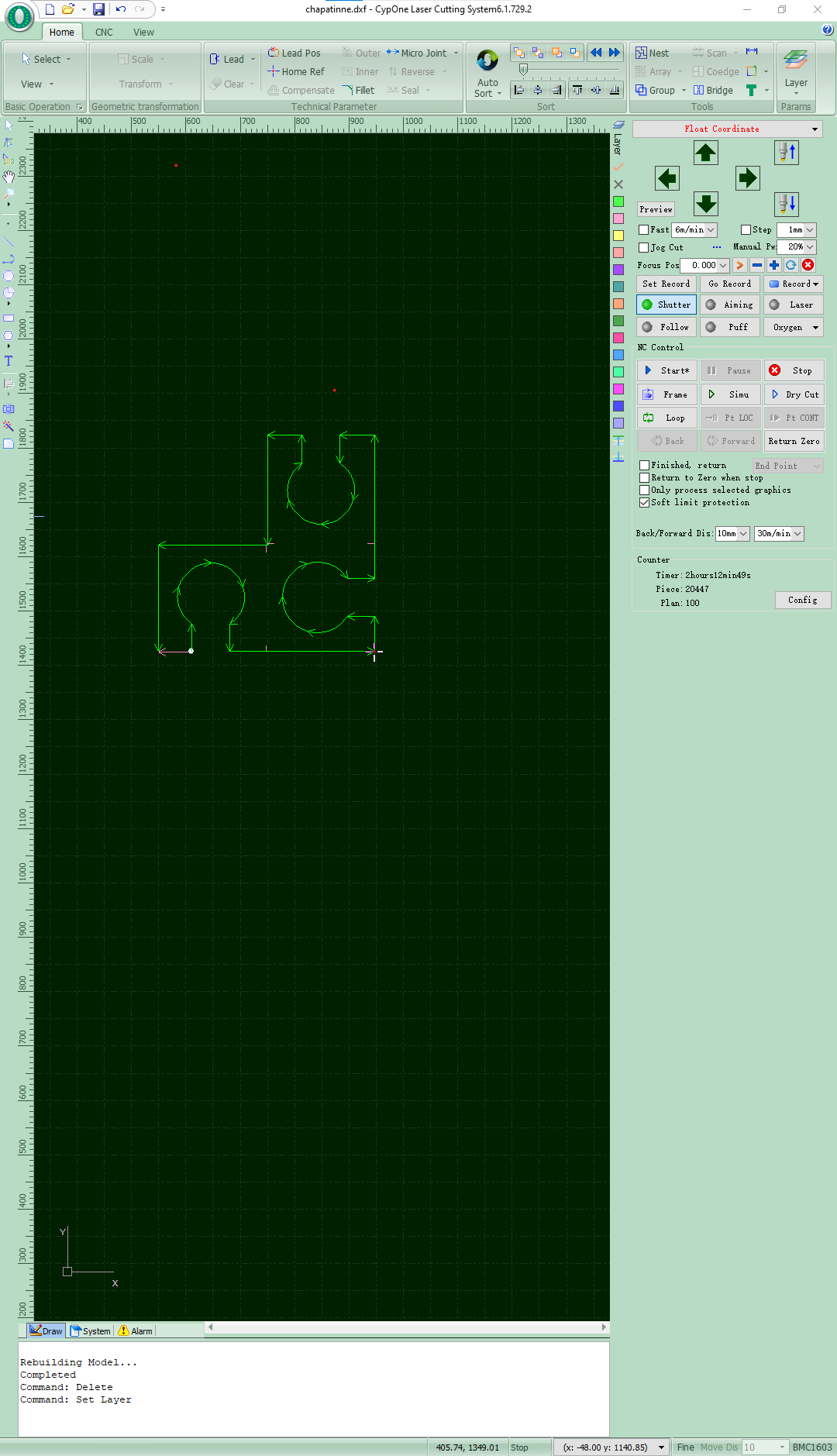
Cutting parameters:
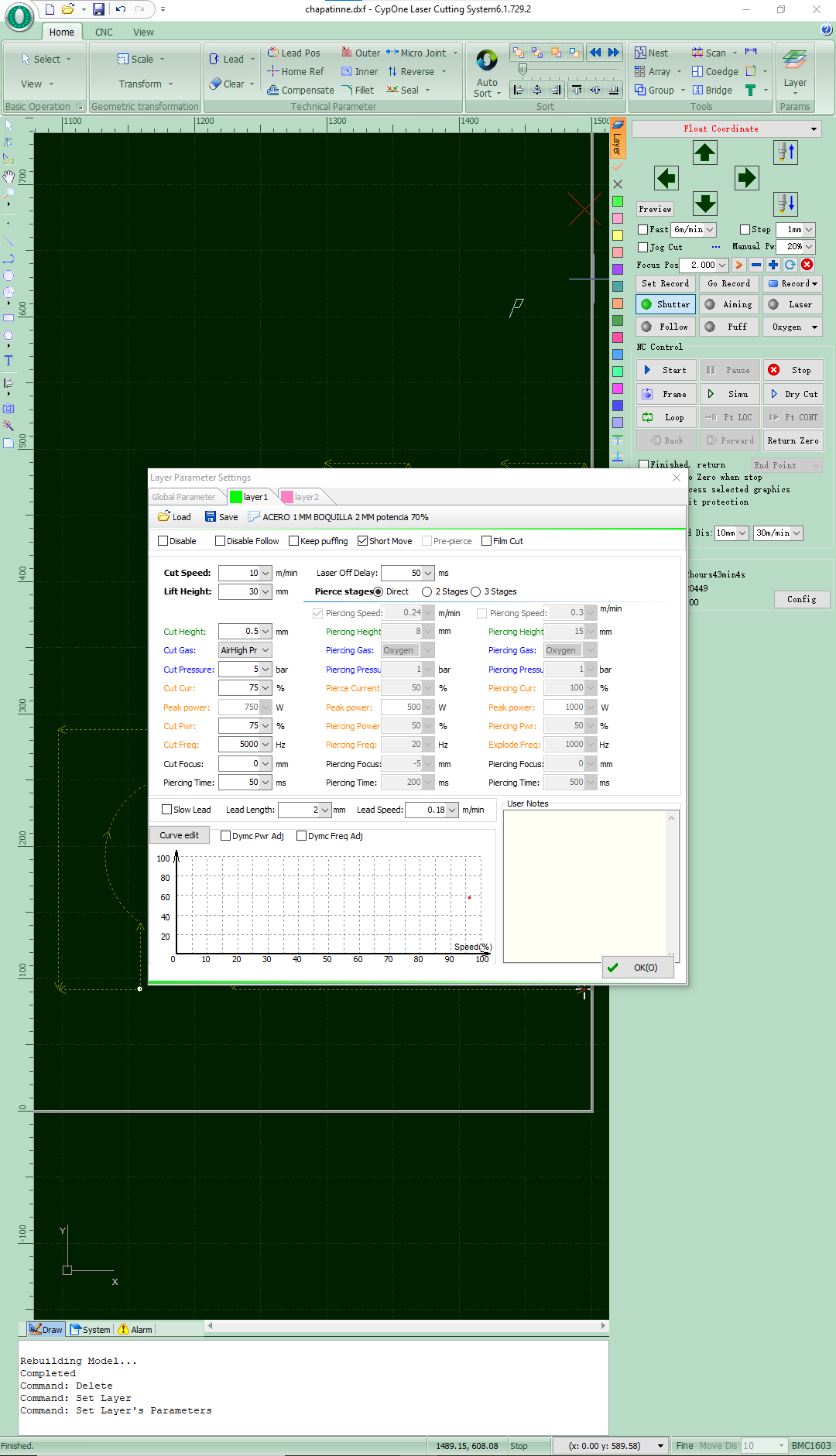
For the laser cutting process, a specific configuration was used to work on 1 mm thick stainless steel. The parameters were adjusted within the machine control software to obtain a clean, stable, and precise cut, optimizing both the cutting speed and the quality of the final finish.
| Parameter | Value |
|---|---|
| Material | Stainless steel |
| Thickness | 1 mm |
| Cutting speed | 10 m/min |
| Cutting height | 0.5 mm |
| Cutting gas | Air High Pressure |
| Gas pressure | 5 bar |
| Cutting power | 75 % |
| Peak power | 750 W |
| Cutting frequency | 5000 Hz |
| Focus position | 0 mm |
| Laser delay | 50 ms |
| Lead length | 2 mm |
| Lead speed | 0.18 m/min |
Additionally, the CypOne Laser Cutting System software was configured to control piercing, focus, and path compensation parameters before the cutting process began.
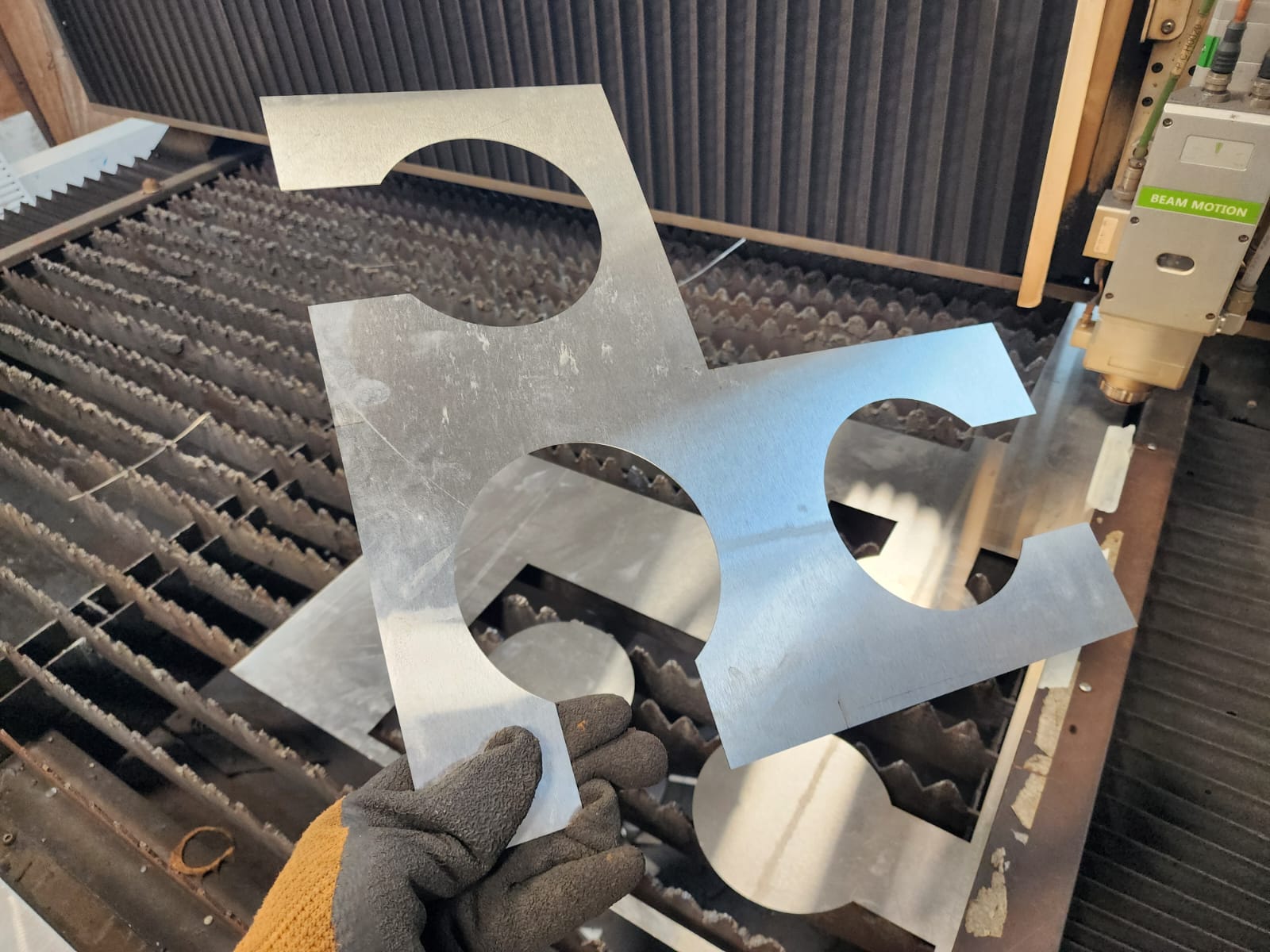
Cutting results
Bending the sheet metal
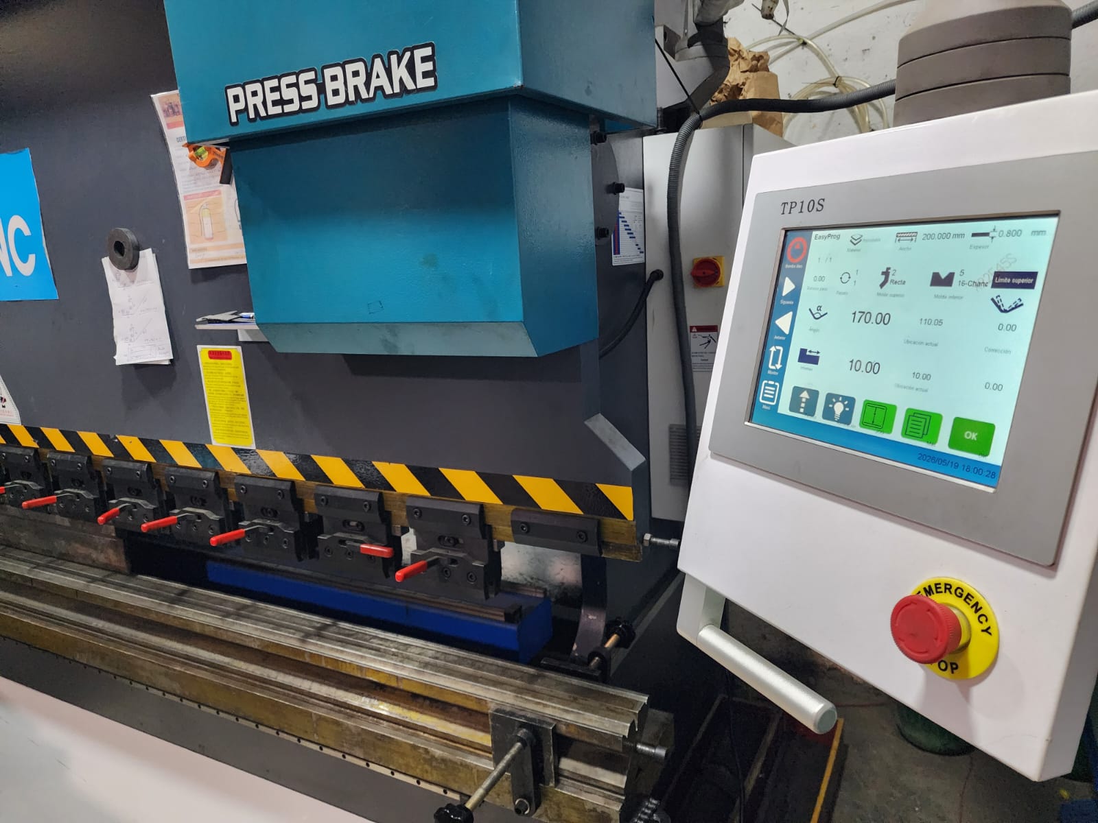
A press brake was used to bend the sheet metal according to the specified design.
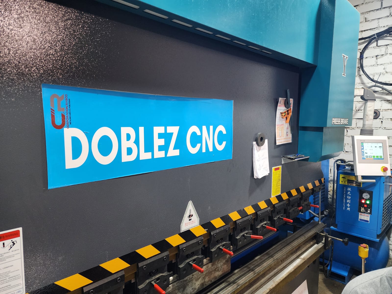
The parameters of thickness, bending angle, and upper die type were configured.
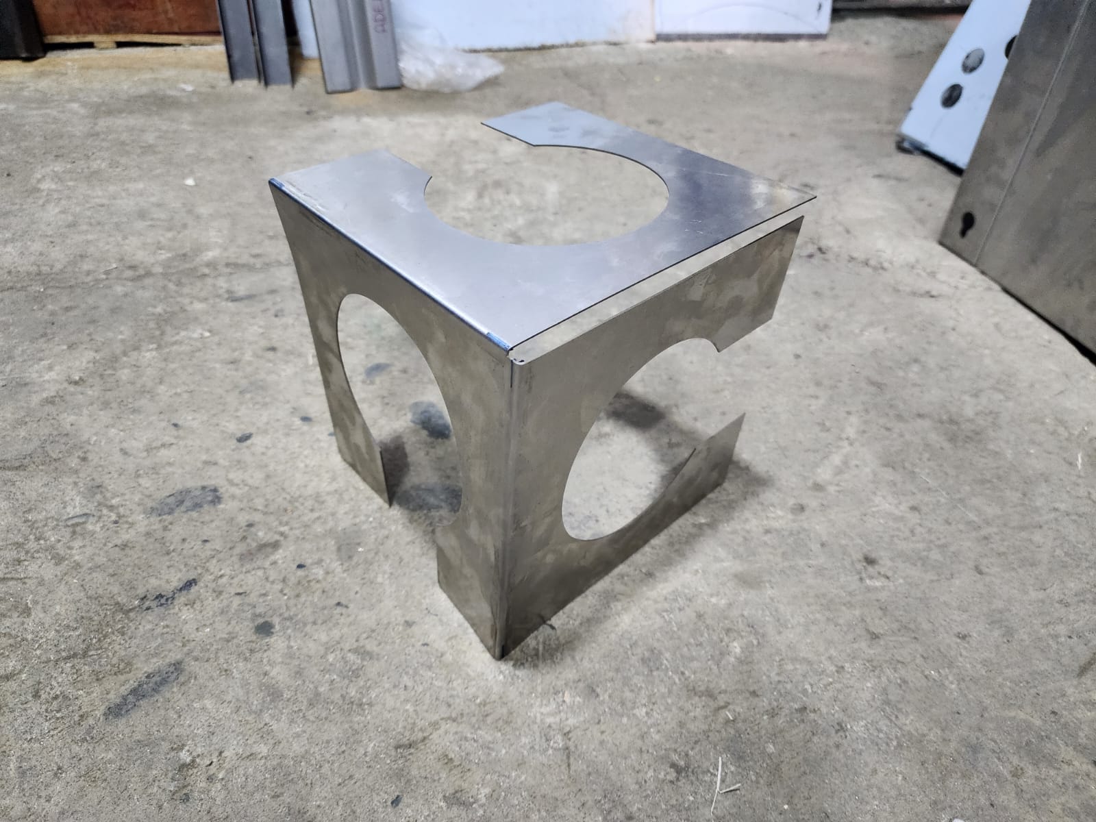
RESULTADO FINAL
Conclusions:
During this week I was able to work with a digital manufacturing workflow I had not explored before: the design and fabrication of sheet metal using fiber laser cutting and CNC bending. The process began in SolidWorks, where I used the Sheet Metal module to model the FABLAB logo cube in its three visible faces, with a thickness of 1 mm, using tools such as Edge Flange and the Flatten view to verify the flat pattern before exporting it in .DXF format.
The file was imported into the CypOne software of the 1.5 kW Camel CNC fiber laser cutting machine, where I configured the specific parameters for 1 mm stainless steel 304, including cutting speed, gas pressure, power, and frequency, achieving a clean and precise cut on the material. The piece was then processed on a CNC press brake, where the thickness, bending angle, and die type parameters were adjusted to transform the flat pattern into the final three-dimensional structure.
Overall, this week allowed me to integrate a complete industrial manufacturing process for the first time: from parametric CAD design to physical fabrication using two high-precision machines, obtaining a functional and reproducible result that represents the FABLAB logo in sheet metal.