WEEK 12
Mechanical Design, Machine Design
Group assignment:
- Design a machine that includes mechanism + actuation + automation + application.
- Build the mechanical parts and operate it manually.
- Actuate and automate your machine.
- Document the group project.
VIDEO
SLIDE
Individual Contribution:
- Mechanical Design
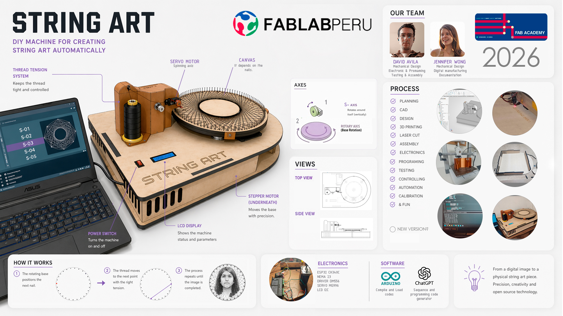
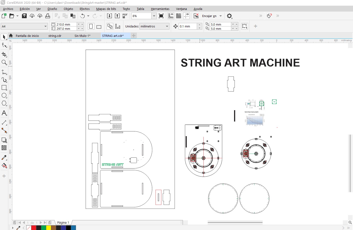
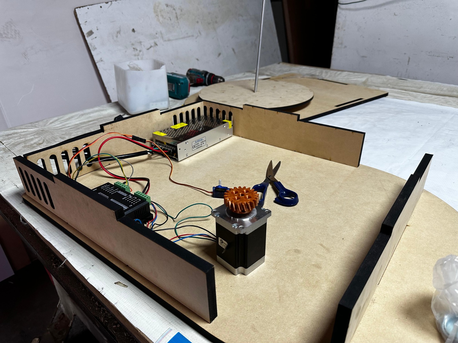
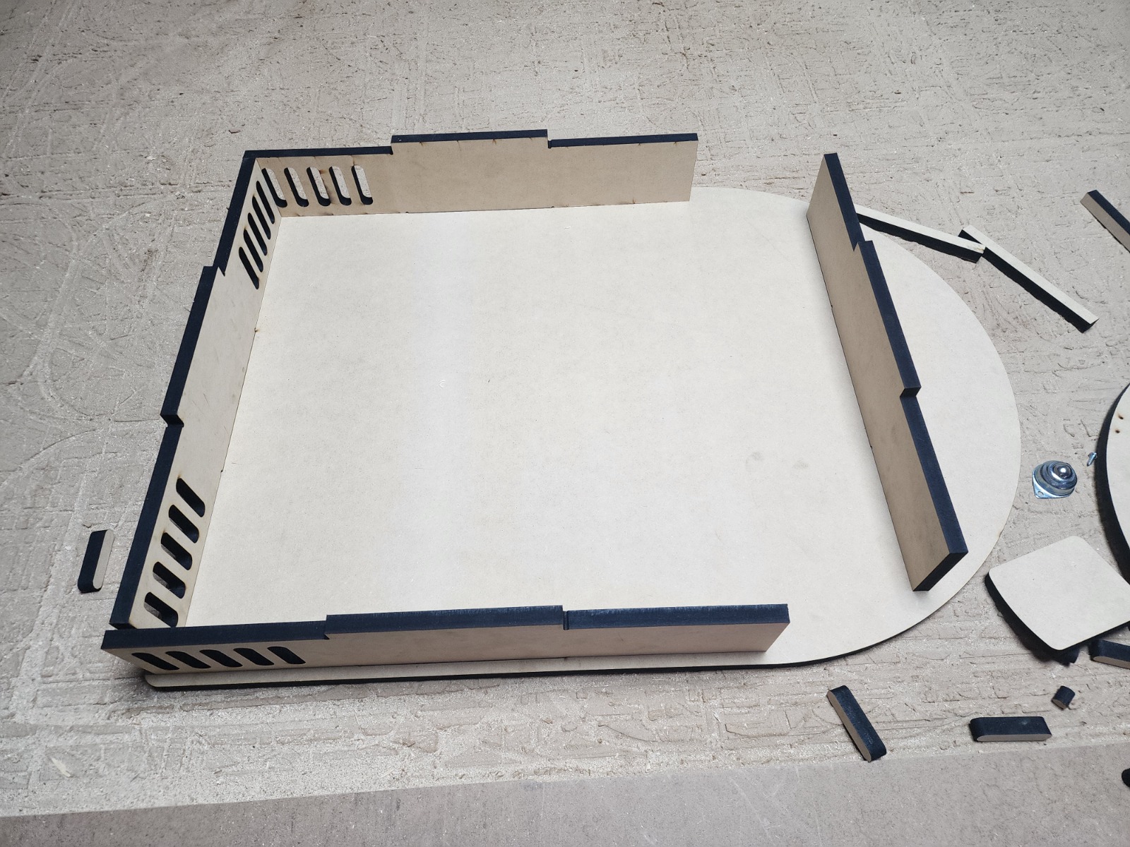
My contribution started with searching for materials to develop the mechanical design. On my side, I first reviewed the base structure, which I developed in a 2D plan using the 3D reference modeled by my teammate Jennifer. For this, I used Corel Draw to break down the base and prepare the file for laser cutting. I also designed the string art canvases and finally carried out several tests to identify what needed to be modified.
- Electronic & Programming
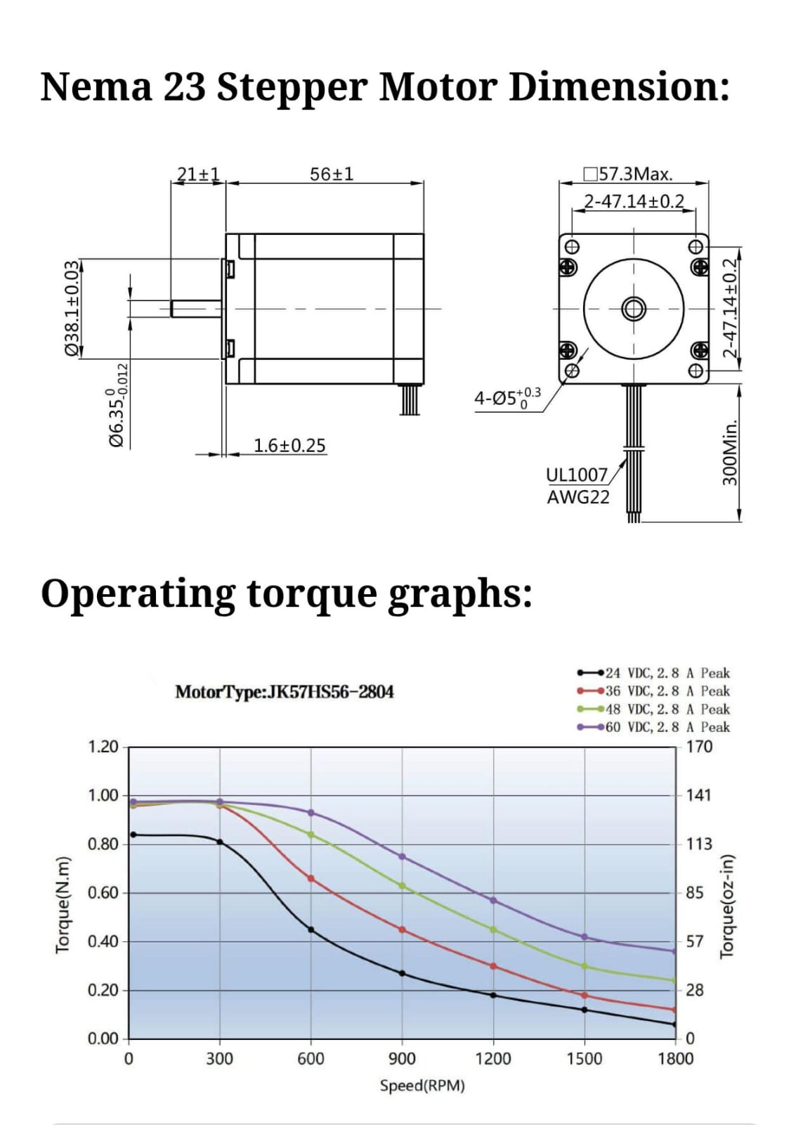
I first needed to understand the electronics of a stepper motor, so I researched its electronics and programming. Key parameters were good torque (1.2Nm), step angle (1.8°), and current (2A). Then I looked for a compatible driver, and the DM556 was the most recommended for these motors. I reviewed its datasheet and, with AI support, configured and made the connections on my shield for my ESP32. Once finished, I asked AI for a test code to rotate our stepper motor.
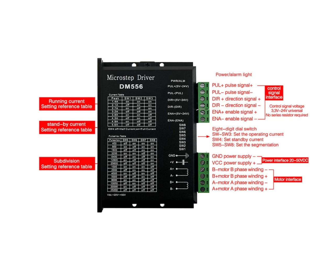
DIGITAL STEPPER DRIVER DM566
This test code was generated in Gemini according to the connections I made on my shield, and it allowed us to test the back-and-forth movement as an initial validation.
// Pins
#define STEP_PIN 2   // D2
#define DIR_PIN  4   // D4

void setup() {
  pinMode(STEP_PIN, OUTPUT);
  pinMode(DIR_PIN, OUTPUT);

  digitalWrite(DIR_PIN, HIGH); // Initial direction
}

void loop() {

  // Rotate in one direction
  digitalWrite(DIR_PIN, HIGH);

  for (int i = 0; i < 2000; i++) { // steps
    digitalWrite(STEP_PIN, HIGH);
    delayMicroseconds(500); // speed
    digitalWrite(STEP_PIN, LOW);
    delayMicroseconds(500);
  }

  delay(1000);

  // Change direction
  digitalWrite(DIR_PIN, LOW);

  for (int i = 0; i < 2000; i++) {
    digitalWrite(STEP_PIN, HIGH);
    delayMicroseconds(500);
    digitalWrite(STEP_PIN, LOW);
    delayMicroseconds(500);
  }

  delay(2000);
}
In the video you can see the connections and the movement of the stepper motor. On the group page you can find the rest of the electronics and the final programming.
- Testing & Assembly
I was able to assemble everything once each part was cut and 3D printed. A press-fit design and screw anchors were used on the weaving head, as well as for securing the motor and other required components. It was necessary to run several tests on the needle and thread tension; a lollipop stick worked better as a needle guide, along with using a 100-nail test for the initial canvas.
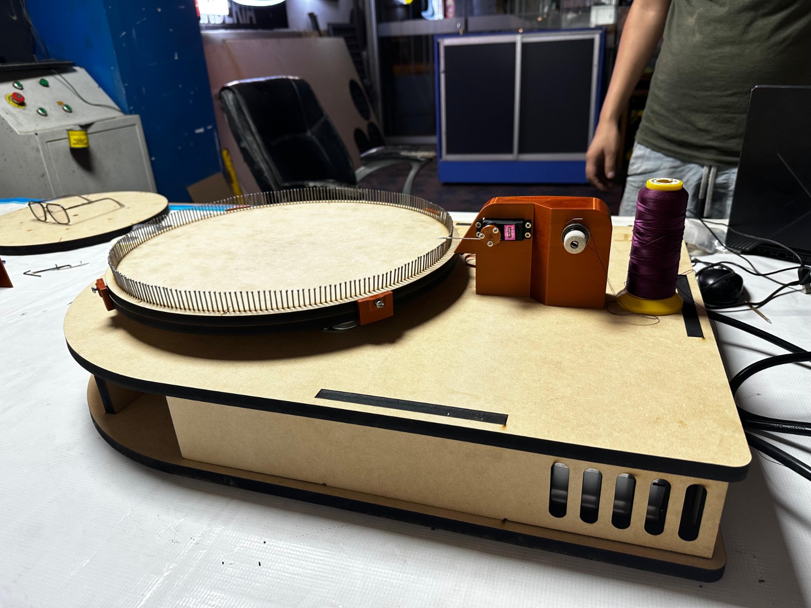
The final assembly included adding more elements such as an LCD screen, some clamps, and different supports for the canvas. In the end, we achieved a final AI-generated code to create a geometric canvas.
#include
#include
#include

// ---------------- LCD ----------------
LiquidCrystal_I2C lcd(0x27, 16, 2);

// ---------------- PINS ----------------
const int stepPin = 14;
const int dirPin  = 27;
const int servoPin = 13;

// ---------------- SERVO ----------------
Servo aguja;

const int ANGULO_ARRIBA = 40;
const int ANGULO_ABAJO  = 5;

// ---------------- CONFIG ----------------
const float pasosPorVuelta = 9600.0;
const int totalClavos = 100;

const int offsetAngular = 3;
const int pasosOffset = 85;

// SECUENCIA OPTIMIZADA
int secuencia[] = {
  0,17,34,51,68,85,2,19,36,53,70,87,4,21,38,55,72,89,6,23,
  40,57,74,91,8,25,42,59,76,93,10,27,44,61,78,95,12,29,46,63,
  80,97,14,31,48,65,82,99,16,33,50,67,84,1,18,35,52,69,86,3,
  20,37,54,71,88,5,22,39,56,73,90,7,24,41,58,75,92,9,26,43,
  60,77,94,11,28,45,62,79,96,13,30,47,64,81,98,15,32,49,66,83
};

const int totalPasos = sizeof(secuencia) / sizeof(secuencia[0]);

// ---------------- VARIABLES ----------------
float posicionActual = 0.0;

unsigned long tiempoInicio = 0;
unsigned long ultimoLCD = 0;
unsigned long ultimoSerial = 0;

int progresoGlobal = 0;

// ---------------- LCD ----------------

void actualizarLCD() {

  if (millis() - ultimoLCD < 200) return;
  ultimoLCD = millis();

  unsigned long tiempoActual = millis() - tiempoInicio;

  int segundos = tiempoActual / 1000;
  int minutos = segundos / 60;
  segundos = segundos % 60;

  lcd.setCursor(0, 0);
  lcd.print("String Art 1.0");

  lcd.setCursor(0, 1);
  lcd.print("Prog: ");

  if (minutos < 10) lcd.print("0");
  lcd.print(minutos);
  lcd.print(":");
  if (segundos < 10) lcd.print("0");
  lcd.print(segundos);

  lcd.setCursor(12, 1);

  if (progresoGlobal < 100) lcd.print(" ");
  if (progresoGlobal < 10) lcd.print(" ");

  lcd.print(progresoGlobal);
  lcd.print("%");
}

// ---------------- SERIAL ----------------

void actualizarSerial(int i, int origen, int destino) {

  if (millis() - ultimoSerial < 300) return;
  ultimoSerial = millis();

  unsigned long tiempoActual = millis() - tiempoInicio;

  int segundos = tiempoActual / 1000;
  int minutos = segundos / 60;
  segundos = segundos % 60;

  Serial.print("[");
  if (minutos < 10) Serial.print("0");
  Serial.print(minutos);
  Serial.print(":");
  if (segundos < 10) Serial.print("0");
  Serial.print(segundos);
  Serial.print("] ");

  Serial.print("Paso ");
  Serial.print(i);
  Serial.print(" | ");

  Serial.print(origen);
  Serial.print(" -> ");
  Serial.print(destino);

  Serial.print(" | ");
  Serial.print(progresoGlobal);
  Serial.println("%");
}

// ---------------- MOTOR ----------------

void stepMotor(long pasos, bool dir) {
  digitalWrite(dirPin, dir);

  for (long i = 0; i < pasos; i++) {
    digitalWrite(stepPin, HIGH);
    delayMicroseconds(500);
    digitalWrite(stepPin, LOW);
    delayMicroseconds(500);
  }
}

void irAClavo(int clavo) {

  float pasosObjetivo = (pasosPorVuelta * clavo) / totalClavos;

  float delta = pasosObjetivo - posicionActual;
  bool sentido = (delta >= 0);

  if (sentido) pasosObjetivo += offsetAngular;
  else pasosObjetivo -= offsetAngular;

  delta = pasosObjetivo - posicionActual;

  stepMotor(abs((long)delta), sentido);

  posicionActual += (long)delta;
}

// ---------------- SERVO ----------------

void bajarAguja() {
  aguja.write(ANGULO_ABAJO);
  delay(200);
}

void subirAguja() {
  aguja.write(ANGULO_ARRIBA);
  delay(200);
}

void engancharHilo() {

  bajarAguja();
  stepMotor(pasosOffset, HIGH);
  subirAguja();
}

// ---------------- SETUP ----------------

void setup() {
  pinMode(stepPin, OUTPUT);
  pinMode(dirPin, OUTPUT);

  aguja.attach(servoPin);
  subirAguja();

  lcd.init();
  lcd.backlight();

  Serial.begin(115200);
  Serial.println("=== INICIO STRING ART ===");

  lcd.setCursor(0, 0);
  lcd.print("String Art 1.0");
  lcd.setCursor(0, 1);
  lcd.print("Starting...");
  delay(2000);

  lcd.clear();

  tiempoInicio = millis();
}

// ---------------- LOOP ----------------

void loop() {

  for (int i = 0; i < totalPasos - 1; i++) {

    progresoGlobal = (i * 100) / totalPasos;

    int origen = secuencia[i];
    int destino = secuencia[i + 1];

    actualizarLCD();
    actualizarSerial(i, origen, destino);

    irAClavo(origen);
    engancharHilo();
  }

  // -------- FIN --------

  unsigned long tiempoTotal = millis() - tiempoInicio;

  int segundos = tiempoTotal / 1000;
  int minutos = segundos / 60;
  segundos = segundos % 60;

  lcd.clear();

  lcd.setCursor(0, 0);
  lcd.print("String Art 1.0");

  lcd.setCursor(0, 1);
  lcd.print("Finish! ");

  if (minutos < 10) lcd.print("0");
  lcd.print(minutos);
  lcd.print(":");
  if (segundos < 10) lcd.print("0");
  lcd.print(segundos);

  Serial.println("=== FINISHED ===");

  while (true) {
  }
}
For more detail about my individual process, you can review my group page where all the documentation of my mechanical part, electronics, and programming is available, as well as test videos and the final AI-generated code.
Conclusions:
- In Week 12, I managed to integrate mechanical design + electronics + programming into a single functional machine.
- I validated system behavior through stepper motor movement tests, direction tuning, and speed control.
- The assembly stage confirmed that a good structure design, proper fixings, and thread guidance improve the project's mechanical stability.
- I learned to iterate between physical prototyping and code adjustments to obtain more accurate tracing results.
- Using AI resources helped me speed up code generation and focus on real system calibration.
- Video documentation and group testing were key to comparing results and making technical decisions during development.
- As an overall conclusion, this week strengthened my foundation to implement a complete automation system in my final project.
- A future improvement is to optimize execution times, reduce vibrations, and refine thread tension to increase the final string art quality.