Week 07 – Computer-Controlled Machining

This week is focused on Computer-Controlled Machining: learning how to work safely with the large CNC machine, understanding machine setup and CAM workflows, and designing and producing a large object using 2D machining processes.
On this page I document:
- The group assignment: lab safety training and testing the CNC machine parameters.
- My 2D design workflow for large format CNC production.
- The CAM process: toolpaths, feeds, speeds, tabs, and machining strategy.
- The manufacturing and assembly of my final large object.
- The problems I found and how I solved them.
Assignment and Learning Outcomes
The weekly assignment is:
- Group assignment:
- Complete your lab’s safety training.
- Test runout, alignment, fixturing, speeds, feeds, materials and toolpaths for your machine.
- Document your work on the group work page and reflect on your individual page what you learned.
- Individual assignment:
- Make (design + mill + assemble) something big.
The learning outcomes are:
- Demonstrate 2D design development for CNC milling production.
- Describe workflows and operation for large format CNC machining.
Checklist
In this page I answer the required questions:
- Linked to the group assignment page.
- Reflected on my individual page what I learned from the lab safety training.
- Documented how I designed my object and made my CAM toolpath.
- Documented how I milled and assembled my final product, including machine setup, fixturing, feeds and speeds.
- Described problems and how I fixed them.
- Included my design files and a hero shot of the final product.
You can see the group documentation here:

Group Assignment – Safety Training and CNC Characterization
For the group assignment we first completed the lab safety training for the large format CNC machine. After that, we tested the machine to better understand its behaviour and the main parameters that affect machining quality and safety.
Safety Training
During the training I learned the most important safety rules before operating the CNC machine:
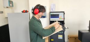
- Always wear appropriate personal protective equipment.
- Check that the board is correctly fixed to the sacrificial layer before starting.
- Verify that the tool is properly mounted and tightened.
- Keep the working area clean and never leave loose objects on the bed.
- Know the location of the emergency stop and be ready to use it.
- Never put hands near the spindle while the machine is operating.
- Stay close to the machine during cutting in case vibration, broken tools, or loose material appear.

The most important thing I learned is that CNC machining is not only about sending a file to a machine. It requires careful preparation, supervision, and understanding of the risks.
Machine Tests
As a group, we tested different aspects of the CNC workflow and machine condition:
- Runout of the tool/spindle.
- Alignment of the machine and board placement.
- Fixturing methods using screws and hold-down strategy.
- Feeds and speeds for the selected material.
- Toolpaths for inside cuts, outside cuts, pockets, and tabs.
- Material behaviour during cutting.
What We Observed
- If the board is not well fixed, vibration can affect the cut quality and become unsafe.
- Wrong feeds and speeds can burn the wood, overload the spindle, or produce poor edge finish.
- Tabs are essential to prevent pieces from moving during the final pass.
- Correct zeroing of X, Y, and especially Z is critical for accurate depth and clean cuts.
- Tool diameter must be considered in the design because internal corners cannot be perfectly square.
This group work helped me understand the real machine constraints before starting my own project.
Individual Assignment – Make Something Big (and useful)
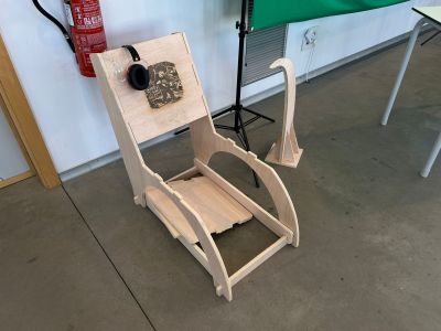
For this assignment I designed, milled and assembled a large parametric chair using the CNC router. The model was created in FreeCAD using a parametric workflow, which allows the dimensions and slot sizes to be easily modified depending on the material thickness.
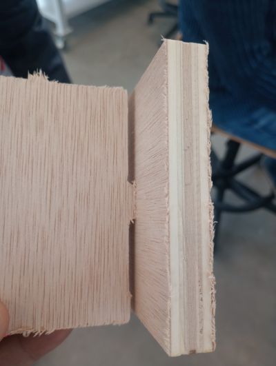
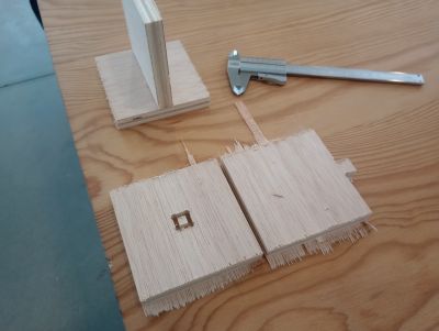
Before starting the design, I measured the thickness of the laminated plywood using a caliper. Although the nominal thickness of the board was 15 mm, the real measured thickness was 15.3 mm. This value was used as a parameter in the design to ensure a correct press-fit assembly.
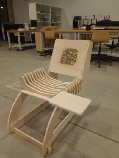
The final result is a large CNC-milled chair made from interlocking 2D parts cut from a wooden board. The structure is assembled using slots designed according to the measured material thickness.
- The chair was designed using parametric modelling in FreeCAD.
- The material thickness parameter was set to 15.3 mm after measuring the board.
- All components were exported as 2D profiles for CNC machining.
- The structure is assembled using press-fit joints.
- The design can be easily adapted to other materials by changing the thickness parameter.
To ensure a proper press-fit assembly, the slots were designed slightly larger than the measured thickness to compensate for machining tolerances and tool diameter. (group assignement)
2D Design Development
Concept
The goal of this assignment was to design and fabricate a large parametric chair using CNC machining. The chair was designed using a parametric approach in FreeCAD, allowing the geometry to adapt automatically to the material thickness and other design parameters. The structure is composed of several interlocking flat parts that can be cut from a wooden board and assembled using press-fit joints without complex hardware.
Design Considerations
- The laminated plywood thickness was measured with a caliper, obtaining a value of 15.3 mm.
- The slot width in the design was adjusted according to the measured thickness to achieve a press-fit joint.
- The tool diameter was considered to avoid problems in internal corners during CNC milling.
- The structure of the chair was designed to ensure mechanical stability once assembled.
- The parts were arranged to allow efficient nesting on the wooden board and reduce material waste.
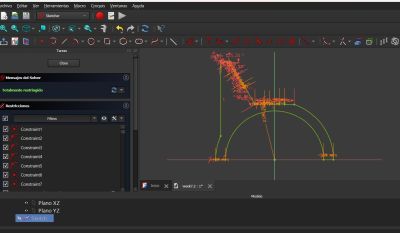
Software Workflow
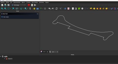
- FreeCAD was used to create the parametric 3D model of the chair.
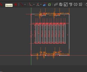
- The components were derived from the parametric model and exported as 2D profiles.
- The vectors were prepared for CNC machining in the CAM software.
In this pictures you can see the FreeCad design of the parts for more details open the files
Working progress
At this stage I also checked dimensions and adjusted the slot width based on the real material thickness, because nominal thickness and actual thickness are not always the same.
CAM Workflow and Toolpath Preparation
After finishing the parametric design of the chair in FreeCAD, the next step was preparing the files for CNC machining. The 2D profiles generated from the model were exported and imported into the CAM software Cult3D, where the toolpaths were defined. Since the CNC machine cannot interpret the CAD model directly, the CAM stage defines the movements of the cutter, including cutting depth, order of operations and machining strategy.
CAM Steps
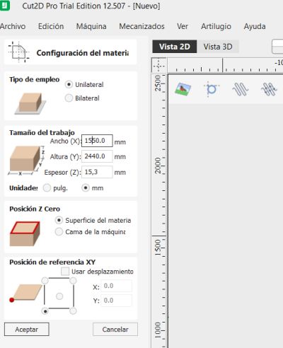
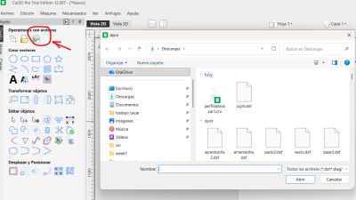
- Import the exported 2D vectors from FreeCAD into the CAM software (Cult3D).
- Define the material dimensions and the measured thickness.
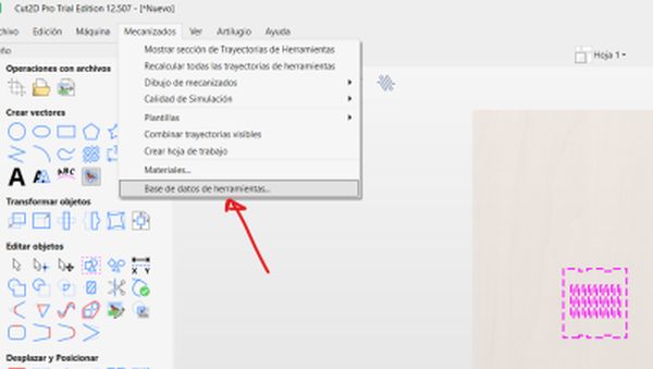
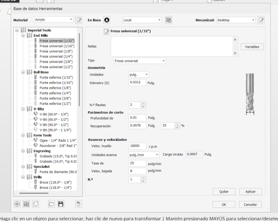
- Select the appropriate cutting tool (6mm) for plywood machining.
- Assign machining operations:
- Inside cuts for slots and internal joints.
- Outside cuts for the external contours of the chair parts.
- Pockets where partial material removal was required.
- Add tabs to keep the parts attached to the board during machining.
- Define machining parameters such as cut depth, pass depth, spindle speed and feed rate.
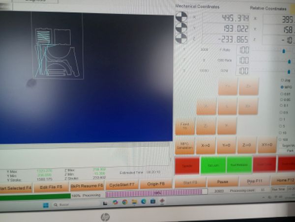
- Run the toolpath simulation to verify the order of operations and detect possible errors.
Machining Parameters
- Material: laminated plywood.
- Measured thickness: 15.3 mm (measured with a caliper).
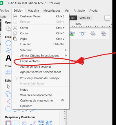
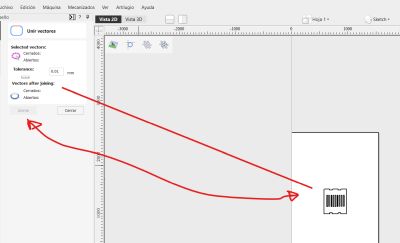
- Import:Select the files
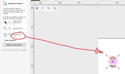
- Close vectors: Close verctors
- Select tools: select tools for milling
During the machining setup, all internal cuts were processed before the external contours to ensure the parts remained fixed to the board until the end of the operation. This prevents movement of the pieces and improves machining safety and precision.
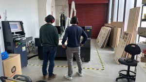
Machine Setup and CNC Operation
Preparing the Machine
- Clean the CNC bed and sacrificial board.
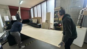
- Place the material sheet on the bed.
- Fix the board with screws in safe areas outside the cutting paths.
- Install the correct tool in the spindle.
- Set the machine origin for X, Y, and Z.
- Load the toolpath file into the machine control software.
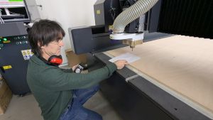
- Run a final visual check before starting.
Fixturing
Proper fixturing was one of the key points of this week. I used screws to secure the board firmly to the sacrificial layer. I had to make sure the screws were far from the cutting area, but close enough to avoid material vibration.
Feeds, Speeds and Cutting Strategy
Based on the material and tool, I selected the feed and speed values recommended in the lab and adjusted them according to the group tests. I also used multiple passes instead of cutting the full thickness in one pass, which reduces stress on the tool and improves safety.
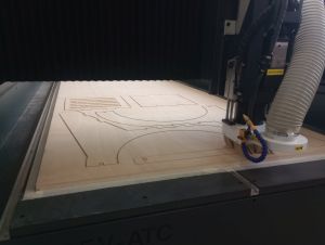
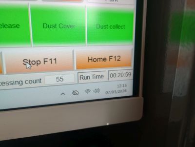
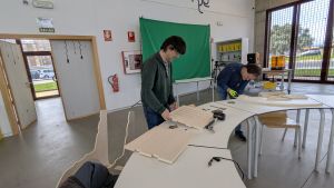
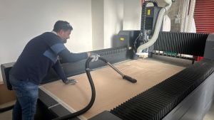
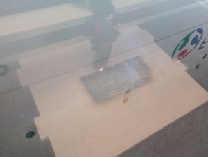
Milling Process
After all checks were completed, I started the machining process. I stayed close to the machine during the whole operation to supervise the cut and be ready to stop it if necessary.
Sequence
- First, the machine cut the internal features and slots.
- Then it machined any pocket operations if needed.
- Finally, it cut the outer contours of the parts.
- The tabs kept the pieces attached to the board until the job finished.
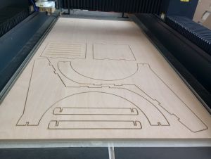
Once the milling was finished, I removed the board from the machine and cut the tabs manually. Then I cleaned the edges and prepared the parts for assembly.
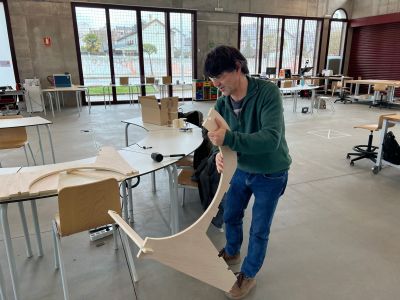
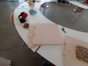
Assembly of the Final Product
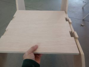
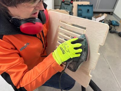
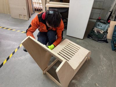
After machining, I assembled the object by inserting the parts into their corresponding slots. Since the design is based on press-fit construction, the tolerances were very important.
- I tested the fit of the first joints carefully.
- Some edges needed light sanding to improve the assembly.
- After adjustment, the structure became stable and self-supporting.
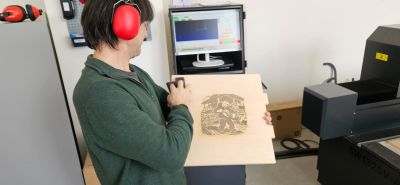
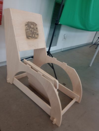
The final result was a large object made from CNC-cut parts, showing the complete workflow: design, CAM preparation, machining, and assembly.
Problems and Fixes
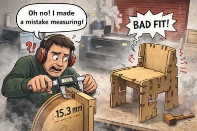
Measurement Mistake in the Seat
- Problem: I made a mistake when measuring the material and this affected the seat dimensions, so the first version did not fit correctly.
- Fix: I reviewed the measurements, corrected the design parameters, and remade the seat with the proper dimensions.
Redesign as an Opportunity
- Problem: Since I had to remake the seat, the first result did not fully match the final intention of the project.
- Fix: I took this redesign as an opportunity to add an artistic touch to the chair, because it is intended to be used while playing the hurdy-gurdy.
These issues helped me understand that CNC machining is not only about drawing shapes, but also about considering the real behaviour of the material, the tool diameter, the machining tolerances, and the importance of verifying measurements before production. At the same time, the redesign allowed me to improve the final result and give the chair a more personal and artistic character.
Design Files and Hero Shot
Design Files
- 2D design file –freecad
- 2D design file –freecad
- 2D design file –freecad
- CAM toolpath screenshots / crv
- FILE 1 DXF
- FILE 2 DXF
- FILE 3 DXF
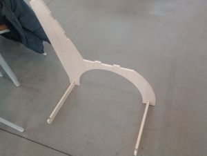
Hero Shot
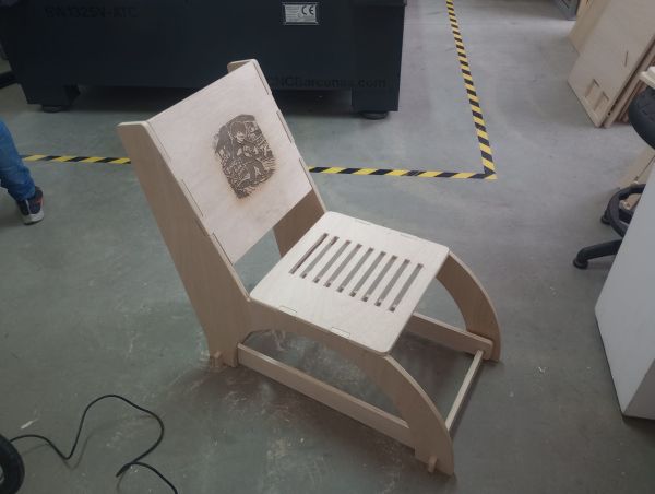
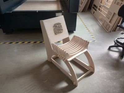
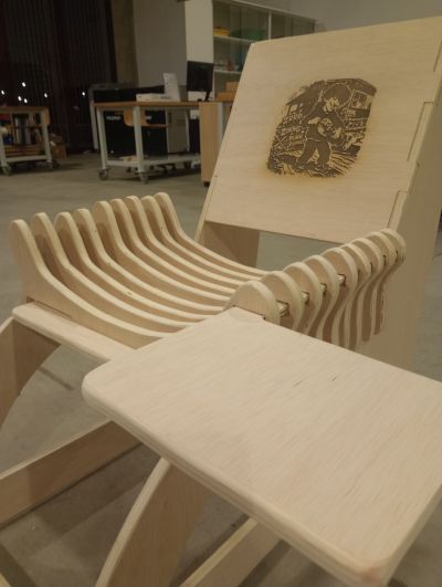
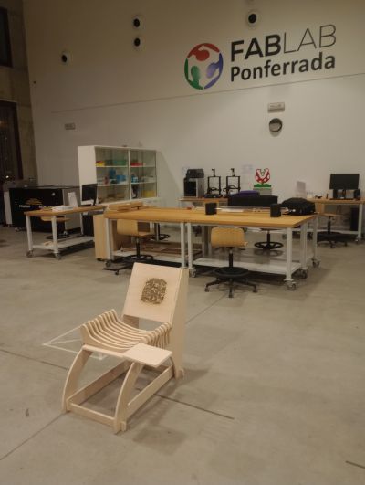
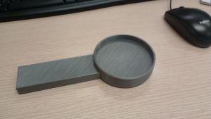
This is the final result: a chair that I can use to play the hurdy-gurdy, and to which I can add different accessories such as a table for reading sheet music or a 3D-printed holder for drinks.
Summary and Reflection
This week helped me understand the complete workflow of large format CNC machining, from safety and machine preparation to CAD design, CAM setup, machining, and assembly.
I learned that designing for CNC means thinking in 2D production logic: part layout, material thickness, tool diameter, internal corners, tabs, and assembly tolerances. These details strongly affect whether the final object will fit and work correctly.
I also learned that safety and fixturing are as important as the design itself. A correct setup, proper feeds and speeds, and continuous supervision are essential for good results and safe operation.
The final result was a successfully machined and assembled large object, and this assignment gave me much more confidence in using CNC machining as a production method for furniture-scale parts.