Week 05 – 3D Scanning and Printing
This week is focused on 3D Scanning and Printing: testing and understanding the design rules of our 3D printers, and using 3D scanning workflows to digitize physical objects.
On this page I document:
- The group assignment: 3D printer characterization and design rules.
- My individual 3D-printed object that cannot be easily made subtractively.
- My 3D scanning workflow and how I used it to digitize an object.
- The original design files and hero shots.
Assignment and Learning Outcomes
The weekly assignment is:
- Group assignment:
- Test the design rules for your 3D printer(s).
- Document your work on the group page and reflect on your individual page what you learned.
- Individual assignment:
- Design, document and 3D print an object (small, few cm³, limited by printer time) that could not be easily made subtractively.
- 3D scan an object (and optionally print it).
The learning outcomes are:
- Identify the advantages and limitations of 3D printing.
- Apply design methods and production processes to show your understanding of 3D printing.
- Demonstrate how scanning technology can be used to digitize object(s).
Checklist
In this page I answer the required questions:
- Linked to the group assignment page.
- Explained what I learned from testing the 3D printers.
- Documented how I designed and 3D printed my object and why it could not be easily made subtractively.
- Documented how I scanned an object.
- Included my original design files for 3D printing.
- Included my hero shots.
You can see the group documentation here:
Group Assignment – 3D Printer Design Rules
In the group assignment we characterized our 3D printers to understand their practical limits for overhangs, bridges, minimum feature size, wall thickness, tolerances and dimensional accuracy. This is essential to design parts that will print reliably and repeatably.
Printers and Materials Used
- Printer 1: ARTILLERY SW 2 (2018) (FDM, PLA).
- Printer 2: Bambu (2025) (FDM, PLA ).
(Here I will specify the exact models available in Ponferrada lab and my own 3D printer (Artillery) and the materials we used SUNLU 3D filament)
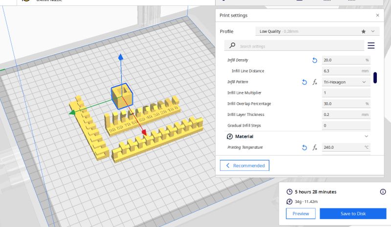
Test Models and Parameters
We printed standard calibration objects to evaluate:
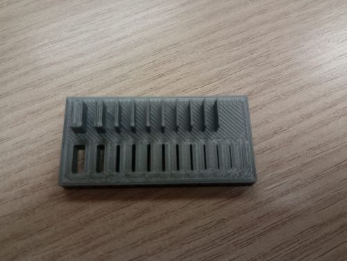
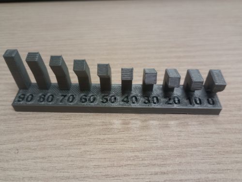
- Overhang test (angles: 30°, 45°, 60°, 70°…).
- Bridge test (increasing span length).
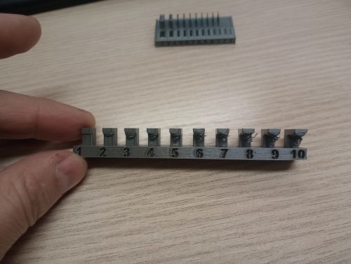
- Clearance and tolerance test (press-fit and sliding-fit holes/pins).
- Wall thickness and text readability (fine details, embossed/engraved text).
- Dimensional accuracy (comparison between CAD dimensions and printed part).
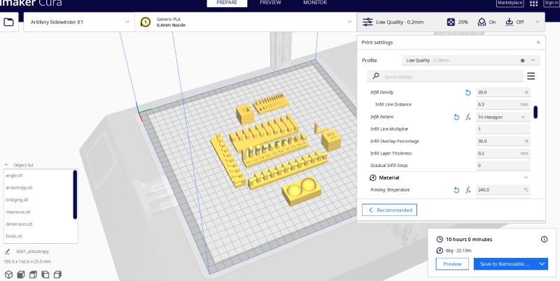
All test parts were sliced using the Artillery and Bambu for test it with the following baseline settings:
- Layer height: 0.2 mm (standard quality).
- Wall/perimeter count: 2–3.
- Infill: 20% (grid/gyroid).
- Nozzle temperature: 240 °C, bed temperature: 60 °C.
- Print speed: 50 mm/s.
I used ULTIMAKER CURA V 5.1.1 for the the Artillery and for the Bambu I used Bambu Studio V2.5.0.66:
Results and Observations
- Overhangs printed cleanly up to about 30º°; beyond that, layers started sagging.
- Bridges up to 2 mm were acceptable; longer spans showed noticeable drooping.
- For clearance tests, a gap of 0.3 mm mm was needed for an easy sliding fit.
- Fine walls below 0.3 mm became fragile or did not print correctly.
Group Reflection – What I Learned
From this characterization I learned that the real design rules of the printer are often more restrictive than the theoretical ones. Knowing the safe overhang angle, the minimum printable clearance and the typical dimensional error helps me design parts that will fit together on the first try, without endless trial and error.
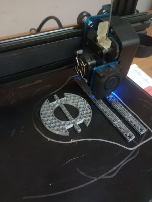
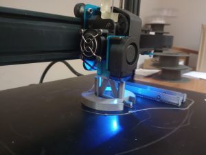
Individual Assignment – 3D Printed Object
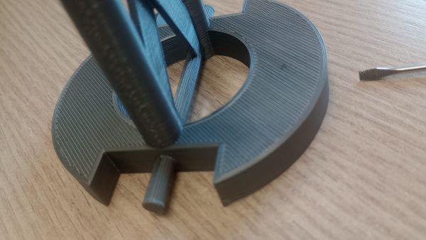
For the individual assignment I designed and printed a small object that cannot be easily made subtractively. The idea is to exploit the strengths of additive manufacturing: internal cavities, complex undercuts and nested geometries.
Concept and Idea
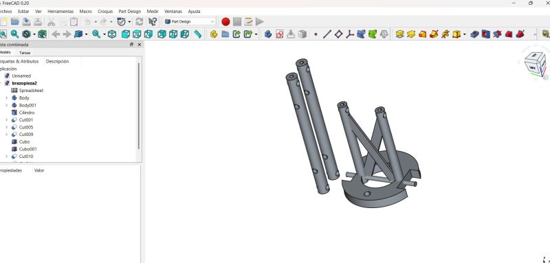
My design is a arm prototype for my robot with moving parts. It includes internal features and overhangs that would be extremely difficult to machine with traditional subtractive methods.
- Overall size: few cm³, respecting Fab lab print time limits.
- Contains internal channels .
- Designed specifically for FDM printing without support but I used with controlled support for testing
Why It Cannot Be Easily Made Subtractively
The key reason this object is suited for 3D printing is the presence of internal volumes and undercuts that cannot be reached by a cutting tool. For example:
- Internal channels: curved paths that change direction in 3D space.
- Complex surfaces that would require multi-axis machining and expensive tooling.
A subtractive process would either require the object to be split into many parts and later assembled, or it would be impossible to machine without special and complex fixtures.
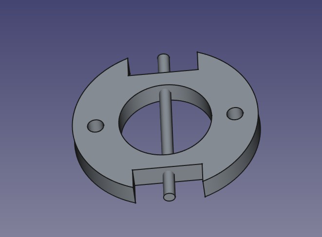
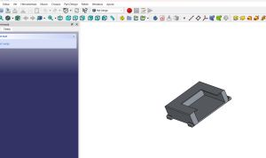
Design Process (CAD)
I designed the part in FreeCAD . My workflow was:
- Sketch basic profiles and dimensions with Freecad
- Use extrusions, revolves and lofts to create the main volumes.
- Add internal features and fillets, respecting the design rules learned in the group test.
- Export the final model as
.stlfor slicing. and then with Ultmaker Cura do the Gcode
Design files:
Slicing and Printing Parameters
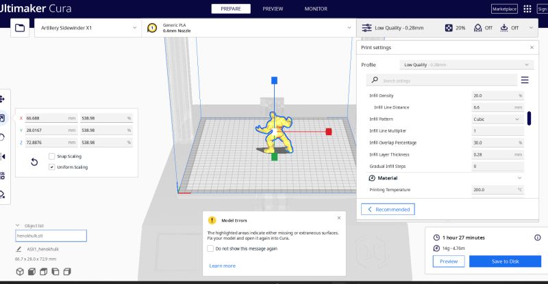
I used Ultimater cura to prepare the print:
- Layer height: 0.2 mm.
- Perimeters: 3.
- Infill: 20% gyroid.
- Material: PLA, nozzle 240 °C, bed 60 °C.
- Supports: enabled
- Estimated print time: 8h minutes.
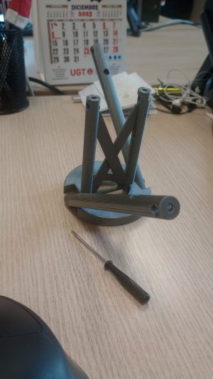
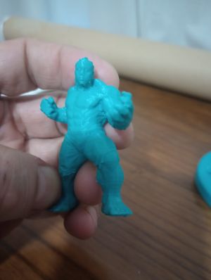
Issues and Iterations
During the first print I observed small defects in the surface . I adjusted temperature and reprinted the object. The second version improved the surface finish and the functionality of the moving parts.
Hero Shots
Individual Assignment – 3D Scanning
The second part of the individual assignment is to 3D scan an object and document the workflow from physical object to a digital mesh.
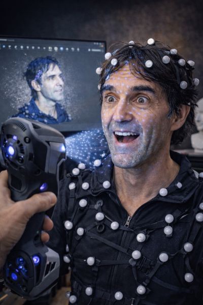
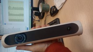
Object and Setup
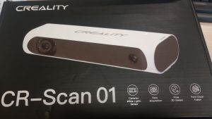
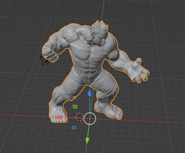
I decided to scan a my son . Afer scan I will use his scan for make a superhero, which are a good test for the scanning process. I will use a old Creality CR Scan 01 to do it and blender for make my favorite super hero I used Cr studio for scan, blender for made my super hero and Cure to print it
Download CR Studio for WindowsScanning Technology Used
I used Creality scan - cr studio - Blender - Cura . The workflow was:
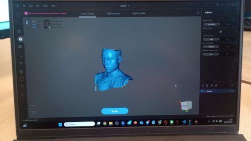
- Scans around Henok from multiple angles.
- Import the data into CR studio.
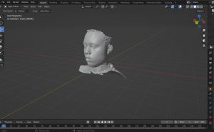
- Generate the 3D mesh for Blender.
- Clean the mesh: remove noise, close holes, simplify where needed. and make a super hero
- Print it with Cura software
The final model was exported as .obj to blender / .stl. for CURA
Scan files:
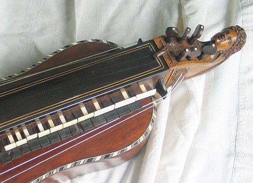
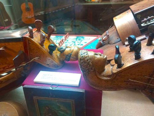
Bonus Pack – Hurdy-Gurdy Ornament and Tuner
This year I started playing the zanfona (hurdy-gurdy) and I bought a new instrument. While researching medieval instruments I noticed that many of them included sculpted figures on the pegbox or body. I decided to add a small personalized figure to my hurdy-gurdy using 3D scanning, design and printing, and combine it with an electronic tuner to give it a modern twist.
Concept
The idea was:
- Scan my wife’s face and use it as a decorative bust on the hurdy-gurdy.
- Hide inside the base a small ATOM / Core2 device acting as a spectrum visualizer and tuner.
- Design the mechanical base in FreeCAD, assemble everything in Blender, and 3D print it on my Bambu printer.
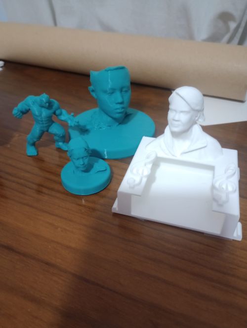
3D Scanning and Bust Creation
First I created a small 3D bust of my wife. Using a photogrammetry workflow (multiple photos around the head), I generated a mesh that I later cleaned and refined:
- Photo capture around the head with uniform lighting.
- Photogrammetry reconstruction to obtain the initial mesh.
- Mesh cleanup and smoothing to make it printable.
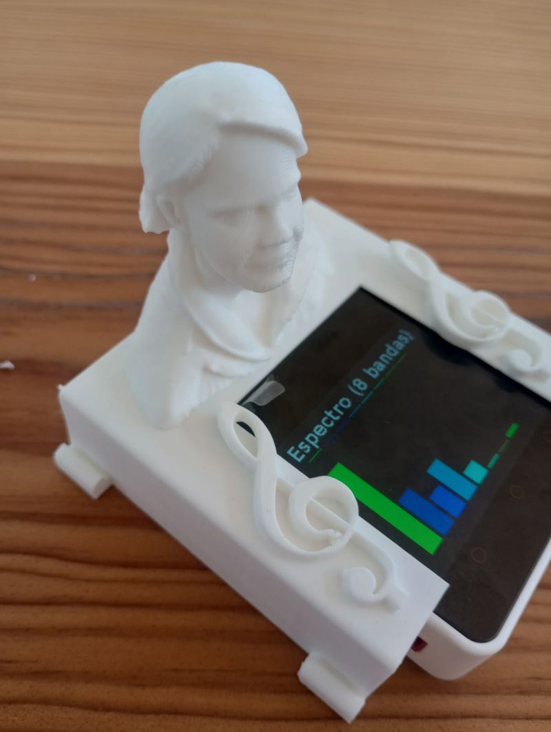
Core2 Spectrum Display and Tuner
To give the ornament a contemporary touch, I programmed an M5Stack Core2 / ATOM device to work as a visual tuner for the hurdy-gurdy:
- The built-in microphone captures the sound of the instrument.
- A MicroPython program computes the frequency spectrum and the fundamental pitch.
- On the touchscreen it shows both a moving spectrum and a simple tuner UI (note name and “too low / in tune / too high”).
This way the decorative figure is not just passive: it also becomes an electronic tool to tune the hurdy-gurdy in G and C.
MicroPython source code:
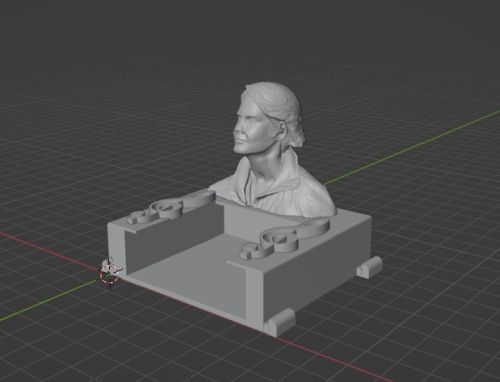
Mechanical Design in FreeCAD and Assembly in Blender
Using what I learned in previous weeks, I designed the base in FreeCAD so that:
- The Core2 fits snugly inside the base.
- There is a cable path and space for buttons if needed.
- The bust sits on top with a secure mechanical joint.
After exporting the individual parts, I used Blender to:
- Combine the bust + base into a single assembly.
- Check proportions and overall aesthetics with the hurdy-gurdy.
- Export the final merged model as
.stlfor printing.
Design files:
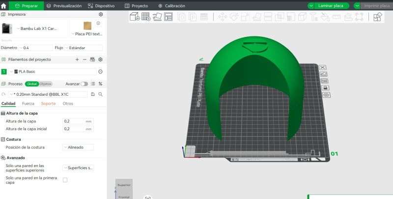
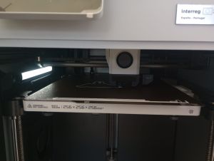
3D Printing on Bambu
The final model was printed on a Bambu 3D printer using:
- Material: PLA.
- Layer height: 0.16–0.20 mm.
- Infill: 15–20% (gyroid).
- Supports only under the bust overhangs.
Final Result – Video
In this video you can see the complete system: the printed bust and base mounted on the hurdy-gurdy, with the Core2 drawing the spectrum and acting as a tuner while I play. (I will paint it as soon as possible)
Summary and Reflection
This week helped me understand both sides of digital fabrication: creating geometry from scratch (CAD + 3D printing) and capturing geometry from the real world (3D scanning).
From the 3D printer characterization I learned realistic design rules for our machines: safe overhang angles, minimum clearances, typical dimensional errors and how slicing parameters affect quality. This will directly influence how I design functional parts in the rest of the Fab Academy.
Designing an object that cannot be easily made subtractively forced me to think in an additive way: internal volumes, captive parts and complex shapes become natural when you print layer by layer.
Finally, with 3D scanning I saw how physical objects can be brought back into the digital world, but also that the process is not perfect: there are limitations in terms of texture, reflectivity and resolution. Combining scanning with CAD editing opens interesting workflows for reverse engineering and customization.