Week 04 – Embedded Programming
This week is focused on Embedded Programming: comparing development workflows/toolchains for different embedded architectures, browsing microcontroller datasheets, and writing/testing programs that interact with local inputs/outputs and communicate remotely (wired or wireless).
On this page I document:
- The group assignment: toolchains + workflows on two different MCU families.
- My datasheet browsing (RP2040 + ESP32-PICO) and the key sections used.
- My individual embedded program: local I/O + remote communication.
- The programming process, source code, and hero shots.
Assignment and Learning Outcomes
The weekly assignment is:
- Group assignment:
- Demonstrate and compare the toolchains and development workflows for available embedded architectures.
- Document your work to the group work page and reflect on your individual page what you learned.
- Individual assignment:
- Browse through the datasheet for a microcontroller.
- Write and test a program for an embedded system using a microcontroller to interact (local input &/or output devices) and communicate (remote wired or wireless connections).
The learning outcomes are:
- Implement programming protocols.
- Program a board to interact and communicate.
- Describe and compare embedded development workflows.
Checklist
In this page I answer the required questions:
- Linked to the group assignment page.
- Browsed and documented info from a microcontroller datasheet.
- Programmed a board to interact (local I/O) and communicate (wired/wireless).
- Described the programming process(es) used.
- Included my source code.
- Included hero shot(s).
You can see the group documentation here:
Group Assignment – Toolchains and Workflows Comparison
The Fab Academy FAQ clarifies that this group assignment is not theoretical: we must physically program devices from at least two different MCU families using different toolchains.
Boards used in our group
- Seeed Studio XIAO RP2040 – MCU family: RP2040 (Dual-core ARM Cortex-M0+)
- M5Stack ATOM (ESP32-PICO) – MCU family: ESP32 (Dual-core Xtensa LX6)
Toolchains used
We intentionally used different development environments to compare workflows:
- XIAO RP2040 → Arduino IDE (RP2040 Arduino core)
- ATOM ESP32-PICO → ESP-IDF (official Espressif framework) or UiFlow2
Individual Assignment 1 – Microcontroller XIAO RP2040
Workflow A – XIAO RP2040 with Arduino IDE
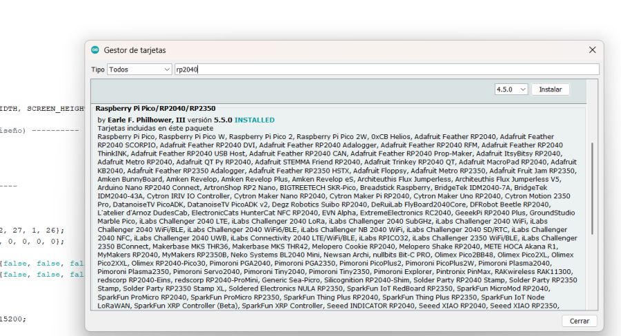
- Install Arduino IDE and add RP2040 board support (Seeed / RP2040 core).
- Select board: Seeed XIAO RP2040 and correct USB port.
- Write sketch (.ino) using Arduino APIs.
- Compile & Upload (UF2/bootloader workflow handled by core).
- Debug/monitor using Serial Monitor (USB CDC serial).
XIAO RP2040 – Development Process
The first step was to collect the official documentation from the manufacturer. I used the Seeed Studio product wiki to download the datasheet-related information, understand the board features, and review the recommended programming workflow:
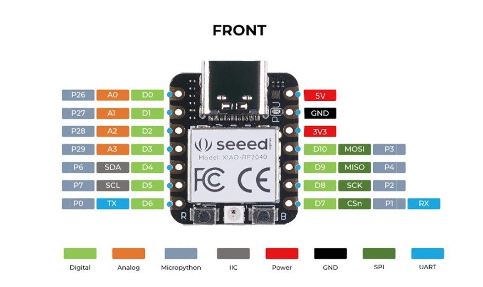
After that, I analyzed the board specifications and the connection diagram (pinout / schematic) to identify the available GPIOs, power rails, and the pins required for my project. Here I include a reference image of the board connections:
As a starting point, I downloaded an initial test program from Quentin Bolsee’s repository. This example helped me validate my toolchain and confirm that the board was correctly detected and programmable.
Finally, I modified the original program to adapt it to my own setup and requirements. I changed the code structure and parameters and now we can view all buttons, for more thingsI add UART comunication for the button to send the data other devices
Source Code
You can download the Arduino source code used in this assignment here:
Arduino · test_touch_RP2040_V3.ino Show code
#include
#include
#include
#include

// ---------- OLED ----------
#define SCREEN_WIDTH 128
#define SCREEN_HEIGHT 64
#define SCREEN_ADDRESS 0x3C

Adafruit_SSD1306 display(SCREEN_WIDTH, SCREEN_HEIGHT, &Wire, -1, 1700000UL, 1700000UL);

// ---------- RGB LED (según tu diseño) ----------
#define PIN_RED 17
#define PIN_GREEN 16
#define PIN_BLUE 25

// ---------- Touch config ----------
#define N_TOUCH 6
#define THRESHOLD 6

int touch_pins[N_TOUCH] = {3, 4, 2, 27, 1, 26};
int touch_values[N_TOUCH] = {0, 0, 0, 0, 0, 0};

bool pin_touched_now[N_TOUCH]  = {false, false, false, false, false, false};
bool pin_touched_past[N_TOUCH] = {false, false, false, false, false, false};

// ---------- UART ----------
#define UART_PORT Serial1
const unsigned long UART_BAUD = 115200;

// Envía el estado de los 6 botones como "B:010101\n"
void sendButtonsUART() {
  UART_PORT.print("B:");
  for (int i = 0; i < N_TOUCH; i++) {
    UART_PORT.print(pin_touched_now[i] ? '1' : '0');
  }
  UART_PORT.print('\n');
}

// ---------- Touch reading ----------
void update_touch() {
  int t;
  int t_max = 200;
  int p;

  for (int i = 0; i < N_TOUCH; i++) {
    p = touch_pins[i];

    pinMode(p, OUTPUT);
    digitalWriteFast(p, LOW);

    delayMicroseconds(25);

    pinMode(p, INPUT_PULLUP);

    t = 0;
    while (!digitalReadFast(p) && t < t_max) {
      t++;
    }
    touch_values[i] = t;

    pin_touched_past[i] = pin_touched_now[i];
    pin_touched_now[i]  = (touch_values[i] > THRESHOLD);
  }
}

void print_touch() {
  char print_buffer[30];
  for (int i = 0; i < N_TOUCH; i++) {
    sprintf(print_buffer, "%4d ", touch_values[i]);
    Serial.print(print_buffer);
  }
  Serial.println();
}

// ---------- Simple UI helpers ----------
const int TITLE_Y = 0;      // zona amarilla (bicolor físico)
const int STATE_Y = 16;     // debajo (zona azul)
const int COL_W   = 21;     // 6 columnas en 128px
const int X0      = 0;
const int LINE_H  = 8;

void drawTitles() {
  // limpia solo la banda superior
  display.fillRect(0, 0, 128, 16, SSD1306_BLACK);

  for (int i = 0; i < N_TOUCH; i++) {
    int x = X0 + i * COL_W;
    display.setCursor(x, TITLE_Y);
    display.print("B-");
    display.print(i + 1);
  }
}

void drawState(int idx, bool on) {
  int x = X0 + idx * COL_W;

  // limpia SOLO el hueco del estado
  display.fillRect(x, STATE_Y, COL_W, LINE_H, SSD1306_BLACK);

  display.setCursor(x, STATE_Y);
  display.print(on ? "ON" : "OFF");
}

void setup() {
  Serial.begin(115200);
  delay(50);

  // OLED
  display.begin(SSD1306_SWITCHCAPVCC, SCREEN_ADDRESS);
  display.clearDisplay();
  display.setTextSize(1);
  display.setTextColor(SSD1306_WHITE);

  // LED
  pinMode(PIN_RED, OUTPUT);
  pinMode(PIN_GREEN, OUTPUT);
  pinMode(PIN_BLUE, OUTPUT);
  digitalWrite(PIN_RED, HIGH);
  digitalWrite(PIN_GREEN, HIGH);
  digitalWrite(PIN_BLUE, HIGH);

  // Splash
  display.setCursor(28, 25);
  display.print("Hello Oscar");
  display.display();
  delay(1500);

  display.clearDisplay();
  display.setCursor(20, 25);
  display.print("button control");
  display.display();
  delay(800);

  // UART
  UART_PORT.begin(UART_BAUD);

  // UI inicial
  display.clearDisplay();
  drawTitles();
  for (int i = 0; i < N_TOUCH; i++) {
    drawState(i, false);
  }
  display.display();
}

void loop() {
  update_touch();

  bool changed = false;

  // si algún botón cambió, actualiza OLED + manda UART
  for (int i = 0; i < N_TOUCH; i++) {
    if (pin_touched_now[i] != pin_touched_past[i]) {
      changed = true;
      drawState(i, pin_touched_now[i]);
    }
  }

  if (changed) {
    display.display();
    sendButtonsUART();

    // feedback LED (opcional): enciende verde si hay al menos uno ON
    bool anyOn = false;
    for (int i = 0; i < N_TOUCH; i++) anyOn |= pin_touched_now[i];
    digitalWrite(PIN_GREEN, anyOn ? LOW : HIGH);
  }

  // Debug opcional
  // print_touch();

  delay(20);
}
Final Result – Video Demonstration
The following video shows the final working system: XIAO RP2040 reading the touch buttons and sending the state via UART to the ESP32, which processes the received data.
Individual assignment 2 M5Stack ATOM (ESP32-PICO) – Development Process
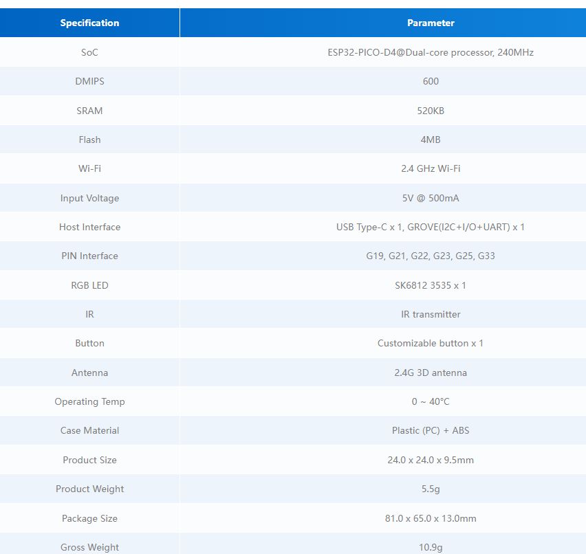
To begin working with the ATOM board, I first consulted the official manufacturer documentation in order to obtain technical specifications, pin configuration details, and recommended programming workflows.
The official documentation can be found at the following link:
From this page, I reviewed the hardware specifications, including the ESP32-PICO-D4 microcontroller architecture, integrated WiFi and Bluetooth capabilities, available GPIOs, power characteristics, and communication interfaces.
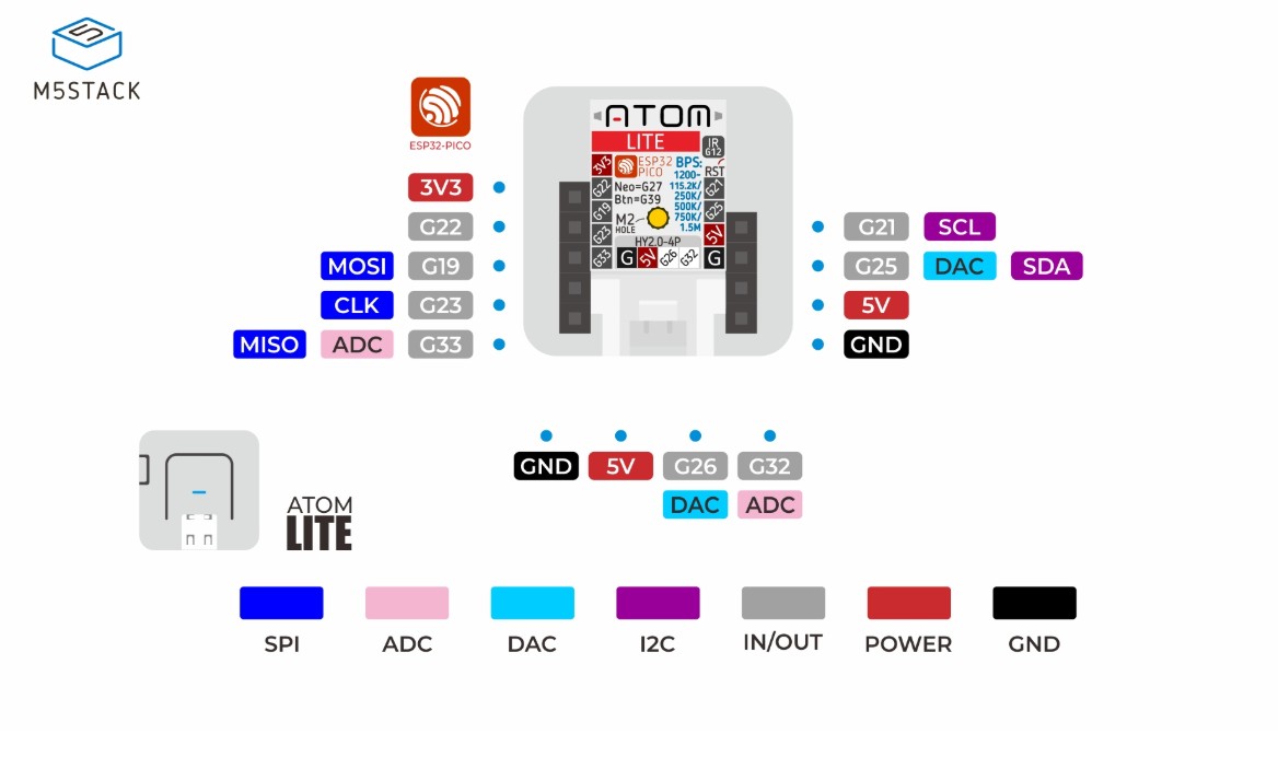
I also analyzed the board pinout to correctly identify the pins required for UART communication and external connections. The following image shows the ATOM pin configuration used in this project:
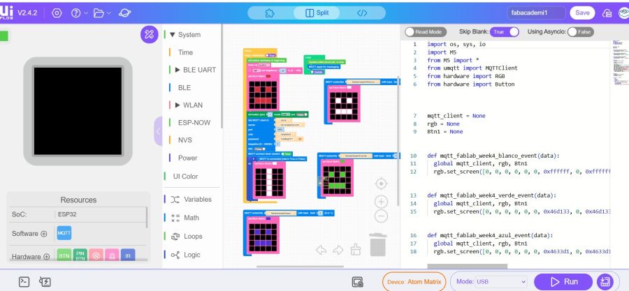
In addition to using the Arduino framework during development, I decided to explore a different programming environment by switching to UiFlow2. This allowed me to compare multiple development platforms and better understand how different toolchains interact with the ESP32 architecture.
Working with UiFlow2 provided a more visual and structured programming approach, while still allowing low-level control of the ESP32 hardware. This comparison helped me better understand the flexibility of the ESP32 ecosystem and the differences between Arduino-based and alternative development workflows. Additionally, this programming environment translates into MicroPython, allowing users to easily observe and compare both programming systems.
I used the tutorials from UiFlow2 Web IDE: Instaling the M5Burning for windows Register in Register an M5Stack Community account
M5Stack ATOM Matrix — MicroPython + MQTT + MIT App Inventor
Fab Academy Documentation
Overview ATOM
For this assignment I worked with the M5Stack ATOM Matrix (ESP32 + 5x5 RGB LED matrix). The goal was to create a small IoT device that connects to WiFi, establishes an MQTT connection, and can be controlled remotely from a mobile application.
The device provides visual feedback using the LED matrix:
- Red face → Device powered and program started
- White vertical bar → Successful MQTT connection
- Color changes via mobile app → Remote control confirmed
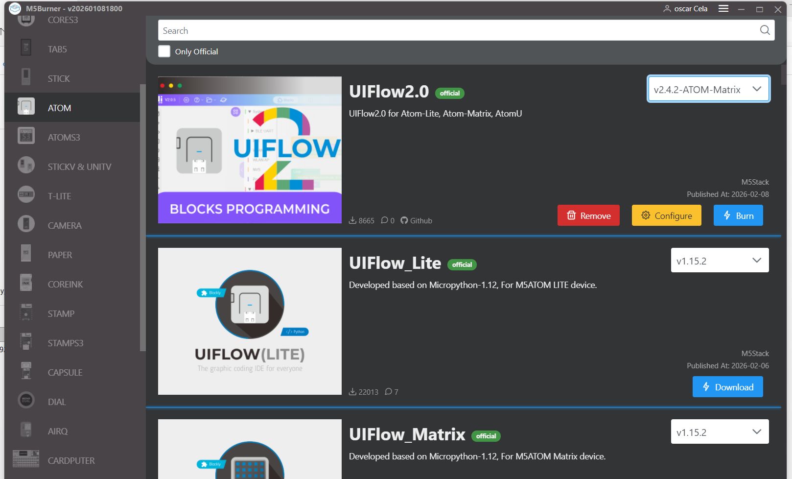
Firmware Installation (UIFlow2)
Initially, the ATOM Matrix was flashed using M5Burner with the official UIFlow2 firmware for ATOM devices.
This step is required because the UIFlow2 firmware provides the M5Stack-specific MicroPython modules needed to control the LED matrix and hardware.
Steps followed:- Download and install M5Burner
- Select ATOM Matrix device
- Choose UIFlow2 firmware
- Flash the firmware via USB
- Reboot and verify MicroPython environment
MicroPython Development
After flashing UIFlow2, I developed a MicroPython program that:
- Initializes the ATOM Matrix
- Displays a red face on boot
- Connects to my phone’s WiFi hotspot
- Connects to my MQTT server
- Displays a white bar once MQTT connection is successful
- Subscribes to a topic to receive color commands
The LED matrix acts as a real-time status indicator, eliminating the need for constant serial debugging.
Source Code
The complete MicroPython source code can be downloaded here:
Download MicroPython Program (main.py)
micropyton · micropyton.py Show code
import os, sys, io
import M5
from M5 import *
from umqtt import MQTTClient
from hardware import RGB
from hardware import Button


mqtt_client = None
rgb = None
Btn1 = None


def mqtt_fablab_week4_blanco_event(data):
  global mqtt_client, rgb, Btn1
  rgb.set_screen([0, 0, 0, 0, 0, 0, 0xffffff, 0, 0xffffff, 0, 0, 0, 0, 0, 0, 0, 0xffffff, 0xffffff, 0xffffff, 0, 0, 0, 0, 0, 0])


def mqtt_fablab_week4_verde_event(data):
  global mqtt_client, rgb, Btn1
  rgb.set_screen([0, 0, 0, 0, 0, 0, 0x46d133, 0, 0x46d133, 0, 0, 0, 0, 0, 0, 0, 0x46d133, 0x46d133, 0x46d133, 0, 0, 0, 0, 0, 0])


def mqtt_fablab_week4_azul_event(data):
  global mqtt_client, rgb, Btn1
  rgb.set_screen([0, 0, 0, 0, 0, 0, 0x4633d1, 0, 0x4633d1, 0, 0, 0, 0, 0, 0, 0, 0x4633d1, 0x4633d1, 0x4633d1, 0, 0, 0, 0, 0, 0])


def setup():
  global mqtt_client, rgb, Btn1

  M5.begin()
  Widgets.fillScreen(0x000000)

  rgb = RGB()
  rgb.set_screen([0, 0, 0, 0, 0, 0, 0, 0, 0, 0, 0, 0, 0, 0, 0, 0, 0, 0, 0, 0, 0, 0, 0, 0, 0])
  rgb.set_brightness(20)
  rgb.set_screen([0, 0, 0, 0, 0, 0, 0xcd3232, 0, 0xcd3232, 0, 0, 0, 0, 0, 0, 0, 0xcd3232, 0xcd3232, 0xcd3232, 0, 0, 0, 0, 0, 0])
  Btn1 = Button(1, active_low=True, pullup_active=False)
  mqtt_client = MQTTClient('oscar', 'xxxxxxxx', port=1883, user='xxxxxxxx', password='xxxxxxxx', keepalive=0)
  mqtt_client.connect(clean_session=True)
  mqtt_client.subscribe('fablab/week4/blanco', mqtt_fablab_week4_blanco_event, qos=0)
  mqtt_client.subscribe('fablab/week4/verde', mqtt_fablab_week4_verde_event, qos=0)
  mqtt_client.subscribe('fablab/week4/azul', mqtt_fablab_week4_azul_event, qos=0)
  if mqtt_client.isconnected():
    rgb.set_screen([0, 0, 0xffffff, 0, 0, 0, 0, 0xffffff, 0, 0, 0, 0, 0xffffff, 0, 0, 0, 0, 0xffffff, 0, 0, 0, 0, 0xffffff, 0, 0])


def loop():
  global mqtt_client, rgb, Btn1
  M5.update()
  mqtt_client.check_msg()


if __name__ == '__main__':
  try:
    setup()
    while True:
      loop()
  except (Exception, KeyboardInterrupt) as e:
    try:
      from utility import print_error_msg
      print_error_msg(e)
    except ImportError:
      print("please update to latest firmware")
MQTT Communication
The ATOM Matrix connects to my MQTT broker running on a remote server. The communication flow is:
- Device connects to WiFi hotspot
- Device connects to MQTT broker (port 1883)
- Device subscribes to a command topic
- Mobile app publishes color commands
- Device updates LED face color accordingly
MIT App Inventor Mobile Application
To remotely control the device, I created a simple Android application using MIT App Inventor.
The app includes:
- Two buttons
- Each button publishes a different color command via MQTT
App Blocks
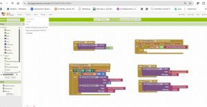
When a button is pressed, the app publishes a text message to the MQTT topic. The ATOM Matrix receives the message and updates the face color.
---Results
- Boot → Red face displayed
- WiFi connection → automatic via hotspot
- MQTT connection → white bar displayed
- App control → face color changes instantly
7. Demonstration Video
---Conclusions
This project demonstrates:
- Firmware flashing using M5Burner
- MicroPython development on ESP32-based hardware
- WiFi and MQTT connectivity
- Mobile IoT control via MIT App Inventor
The ATOM Matrix provides an excellent compact platform for IoT experimentation, combining visual feedback, WiFi connectivity, and simple user interaction.
Architectural and Workflow Comparison
| Category | Seeed Studio XIAO RP2040 | M5Stack ATOM ESP32-PICO |
|---|---|---|
| Microcontroller Family | Raspberry Pi RP2040 | Espressif ESP32-PICO-D4 |
| CPU Architecture | Dual-core ARM Cortex-M0+ (ARMv6-M) | Dual-core Xtensa LX6 |
| Wireless Connectivity | Not integrated (requires external module) | Integrated WiFi 802.11 b/g/n + Bluetooth |
| Development Environment | Arduino IDE (RP2040 core) | ESP-IDF / PlatformIO / Arduino core |
| Development Workflow | Sketch-based, simplified abstraction layer | Project-based structure with configurable build system |
| Debugging Approach | USB Serial (CDC) monitoring | Serial logging, FreeRTOS logs, optional JTAG debugging |
| Typical Use Case | Deterministic embedded control and fast prototyping | Connected IoT applications and network-enabled systems |
Group reflection (what I learned)
The Arduino workflow on RP2040 is very fast for prototyping and simple I/O tests. On the other hand, ESP-IDF/PlatformIO for ESP32 feels more “professional” and scalable, especially when the project needs wireless connectivity and more advanced configuration. Both approaches are useful depending on the project requirements.
Individual Assignment – Datasheet Browsing
To support my programming decisions, I browsed the datasheets of the two microcontrollers used this week: RP2040 and ESP32-PICO. I focused on sections related to GPIO, electrical limits, communication peripherals, and boot/programming modes.
RP2040 – key datasheet items I used
- GPIO / Pin functions: mapping pins to GPIO and alternate functions (UART, I2C, SPI, PWM).
- USB: native USB device support (useful for Serial over USB).
- PIO (Programmable I/O): special feature of RP2040 for custom protocols (not required here, but important to know).
- Clocks: default clocking and implications for timing/baud rate.
- Memory: SRAM size and external flash usage.
- Boot / UF2: BOOTSEL behavior and firmware upload workflow.
ESP32-PICO – key datasheet items I used
- WiFi/Bluetooth: integrated radio and typical usage scenarios for wireless communication.
- GPIO matrix: flexible assignment of peripheral signals to pins.
- Power / RF notes: stable power supply considerations when using WiFi.
- Boot mode: strapping pins and flashing via USB-serial interface.
Individual Assignment – Program: Local I/O + Remote Communication
For the individual program I created a small embedded system using both boards: the XIAO RP2040 handles the local interaction (button + LED), ATOM ESP32-PICO uses WiFI and MQTT comunicactions.
This demonstrates:
- Local input/output: button toggles LED on the RP2040.
- Remote wireless communication: ESP32 recibe data from app
Hardware setup
- XIAO RP2040: reads button + controls LED.
- ATOM ESP32-PICO: receives MQTT message
- Flashed a simple Serial test on each board to verify toolchains and ports.
- Implemented button + LED logic on RP2040 with debounce.
- On ESP32, read MQTT
- Pressing the button toggles the LED on the RP2040.
- RP2040 sends
LED=1/LED=0through UART. - ESP32 connects to WiFi and MQTT and change color from a APPINVENTOR
Note: RP2040 GPIO is 3.3V and ESP32 GPIO is also 3.3V, so UART level shifting is typically not needed.
Programming process
Results
Summary and Reflection
This week connected datasheets, toolchains, and real hardware testing. Comparing two MCU families (RP2040 vs ESP32) made it clear how architecture and integrated peripherals change the workflow: RP2040 is excellent for deterministic microcontroller tasks and fast prototyping, while ESP32 is extremely convenient for connected applications because WiFi/BLE and FreeRTOS are built-in.
My individual system demonstrates a complete embedded pipeline: sense (button) → act (LED) → communicate (UART + WiFi+ MQTT). Debugging with serial logs on both boards helped me verify behavior step by step and avoid “black-box” errors.