Week 03 – Computer-Controlled Cutting
This is the third week of the Fab Academy and it is focused on Computer-Controlled Cutting. The work is divided into a group assignment (lab safety and laser cutter characterization) and an individual assignment (parametric construction kit and vinyl cutting).
On this page I document:
- Our lab safety training and the characterization of the laser cutter.
- The design and fabrication of a parametric press-fit construction kit in FreeCAD, accounting for the kerf.
- The process of cutting a yacht captain symbol on the vinyl cutter using an SVG designed in Inkscape.
- Links to my original design files and pics of the results.
Assignment and Learning Outcomes
The weekly assignment is:
- Group assignment:
- Do your lab's safety training.
- Characterize your laser cutter's focus, power, speed, rate, kerf, joint clearance and types.
- Document your work on the group work page and reflect on your individual page what you learned.
- Individual assignment:
- Design, lasercut, and document a parametric construction kit, accounting for the laser cutter kerf.
- Cut something on the vinyl cutter.
The learning outcomes are:
- Demonstrate and describe parametric 2D modelling processes.
- Identify and explain processes involved in using the laser cutter.
- Develop, evaluate and construct a parametric construction kit.
- Identify and explain processes involved in using the vinyl cutter.
Checklist
In this page I answer the required questions:
- Linked to the group assignment page.
- Reflected on my individual page what I learned from the lab safety training.
- Explained how I created my parametric design in FreeCAD.
- Documented how I made my press-fit construction kit.
- Documented how I made the yacht captain symbol with the vinyl cutter.
- Included my original design files (FreeCAD and SVG).
- Included hero shots of the results.
You can see the group documentation here:
Group Assignment – Safety and Laser Cutter Characterization
Lab safety training
Before using the laser cutter and the vinyl cutter, we did the lab safety training with our instructor. The main points were:
- General Fab Lab rules (access, supervision, emergency exits, fire extinguisher location).
- Specific safety procedures for the laser cutter (supervision during cutting, ventilation, material list).
- Allowed and forbidden materials (no PVC or unknown plastics, only tested and approved materials).
- Use of personal protective equipment when necessary (safety glasses, gloves for handling material edges).
- Emergency stop button and procedure in case of fire or smoke inside the machine.
Personally, this session helped me to become more aware of the importance of never leaving the laser cutter unattended, checking materials carefully and keeping the bed clean to avoid flare-ups and reflections.
Laser cutter characterization
In the group we characterized the behavior of our laser cutter to understand the relationship between power, speed, frequency (rate), and the resulting kerf and joint clearance.
Focus test
First we performed a focus ramp test:
- We placed a board of the material used for the kit (for example 3 mm plywood / 3 mm acrylic).
- We cut a sloped “ramp” where the Z-height varies along the X axis.
- We examined the cut and engraving width to find the position with the thinnest and cleanest line.
- We recorded the optimal focus distance in the machine settings and as a physical gauge.
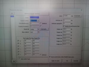
Power and speed test grid
Then we created a test grid to explore different combinations of power and speed:
- We designed a matrix of small squares in vector software (e.g. Inkscape).
- Each row had a different power percentage and each column a different speed.
- We cut and engraved the grid on the same material used for the kit.
- We noted which combinations:
- cleanly cut through,
- barely cut / required multiple passes,
- burned or produced too much char.
From this grid we selected the default cutting parameters for our construction kit material (for example: 3 mm plywood → 50% power, 8 mm/s speed, 1 pass).
Kerf measurement
To measure the kerf (material removed by the laser beam), we cut a precise test piece:
- We designed a 20 mm × 20 mm square and a frame around it.
- After cutting, we measured the resulting square and the gap using a caliper.
- The kerf is approximately half of the difference between the nominal dimension and the measured piece.
For our settings and material, we obtained a kerf of 0.127 mm (this value is used later in the parametric model).
Joint clearance tests
Finally, we tested different slot widths to find the best press-fit:
- We cut a series of comb-like test pieces with slot widths of: material thickness −0.20 mm, −0.10 mm, 0, +0.10 mm.
- We tried to assemble them by hand and evaluated the fit:
- Too tight → difficult to insert, risk of breaking.
- Too loose → falls apart when lifted.
- Good press-fit → pieces hold firmly but can be assembled and disassembled.
The best result for our 3 mm material was around material thickness − kerf, which we later used in the FreeCAD parametric model.
Individual Assignment – Parametric Press-Fit Construction Kit
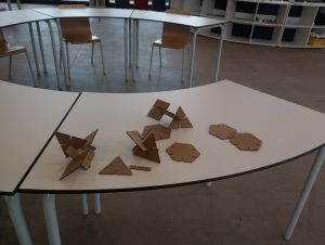
For the individual part of the assignment I designed and fabricated a parametric press-fit construction kit based on polygonal pieces. The kit is composed of two parametric polygon shapes modelled in FreeCAD, each with slots that allow multiple assembly combinations.
Concept and requirements
Following the Fab Academy requirements, my construction kit:
- Uses parametric dimensions (material thickness, kerf, slot width...).
- Can be assembled in many different ways (not just a simple finger-joint box).
- Does not require adhesives; pieces stay together by press-fit.
- Does not fall apart when lifted.
The idea is to build structures by combining:
- A regular polygon piece (for example hexagon) with slots on each side.
- Another polygonal piece with radial slots that can connect to the edges of the first one.
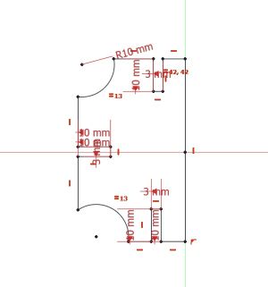
Parametric design in FreeCAD
I created the two polygon pieces as parametric models in FreeCAD. The main steps were:
- Create a new document and switch to the Part Design workbench.
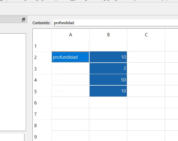
- Create a Spreadsheet (or use Expressions) with the main parameters:
material_thickness(e.g. 3 mm).kerf(e.g. 0.15 mm from our group test).slot_width = material_thickness - kerf.- Polygon radius / side length.
- Slot length and slot offset from edges.
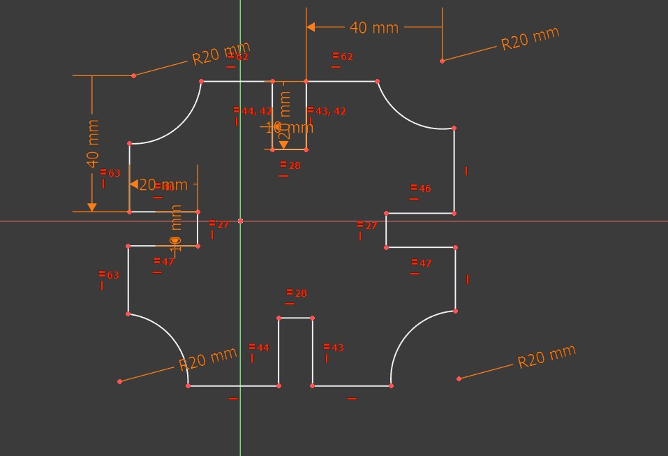
- Create a Sketch of the polygon on the XY plane and fully constrain it.
- Add rectangles for the slots and constrain their width to
slot_widthand length to the parameter defined in the spreadsheet. - Use Pad to give a small thickness for visualization (not relevant for 2D cutting but useful to see the part).
The advantage of this approach is that if I change the material thickness or want a different kerf, I only need to update the parameters and the entire geometry adapts automatically.
Parametric design in Grasshopper
The polygon pieces were designed using a parametric workflow in Rhino with Grasshopper. Instead of drawing fixed geometries, the design was controlled through a set of adjustable parameters.
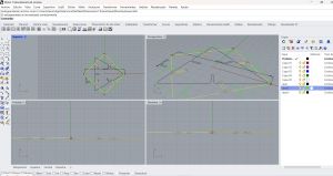
- Create a new document in Rhino (units in millimeters) and open Grasshopper.
- Define the main parameters using Number Sliders:
material_thickness(e.g. 2.5 mm).kerf(measured during group characterization).slot_width = material_thickness - kerf.- Overall size, number of polygon sides, and slot depth.
- Generate the base polygon parametrically and place the slots using geometric transformations and array components.
- Apply boolean operations to subtract the slots from the main geometry.
- Add small fillets to the internal corners to reduce stress and improve assembly.
- Bake the final 2D curves into Rhino on a dedicated laser-cutting layer.
This parametric approach made it easy to adjust the design for different materials or kerf values, ensuring accurate press-fit joints without redrawing the geometry.
Export for laser cutting
Once the sketches were fully constrained and parametric, I exported them for the laser cutter:
- Switched to the TechDraw or Draft workbench and created a 2D view of each sketch.
- Exported the geometry as DXF and/or SVG.
- Opened the file in Inkscape to check scale and line settings (hairline / correct stroke width).
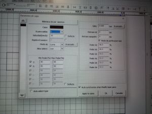
- Sent the final vectors to the laser cutter software with the parameters obtained in the group test.
You can download my original parametric design files here:
- dxf file – polygon piece 1 (.FCStd)
- dfx file – polygon piece 2 (.FCStd)
- dfx file – layout for laser cutting
- dfx file – poligon 3
- Grasshopper file
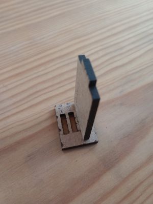
Laser cutting and assembly
For this assignment, instead of creating a new design from scratch, I followed the Grasshopper tutorial and parametric design developed by Jesús López, available at: Fab Academy – Parametric Design with Grasshopper .
This Grasshopper definition provides a very intuitive way to modify the geometry, number of pieces, and overall scale of the model by simply adjusting a set of parameters. This made it especially suitable for understanding the relationship between material thickness, kerf, and joint design.
Once the desired configuration was defined in Grasshopper, the parts were exported and prepared for laser cutting using the parameters previously determined during machine characterization. After cutting, the edges were cleaned and the assembly process was carried out.
- The parametric definition automatically adapts the slot dimensions to the material thickness, allowing a firm press-fit without the need for glue.
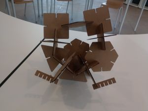
- The same set of pieces can be rearranged to create both flat and three-dimensional structures by changing their orientation during assembly.
- Thanks to the parametric approach, the kit can be easily resized or modified and disassembled and reassembled without damaging the parts.
- The previous links correspond to the parametric design work developed in Rhino using Grasshopper.
This exercise clearly demonstrates the advantages of parametric design in digital fabrication, as it allows fast iteration and precise control of tolerances, which is essential for achieving reliable press-fit joints in laser-cut assemblies.
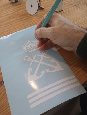
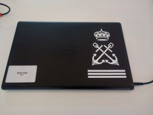
Vinyl Cutting – Yacht Captain Symbol
For the vinyl cutting part of the assignment I used a design with the yacht captain symbol, prepared in Inkscape and cut on the vinyl cutter.
Design in Inkscape
I worked in Inkscape to create/prepare the yacht captain symbol:
- Created a new document with units in mm.
- Imported or redrew the yacht captain symbol using basic shapes and path operations.
- Converted all strokes to paths (Path → Stroke to Path) to ensure the cutter follows the correct contours.
- Checked that all shapes were closed paths and removed fills when necessary, keeping only the outlines.
- Scaled the symbol to the final size (for example, 80 mm wide) and positioned it inside the page area.
I based the design on a public reference of a captain symbol and redrew it in Inkscape, acknowledging the original source in my notes.
You can download the SVG file used for vinyl cutting here:
Vinyl cutter workflow
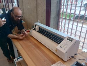
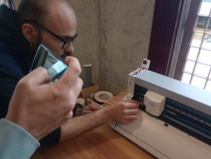
The process on the vinyl cutter was as follows:
- Loaded a roll of adhesive vinyl (for example, dark blue) into the machine and aligned it with the rollers.
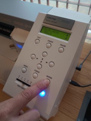
- Set the origin point and performed a test cut to adjust blade depth, speed and force.
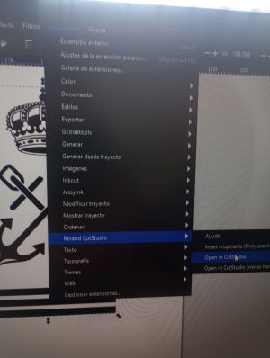
- Imported the SVG into the vinyl cutter software and set the correct scale and orientation.
- Selected cut-only mode (no pen) and sent the job to the machine.
- After cutting, I carefully weeded the excess vinyl using tweezers.
- Applied transfer tape on top of the design and then transferred it to the final surface (for example, a laptop or a toolbox).
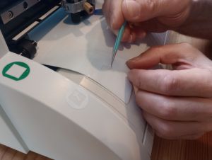
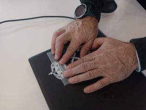
Although it is not compulsory to document the exact vinyl cutter settings, experimenting with speed and force helped me to get clean cuts without cutting through the backing paper.
Summary and Reflection
During this week, I moved from a general understanding of laser cutting to a more quantitative and controlled approach, taking into account key parameters such as focus distance, power, speed, kerf, and joint clearance. The group machine characterization was essential to obtain reliable and repeatable results.
In addition to the initial parametric work, I explored the use of Rhino in combination with Grasshopper for the design of press-fit structures. By following an existing Grasshopper definition, I was able to understand how parametric relationships can be used to control geometry, number of elements, and overall scale in a very intuitive way.
Using Grasshopper allowed me to quickly modify parameters such as material thickness, slot width, and size, and immediately see the impact on the final design. This approach proved to be especially useful for laser cutting, where small variations in kerf or material can significantly affect the quality of press-fit joints.
The vinyl cutting exercise highlighted the differences between preparing files for laser cutting and vinyl cutting, particularly regarding stroke handling, closed paths, and the importance of proper weeding and transfer techniques to achieve a clean result.
Overall, this assignment successfully connected parametric digital design, machine characterization, and physical fabrication. Working with tools such as FreeCAD and Rhino + Grasshopper reinforced the idea that a well-defined parametric model and good documentation greatly reduce trial and error and make it easier to adapt designs to different materials and machines.