Week 02 – Computer-Aided Design / Image and Video Compression
This is the second week of the Fab Academy, which includes two main tasks: Computer-Aided Design and Image and Video Compression. The goal is to model a possible final project, document the design process in 2D and 3D, compress media files, and upload both documentation and source files to the class archive.
On this page I document:
- 2D design using raster (Paint) and vector (Inkscape) tools.
- 3D modelling using Rhino, FreeCAD and Blender.
- A first sketch of my final project, exported as
.FCStdand.stl. - Image compression with IrfanView 64 and video compression with HandBrake 64.
Assignment and Learning Outcomes
The assignment for this week is to:
- Model (raster, vector, 2D, 3D, render, animate, simulate, …) a possible final project.
- Compress images and videos used in the documentation.
- Post a description with the design files on the class page.
The learning outcomes are:
- Evaluate and select 2D and 3D software.
- Demonstrate and describe processes used in modelling with 2D and 3D software.
- Demonstrate image and video compression.
In this page I also answer the checklist questions:
- I modelled parts of a possible final project in both 2D and 3D software.
- I show how I did it with words, images and screenshots.
- I document how I compressed my image and video files.
- I include links to my original design files.
2D Design
For 2D design I used two different approaches: raster graphics with Paint and vector graphics with Inkscape. I started with a quick sketch in raster format and then refined the design as vector geometry.
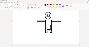
Raster design with Paint
As a first step I used the basic Windows application Paint to create a fast conceptual sketch of my final project. This allowed me to quickly explore proportions, layout and overall shape without worrying about precision.
The process was:
- Open Paint and create a new canvas with a simple resolution (for example 1280×720 px).
- Use the freehand and line tools to draw the main parts of the project (structure, supports, main modules).
- Use colors to differentiate components.
- Save the result as PNG for better quality while editing, and later compress it.
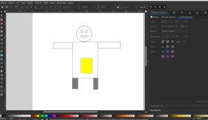
Vector design with Inkscape
After the raster sketch, I moved to Inkscape to create a clean vector version of the design. Vector graphics are scalable and more suitable for technical drawings, laser cutting or CNC preparation.
The steps I followed in Inkscape were:
- Create a new document and adjust the page size to a convenient format (e.g. A4 landscape).
- Import the raster sketch from Paint as a background reference (File → Import) and place it on a locked layer.
- Create a new layer on top and use basic shapes (rectangles, circles, lines) to trace the main geometry of the project.
- Use path operations (union, difference, intersection) to build more complex shapes.
- Add text labels and dimensions to clarify the purpose of each part.
- Save the editable file as .svg and export views as .jpg for the website.
This combination of raster (fast ideation) and vector (clean geometry) helps to move from a rough idea to a more precise design that can be reused later for fabrication processes.
You can download the original design files here:
3D Design
For 3D modelling I experimented with three different programs: Rhino, FreeCAD and Blender. Due to time constraints I focused on basic modelling and did not go deeper into animation or simulation, but I was able to compare different workflows.
3D modelling in Rhino
Rhino is a powerful NURBS-based modeller. I used it to create a first 3D version of the structure of my final project, focusing on curves and surfaces.
Workflow in Rhino:
- Import or recreate the 2D outline from the vector design as curves.
- Use commands like ExtrudeCrv, Loft and FilletEdge to generate the main solid parts.
- Organize the geometry in layers (base, supports, moving parts...).
- Create simple views for documentation and parametric model with grasshopper
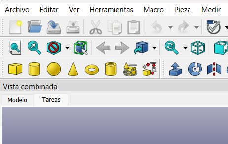
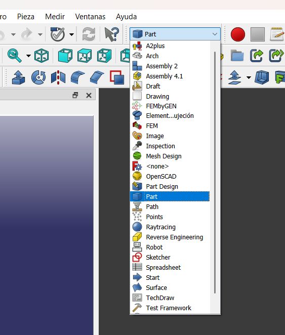
FreeCAD
FreeCAD is an open source parametric modeller. I used it to create a more structured version of the project, where dimensions and constraints can be edited later.
Main steps in FreeCAD:
- Create a new document and switch to the Part Design workbench.
- Make a new Body and start with a Sketch on a main plane (XY).
- Define geometric constraints (coincidence, symmetry, parallel) and dimensional constraints (lengths, angles).
- Use Part design and operations to obtain 3D solids
- Repeat the process for different components of the project.
Once the model was ready, I exported it in two formats:
- FreeCAD native file:
.FCStd(for editing). - STL file:
.stl(for 3D printing or sharing a static version).
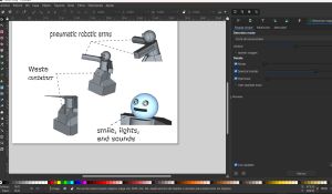
Rendering and visualization in Blender
Blender is mainly used for animation, rendering and more complex scenes. For this week I used it mainly to import the geometry and create better visualizations.
Steps in Blender:
- Import the .stl file exported from 3D scan
- Adjust scale and orientation of the model.
- Add a simple material to the main parts to distinguish components.
Although I did not have enough time to explore animation or simulation, this workflow already gives me a good starting point to later create more advanced visualizations of the final project.
Final Project – First 3D Sketch
Following the weekly requirements, I modelled a first 3D sketch of my possible final project. The model does not yet include every detail, but it captures the main concept, volumes and spatial organization.
The project is A Robot that Hugs in Exchange for Trash and its main function is have a real impact on children .
You can download the original design files here:
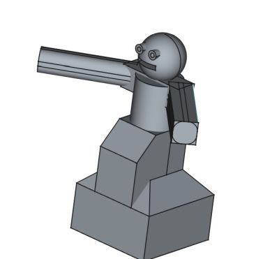
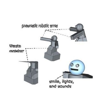
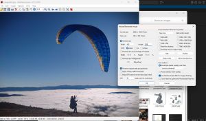
Image Compression – IrfanView 64
To optimize the website and the repository size, I compressed all image files used in this documentation. For that I used IrfanView 64, a free and lightweight image viewer and converter.
IrfanView 64-bit (official site)Steps for image compression in IrfanView 64:
- Open the original image in IrfanView (File → Open).
- Resize the image if needed (Image → Resize/Resample), choosing a smaller resolution suitable for the web.
- Go to File → Save As and select the desired format (e.g. JPG or PNG).
-
Adjust the save options:
- For JPG: set the quality to a value between 70 and 85 to reduce file size.
- Enable “Show preview dialog” to check visually the result before saving.
- Save the compressed file into the
/imagesfolder of the website.
Example of file size reduction:
- Original image: 3.2 MB (PNG, high resolution).
- Compressed image:10,3 KB (JPG, resized).
With this process I ensured that all screenshots and renders load fast on the Fab Academy website while keeping enough visual quality to understand the content.
Video Compression – HandBrake 64
For video compression I used HandBrake 64, an open source and cross-platform video transcoder. I chose it because it is free, easy to use, and provides good control over quality and file size.
Workflow for compressing videos with HandBrake:
- Open HandBrake and select the original video file (Open Source).
-
Choose a preset, for example:
- Fast 480p30 for web documentation.
-
In the Video tab:
- Use the H.264 (x264) codec.
- Set constant quality with a RF value around 20–22 to balance quality and size.
- Check the estimated file size and adjust parameters if necessary.
- Choose the output folder (inside my Fab Academy repo) and click Start Encode.
Example of video size reduction:
- Original video: 21.1MB (1080p, high bitrate).
- Compressed video: 1.44 (480p, RF 30, same duration).
After compression, I uploaded the reduced video to the repository and linked it from this page so it can be viewed or downloaded without exceeding archive limits.
You can watch an example of the compressed video here:
Summary and Reflection
In this second week I evaluated and used different 2D and 3D design tools (Paint, Inkscape, Rhino, FreeCAD and Blender) and created the first digital representations of my possible final project. I also implemented a workflow for compressing images (IrfanView 64) and videos (HandBrake 64) so that all documentation is efficient for web publication.
I have basic experience using 2D and 3D design software, so preparing this assignment was straightforward for me.
There is plenty of information and many tutorials available for each tool, which helps in developing the required skills and functionalities.