Development
Weekly progress log and design iterations
what this page is.
This is the build journal of 3m, written after the defense rather than before it. The Final Project page holds the clean result — the one-minute video, the slides, the closing summary. This page holds the road there: the decisions, the dead ends, the two pivots that reshaped the project, and what each Fab Academy week actually fed into it. It is honest on purpose. The failures are not edited out; they are where most of the learning sits.
the pivot: from a four-leg desk to one module.
The project I defended is not the project I proposed. I started with a four-leg, electronically height-adjustable standing desk: four telescopic legs, four motors, a master coordinating them over a UART bus. What I defended is a single telescopic module that raises and lowers a load under its own controller. The desk is now one possible configuration of that module, not the deliverable.
The project shrank in two steps, and I am not going to dress them up.
The first step was on May 7. I dropped the steel-and-TR10×3 final design for the build phase. Committing to an external metal fabricator inside a 33-day window, with no prior relationship, was a procurement risk I could not absorb. So the prototype moved to materials I could cut, print and source next-day: a T8×8 lead screw from the 3D-printer parts ecosystem, and a telescopic body I could make in the lab instead of ordering welded.
The second step is the real one: four legs became one. The reasons, in order of honesty — the calendar; a long tail of small unforeseen complexities (every printed part needed two or three iterations, every tolerance needed a test print, and the anti-rotation problem only showed up once the screw was actually turning); and, plainly, my own time management. Faced with delivering four half-working legs or one module that works end to end, I chose the module.
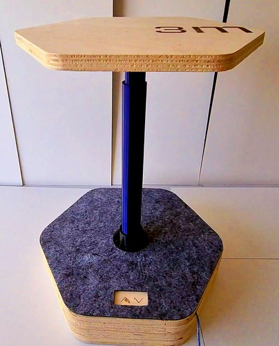
Naming it made the idea settle. 3m — minimalist mono-module. One module is the unit. Four under a tabletop are a desk; two with a beam are a shelf; one on its own is a sit-stand pedestal — which is exactly what 3m is: a ~40 cm base resting on a normal ~74 cm table, a 28 cm stroke, reaching about 178 cm of standing working height and carrying up to roughly 3 kg.
There was a second, smaller pivot hiding inside the build — from PVC tubes to fully printed bodies — but that one is mechanical and earns its own section below.
driving the motor: the test stand.
This section starts with a conversation, not a component. I was overwhelmed — convinced the full four-leg desk would never be finished in time — and Pablo reframed the whole thing in one sentence: my project was, in the end, a tabletop sitting on four modules, and each module was just a leg. That reframing is what let the project breathe. If the desk is four modules, then one working module is already the project; the other three are scale, not substance.
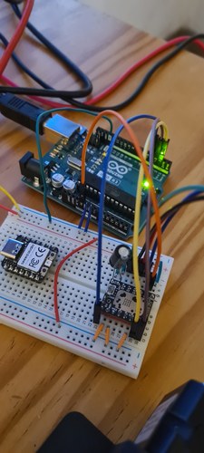
Pablo’s second piece of advice was about method: rapid prototyping. My leg-controller PCB was not designed yet, and he told me not to wait for it. Grab whatever I had — any Arduino board, a breadboard — and build a quick-and-dirty version to validate the idea first. That is exactly how the real proof of concept got built: from the parts already on my desk.
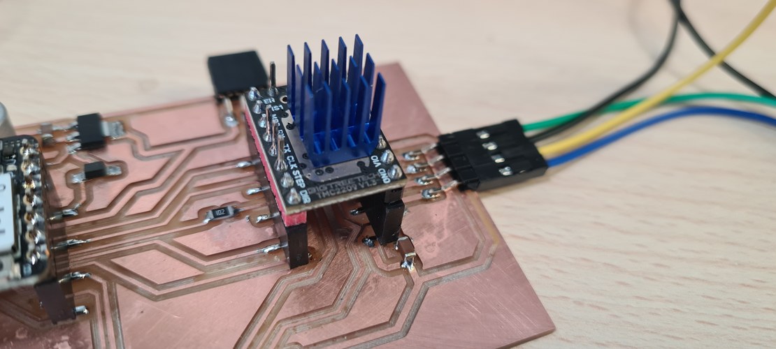
the driver.
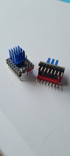
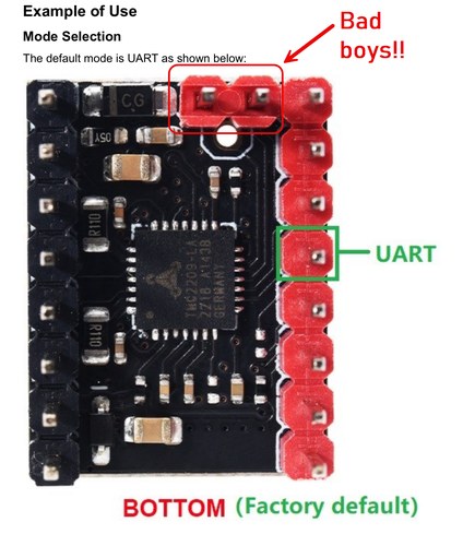
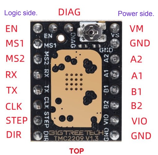
The heart of the stand is the TMC2209 SilentStepStick (BigTreeTech v1.3) — the silent, microstepping stepper driver the whole project runs on. For the bring-up I used it in standalone step/dir mode: no UART, MS1/MS2 low for 1/8 microstepping, CLK to GND.
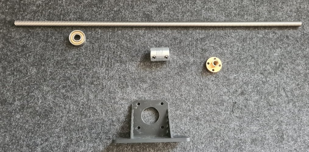
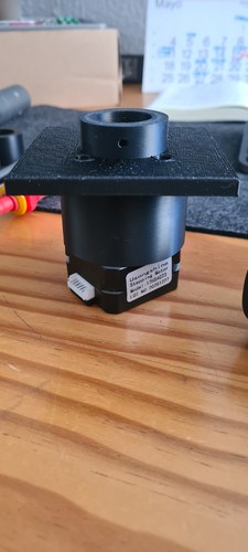
the stand, in parts.
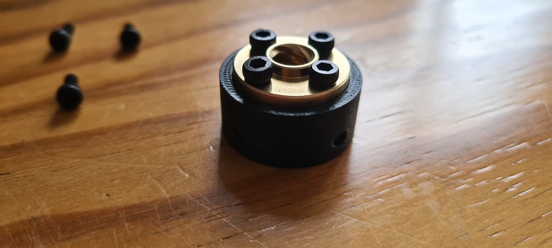
The drive train is simple: a T8×8 lead screw, a 608ZZ bearing, a flexible 5×8 coupling, a brass T8 flanged nut, and a printed motor mount.
the headaches.
The breadboard is where rapid prototyping earned its scars.
On the BigTreeTech v1.3 module, the DIAG and VREF pins of the top auxiliary header land in the same breadboard rows as the logic and power pins. A jumper meant for the enable line was also sitting on VREF, and VREF was shorting against VM through the trimmer body. The result: VREF collapsed to a few millivolts, the driver looked dead, and before I understood what was happening I cooked two modules in a row. The fix is brutally simple — cut the DIAG and VREF pins flush with a pair of pliers before seating the module. Two dead drivers is what that lesson cost.
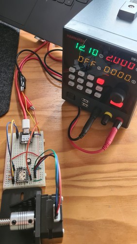
Two smaller things bit less hard but are worth writing down. The PSU current limit has to be generous: with it set low, the chopper’s instantaneous peaks trip the supply into constant-current and the motor will not even start, even though the average draw is tiny. I run the HANMATEK at a 2 A limit. And I set VREF conservatively, creeping it up in small steps while watching the driver temperature, rather than going straight for the nominal current.
proving it moves.
With the short fixed, the rest came together fast. First on an Arduino UNO R3, exactly as Pablo had pushed — validate on whatever is at hand before the custom board exists.
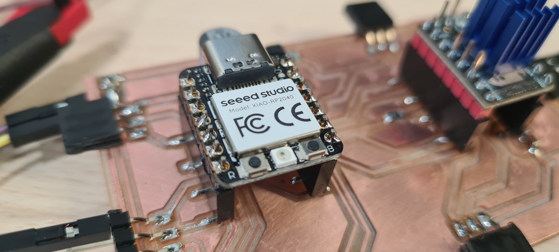
Then the same ramp on the XIAO RP2040 — the MCU that actually lives in the leg.
Two clean ramps later — UNO first, then the XIAO — the drive was validated at around 240 rpm, roughly 32 mm/s on the T8×8, with no lost steps. The Usongshine 17HS4023 had done its job as the bring-up motor; the next step was to swap it for the LDO-42STH48 and re-tune the current.
first mechanical coupling: the torque wall.
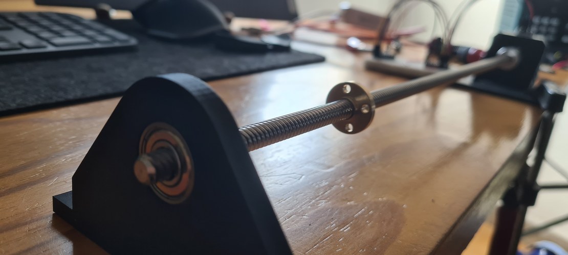
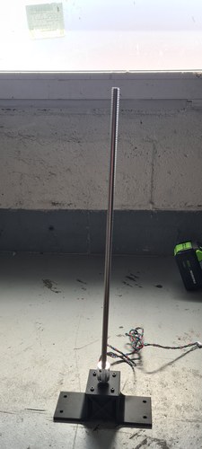
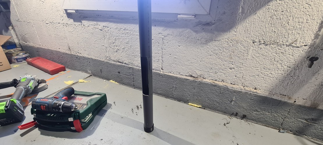
On the stand the drive turned with nothing to lift. The first time the lead screw was set up full-length and asked to carry a load, two limits appeared at once — one mechanical, one in the motor.
The mechanical one was the screw. The T8×8 is 400 mm long, and held only at the motor end it behaved like exactly what it is: a long thin rod spinning off-center. As soon as it picked up speed it whipped like a skipping rope, and that runout is not just ugly — it loads the motor’s own bearing and will chew it up. The fix is geometric, not electronic: support the free end. A 608ZZ at the far end turns the cantilever into a shaft guided at both ends and the whip is gone. That is why this build has a bearing bracket at all.
The second limit was the motor, and it is the wall this section is named for. The Usongshine 17HS4023 that had driven everything so far was never meant to lift anything — it is a ~14 N·cm stepper at 0.7 A, picked because it was cheap and already on my desk, good enough to prove the firmware, the wiring and the ramp. Asked to push the screw at low speed against the resistance of the assembly, it had nothing left. It sat there while I told it to move. That was always going to happen; the loaded coupling is just where it stopped being a number in a datasheet and became a motor standing still.
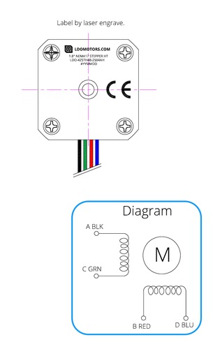
So the decision made itself. A leg that lifts needs real torque, and the motor I had earmarked since the very first BOM was the LDO-42STH48-2504AH — Class H, roughly four to five times the Usongshine’s torque, and a clean drop-in: same 42×42 body, same 5 mm shaft, same coupling. Swapping it in only meant re-tuning the TMC2209 current — the LDO wants a much higher VREF — and nothing else mechanical changed. The LDO is the motor in the final module.
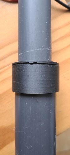
from PVC tubes to printed bodies.
The first leg was built around PVC. Two nested evacuation pipes — DN32 inside DN40 — with printed parts pressed into them to do the real work: a block to hold the brass nut, a bracket to hold the bearing, a plate to carry the motor. The PVC gave me a cheap, straight, off-the-shelf tube; the printed parts gave it function.
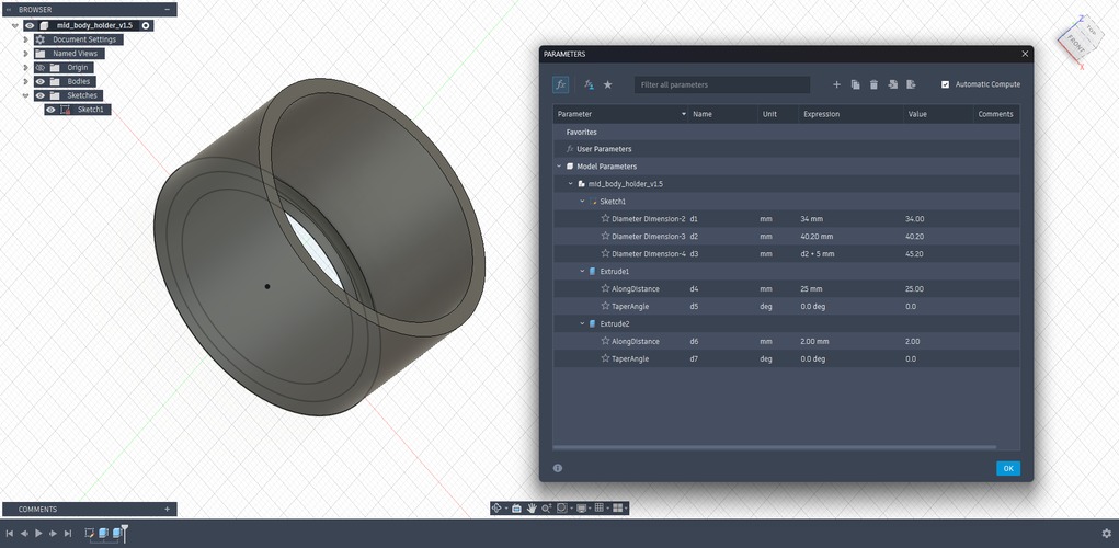
designing the parts.
Every one of those inserts was modelled parametrically in Fusion 360, so a single dimension change ripples through the part instead of forcing a redraw.
I’ll be honest about this part: CAD does not come naturally to me, and none of it was quick. I redrew parts more times than I’d like to admit. But somewhere in the last stretch of Fab Academy it clicked, and I came out feeling like I’d unlocked the next level in a skill I actually want to keep going with — Fusion is something I want to push much further, not just the modelling but CAM and animation too.
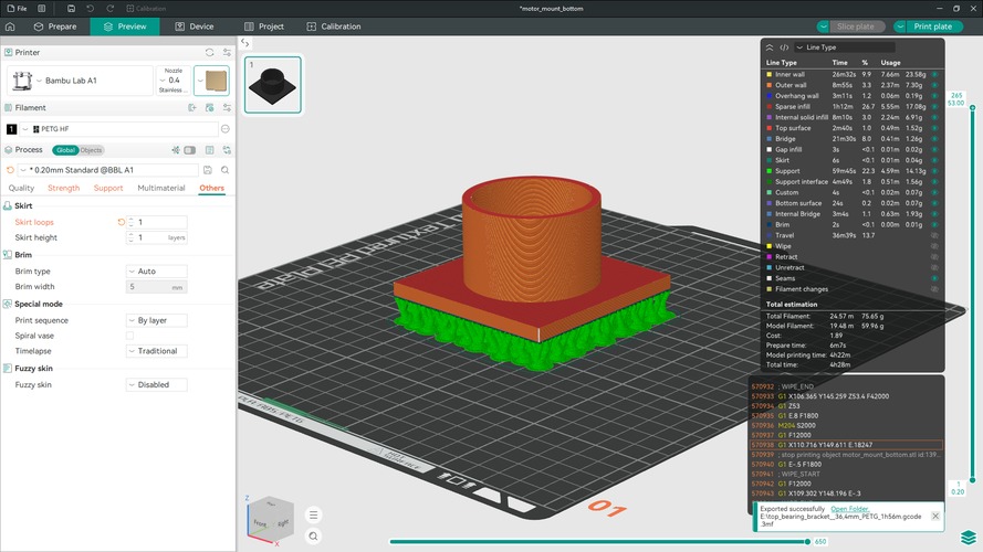
printing them.
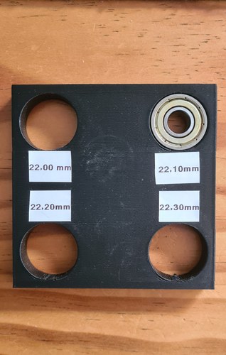
Everything that carries load or holds a tolerance is PETG, not PLA — PETG keeps its shape against the heat coming off the driver and the motor, and resists creep under a standing load. On the Bambu A1, PETG prints about 0.2 mm under the modelled size on outside diameters, so that offset is built into the parts; and where a fit really matters I print a short tolerance ladder and measure rather than trust the number. The 608ZZ seat, for one, came out best at 22.10 mm across a four-step test.
With the inserts modelled, printed and dialled in, the mechanism had its moving parts. What it still didn’t have was its own electronics: until now the motor had been driven from a breadboard.
the electronic design.
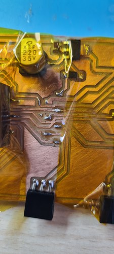
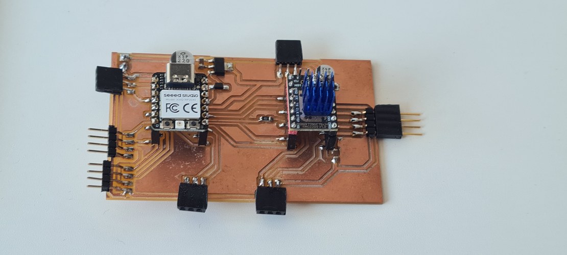
With the drive proven on the stand, the motor was still being run from a breadboard. The next step was to give the leg a board of its own: a single milled PCB carrying the XIAO RP2040 and the TMC2209, every connector it needed, and its own power stage.
designing the PCB.
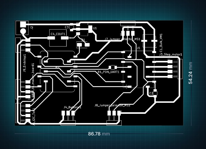
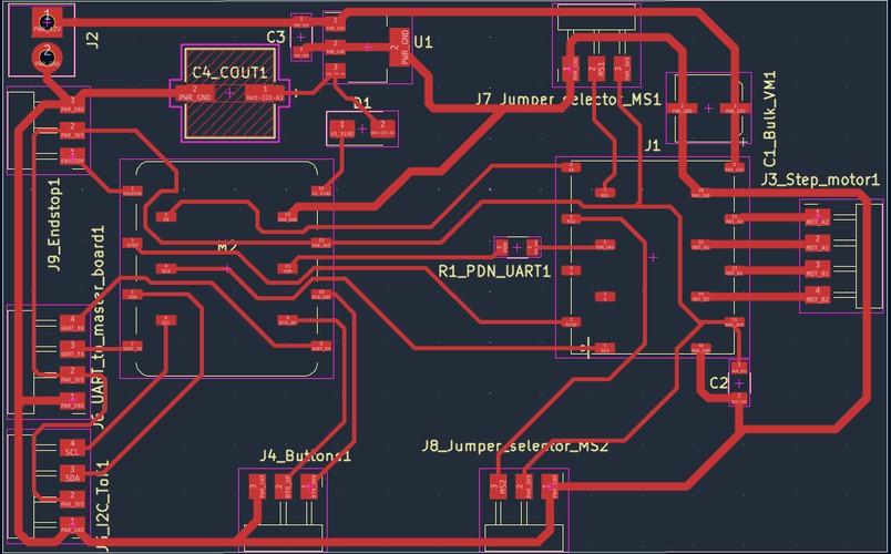
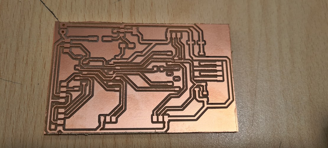
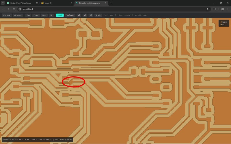
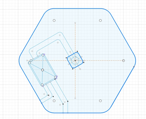
I designed the board in KiCad and milled it single-sided on the Roland MDX-20, which sets the hard constraint for the whole layout: one copper layer, so no trace can cross another. Fitting the XIAO, the driver, the motor and signal connectors, the microstepping jumpers and the power components onto one face without a single crossing was by far the hardest part — most of the time went into moving parts around and re-routing, because KiCad won’t push existing tracks out of the way when you nudge a footprint.
Two changes from Adrián unblocked it. The first was the driver footprint. The off-the-shelf TMC2209 socket left no room to route between its pins, and a mods simulation showed the copper shorting under it. So instead I built a custom staggered SMD footprint for the driver, copying the geometry of the XIAO socket I already knew worked — a zigzag of pads about 3.3 mm peak-to-peak — and saved it as a .kicad_mod in the project library. Staggering the pads opens a gap between them wide enough for the 1/64″ mill to leave clean copper, so traces can slip through to their pads instead of crossing.
The second was power. Rather than feed the XIAO from USB, the board takes a single 12 V supply for the motor and derives its own logic rail from it with an LM2940 linear regulator (5 V, SOT-223), with a 1 µF input cap and a 220 µF output cap. A 1N5819 Schottky on the XIAO’s 5 V pin means I can plug USB in to reprogram the board while it is powered without the two supplies fighting each other. Signal traces are 0.4 mm, power and motor traces 0.8 mm; the layout passed DRC.
milling and soldering.
With the board milled, I used the interactive BOM (the iBOM plugin) as a printed assembly checklist — every component with its value and footprint, ticked off as it went down.
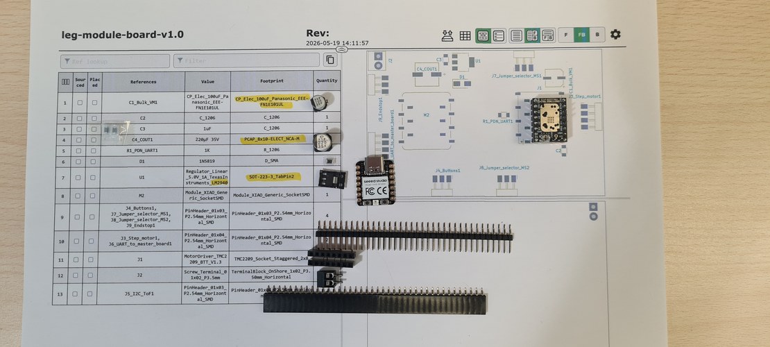
SMD soldering followed the method Adrián walked us through in the electronics production week, and it went smoothly. The XIAO and the TMC2209 sit in sockets, so either can be swapped or reused.
bring-up and the hunt for a short.
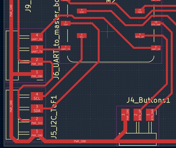
Before powering anything up, the motor had to be wired right. The LDO-42STH48-2504AH is a bipolar stepper, so its four leads form two coils, and each coil has to land on the right driver pins — cross a pair and the motor only judders in place. I found the pairs with a multimeter: black–green read 1.6 Ω and red–blue 1.7 Ω, so those are the two windings (A–C and B–D in LDO’s diagram). With the coils mapped, the TMC2209 current is set through its Vref, following Vref = I_RMS × 1.414 on the v1.3 board.
First checks looked clean: no obvious shorts, grounds connected. But the moment I powered everything up, the motor only buzzed and oscillated instead of turning. Probing the TMC2209’s STEP and DIR pins, instead of clean logic levels I saw an indefinite ~1.2 V flickering — the sign that the XIAO wasn’t managing to drive those lines at all.
A continuity check found it: a short between D2 and D3 of the XIAO socket, carried straight through to STEP and DIR. The cause wasn’t a solder blob but the layout — two traces sat so close that the 1/64″ mill couldn’t cut a gap between them, so they came out joined. It is the classic MDX-20 gotcha: when the clearance drops below the cutter diameter (~0.4 mm), the mill simply can’t separate the traces. In hindsight it was already there in the mods toolpath simulation; I had looked straight past it.
The short sat right under the XIAO socket, so I could not just scrape it. Nuria gave me amber Kapton tape to shield the neighbouring parts from the heat gun while I lifted the socket off, and then I separated the two traces by hand with a precision knife.
That fixed the signals, but the motor still would not run — and this time it was the same lesson the breadboard had already taught me. The Fab Lab’s power supply could not reach the 2 A the driver needs; below that, the chopper’s current peaks trip the supply’s protection and the motor never starts. The next day I brought my own PSU, raised the current limit, and the motor finally turned.
the provisional assembly.
With the motor verified on the board, the next move was to start joining things — the drive, a base, and a pair of tubes — into something I could stand up and run.
a base worth standing on.
The drive needed something solid to bolt to. I cut a base out of plywood with a jigsaw, to turn a bare mounting plate into something a bit more presentable.
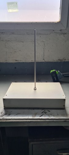
a working stack, and two decisions.
With everything bolted together I ran the whole thing in the workshop, driving the bodies up and down.
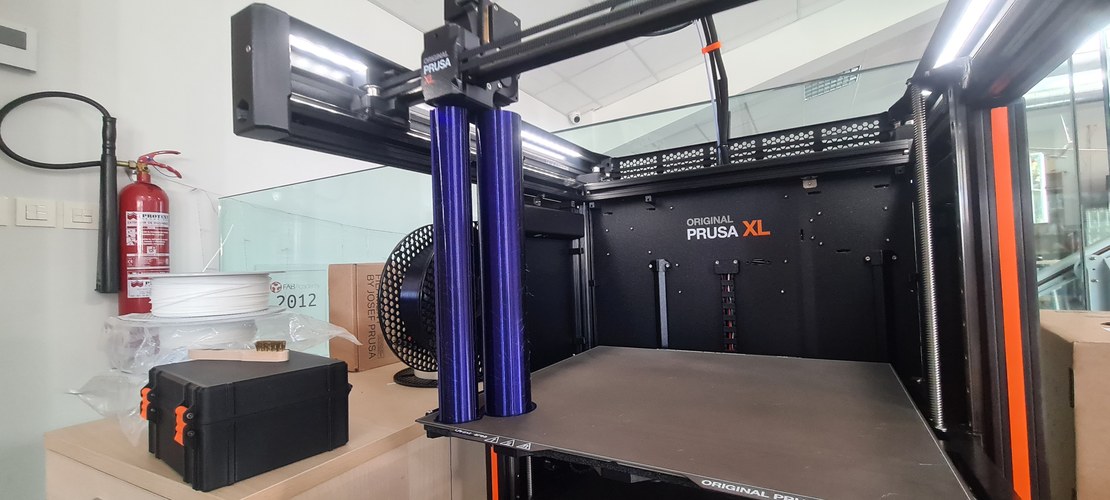
Seeing it work as an object on a desk settled two things. First, the controls: since the module always sits on top of the table, the buttons belong on the base, where a hand naturally reaches them. Second, the height: the bodies were taller than they needed to be, and trimming them is trivial, so I cut them down to 360 mm each — which is also the tallest a body can be printed in one piece on the Prusa XL, whose build volume is 360 × 360 × 360 mm.
rotation or translation?
There is one thing the provisional rig does that looks like a problem and isn’t, quite. With nothing holding it, the upper body turns with the screw instead of climbing — rotation in, rotation out. I never worried about it, because in my head this was always a table: with a shared top tying three legs together — or even two, on a two-leg table — no single leg can rotate, so the only motion left is linear. The constraint comes from the assembly, not from the leg on its own.
But 3m ended up as a single, self-contained module, with no tabletop to lean on. So it has to carry its own anti-rotation.
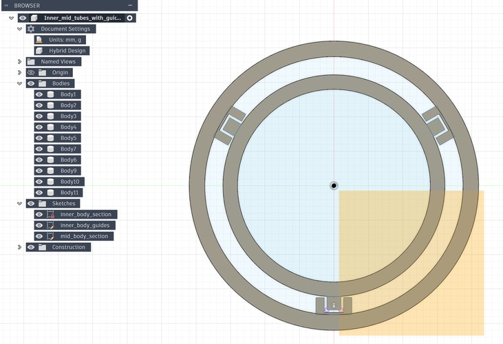
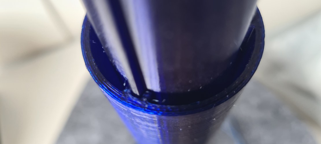
the printed bodies and their guides.
Before committing to a long print, I modelled several internal-guide concepts in Fusion and printed a few of them, keeping the one that held up best. The idea that survived is a set of three guide ribs spaced at 120° on the inner body, each running in a matching groove in the mid body — one geometry that does the sliding guide and the anti-rotation at once.
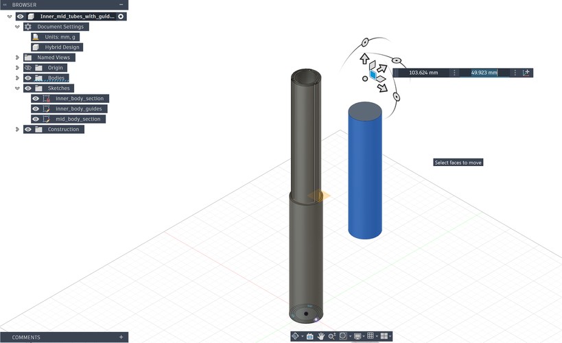
The bodies are printed whole, in PETG, on Adrián’s Prusa XL — which is exactly why the 360 mm height matters: it is the full Z the machine can manage in a single piece.
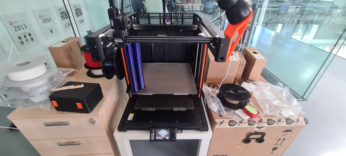
The design started as three concentric bodies. The third was dropped: the extra stage added more complexity than the Final Project deadline could absorb, so 3m settled on the two-body stack — inner and mid — that you see here.
system integration.
The stack worked. What was left was the final touch: turning a working mechanism into a finished object, and pulling the lab’s fabrication processes into one piece — CNC, laser, and the printer.
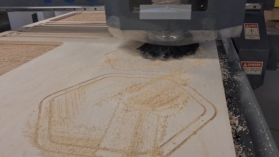
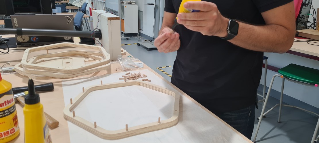
a base off the CNC.
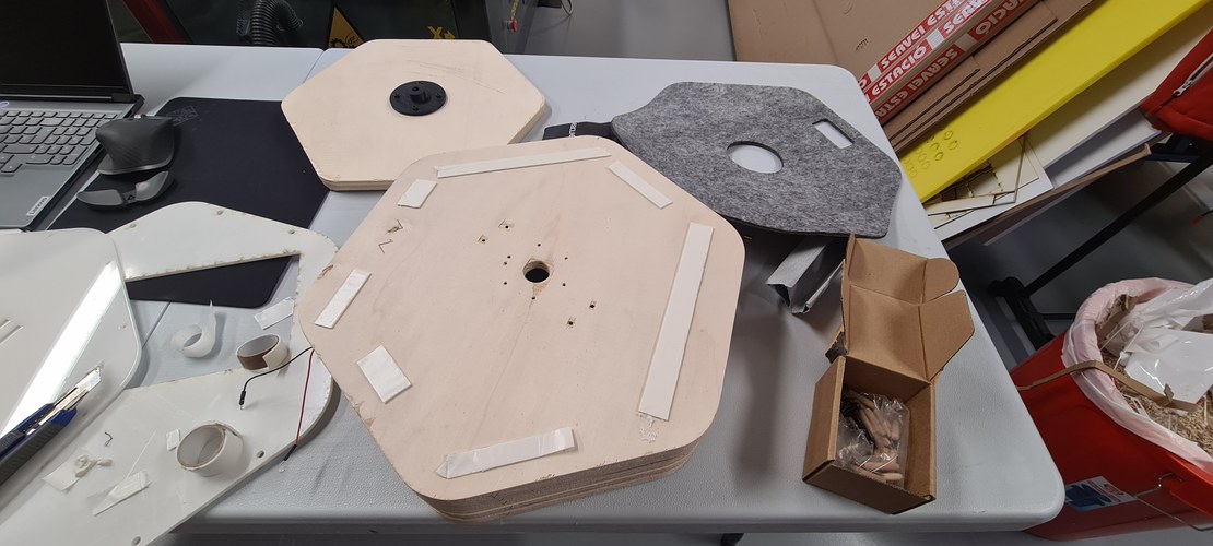
For the base I reached for another process, the CNC router. The shape is a hexagon with rounded corners, cut as a set of rings that stack up to the height I needed.
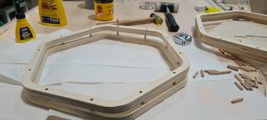
The rounded-hexagon profiles, routed straight into the plywood:
The rings are joined to each other with wooden dowels, a little carpenter’s glue, and clamping pressure — no screws through the stack.
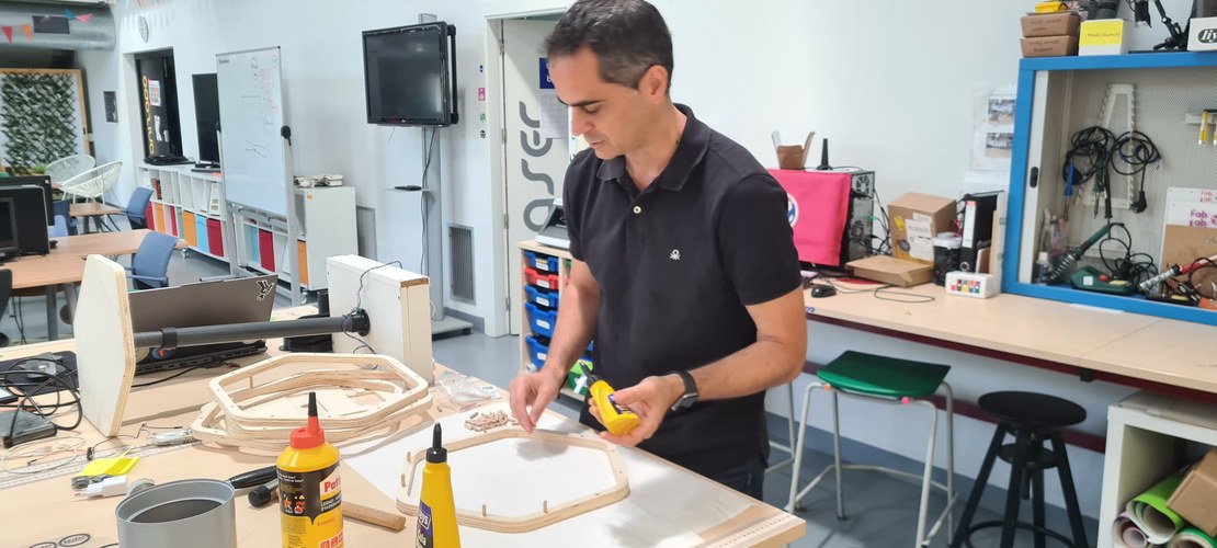
Then the whole base went back to the workshop to be sanded smooth.
housing the electronics.
The underside of the base is where everything lives — the PCB, the motor, the touch sensors. Instead of bolting boxes on, I pocketed the base on the CNC so each part drops into its own recess, with channels routed for the cables. I laid all of that out in Fusion first: the footprints to clear, and the path every wire had to take.
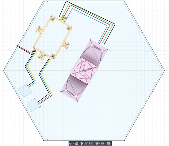
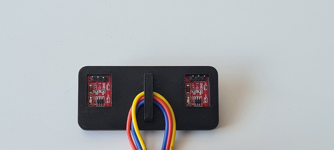
The two boards that go in are the milled control PCB (XIAO RP2040 + TMC2209) and the touch panel carrying the two TTP223 capacitive sensors.
Test-fitting the parts into their pockets:
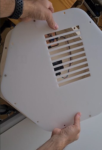
The bottom is closed with a cover laser-cut from white acrylic, with a slotted “cooling bay” over the electronics. It holds to the base with neodymium magnets — no fasteners, and it lifts off whenever I need to get back in.
the controls, and the top.
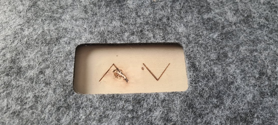
The top face of the base is finished with grey felt, also laser-cut. A window is cut into it for the touch sensors, and beside it I engraved two minimalist arrows — up and down — so the controls read at a glance. The felt is held on with double-sided tape.
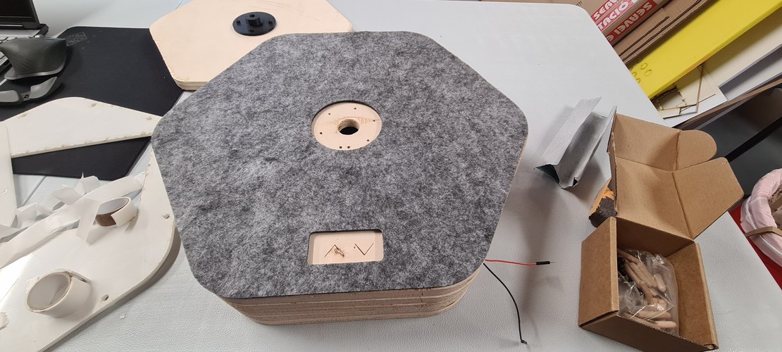
The sensors were checked on their own first, then again once they were seated in the base.
The part that actually moves is the top platform — a wood hexagon that rides on the bodies and carries whatever you set on it up and down. I engraved the logo into it, since it is the surface you end up looking at.
chasing the press-fit.
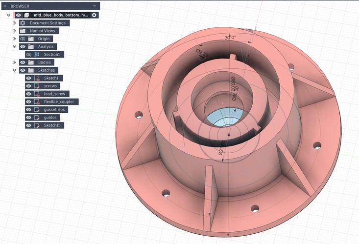
One Fusion part pulled most of this together: the bottom housing for the mid body (mid_blue_body_bottom_housing). It had to do three things at once. Underneath, it has to clear the coupler where it protrudes and leave room for the lead screw to pass through. On top, it carries grooves cut to a precise tolerance, so the mid tube presses straight into it. And around the outside it grows a skirt of holes, where four to six screws tie it down to the wood base.
Press-fit became the thread running through the whole project — a slightly stubborn goal of holding the critical joints together with geometry alone, and keeping screws, glue, and epoxy out of them wherever I could.
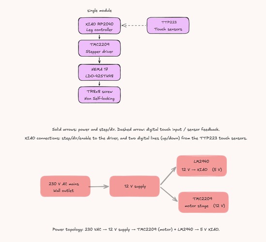
the module, in one diagram.
The system diagram I drew during System Integration week, updated to the single module 3m actually became: the control chain on top — XIAO to driver to motor to screw, with the touch sensors feeding back — and the power topology below.
the firmware.
The control logic is deliberately small. The XIAO RP2040 runs FastAccelStepper, which generates the step pulses on the RP2040’s PIO rather than in software, so the timing stays clean while the loop does everything else. A single constant, STEPS_PER_MM, ties the motor and screw to the real world: it turns a target in millimetres into a step count from the 200-step motor and the 8 mm lead of the T8×8 screw.
The interface is the two TTP223 boards, each a plain digital line: hold UP and the leg climbs, hold DOWN and it descends, release and it stops. Two soft limits — a minimum and a maximum height in millimetres — are checked against the tracked position so the nut is never driven into either end of the screw. There is no homing switch; the firmware trusts its own step count from a known start, which is enough for a leg that moves slowly under a light load.
measuring what you can’t trust.
The recurring lesson of the build was that the printed-on number is rarely the real one, and the only fix is to measure. PVC “DN” sizes are nominal, not the true outside diameter — DN32 is 32.25 mm, DN40 is 40.35 mm — so every tube went under the calipers before anything was designed around it. Print tolerances were found the same way: a short ladder of test fits (the 22.10 mm step among them) and a 0.2 mm compensation built into the parts, rather than trusting the slicer to hit the model dimension.
The same habit ran through the electronics. The motor’s coil pairs were not guessed from the wire colours but read with a multimeter — black–green 1.6 Ω, red–blue 1.7 Ω — before anything was powered. And the TMC2209 current was set from a measured Vref (Vref = I_RMS × 1.414), crept up in small steps while watching the driver temperature, not dialled straight to the nominal figure.
what each Fab Academy week contributed.
3m is mostly an assembly of what the weekly assignments taught, brought together in one object:
- Week 04 — embedded programming: the XIAO RP2040 and capacitive touch, which became the controller and the up/down inputs.
- Week 06 — electronics design: the KiCad workflow and the first XIAO board, the basis for the leg-controller PCB.
- Week 07 — computer-controlled machining: the CNC and CAM that later cut the plywood base.
- Week 08 — electronics production: MDX-20 milling and SMD soldering, exactly what produced the control board.
- Week 09 — input devices: reading a sensor on the XIAO, the same pattern as the touch inputs.
- Week 10 — output devices: driving a motor from a custom board, the core of the machine.
- Week 11 — networking: the addressing bus, the seed of the multi-leg architecture.
- Week 15 — system integration: where the system diagram and the four-leg concept were drawn.
- Week 17 — applications and implications: where the project was reframed as a modular telescopic system.
- Week 18 — IP and income: the licence stack for the docs, firmware and hardware.
made vs. bought.
Made — designed and fabricated in the lab:
- the milled leg-controller PCB (MDX-20);
- the printed parts: the two telescopic bodies, the motor mount, the nut block, the mid-body bottom housing, the touch panel;
- the CNC plywood base;
- the laser-cut acrylic cover and the felt top, engraving included;
- the firmware.
Bought — off the shelf:
- XIAO RP2040, TMC2209 driver, LM2940 regulator, passives and the 1N5819;
- the LDO-42STH48-2504AH motor, the T8×8 screw and brass nut, the flexible coupler and the KFL10 bearing;
- the two TTP223 touch boards;
- neodymium magnets, dowels and screws;
- raw stock: PETG and PLA filament, plywood, acrylic, felt.
Quantities, sources and costs for every part are in the bill of materials.
the build timeline.
3m was built in the 33 days between the build-phase decision on 7 May and the defence on 8 June. The Gantt below is that month as it actually ran, not as I first planned it — hover any bar for its dates. The red bars are the critical path the whole build hung on; the green diamonds are the three states I could point at and call proven: the control board fabricated, the module working end to end, and the defence itself. Read left to right, it is the same story this page tells in prose, compressed into one chart.
what works, what doesn’t, and the next spirals.
Works: with the LDO motor the leg drives the screw under load; the two-body stack rises and falls on its printed guides without rotating; the touch controls and their soft limits behave; and the electronics sit inside the base under a magnetic cover instead of hanging off it.
Doesn’t, yet: the screw is non-self-locking, so the leg back-drives under load when the motor is unpowered — it needs holding current or a brake to stay put on its own. It is one module, not the four-leg desk. It runs from an external 12 V supply, with no integrated power yet. And the third concentric body was cut for the deadline, so the travel is shorter than the design allows.
Next spirals: the integrated 24 V supply with the DC-DC stage from the four-leg diagram; the master-plus-bus architecture to tie several legs together; the third body back for full travel; a self-locking screw or a brake; and more time in Fusion, on CAM and animation as much as modelling.
the finished module.
Stripped to a single module, 3m does at one corner what the four-leg desk was meant to do across all of them: press up and it rises, press down and it drops, release and it stops. It is a small machine, but a complete one — designed, milled, printed, cut and coded in the lab — and it stands as the unit the rest of the desk would simply repeat.
bill of materials.
The full parts list — quantities, sources and approximate costs — is kept on its own page: the bill of materials. It covers one finished module; the bring-up motor and the stand bearing are not counted.
licence.
3m is fully open, attribution only. The work is split across three licences, each matched to the part it covers:
- Documentation and design — this page, the Fusion files and drawings — CC BY 4.0.
- Firmware — the XIAO RP2040 source — MIT.
- Hardware — the physical module — CERN-OHL-P 2.0, the permissive variant.
3m: minimalist-mono-module © 2026 Íñigo Gutiérrez Febles, licensed under CC BY 4.0.
The reasoning behind this stack, and the dissemination plan, are in the IP and income week.
design files.
Everything needed to rebuild 3m is here, grouped by what it is. The split by licence is in the licence section above: the firmware is MIT, the board is CERN-OHL-P 2.0, the CAD and drawings are CC BY 4.0. Printed parts come as both the Fusion source (.f3d) and a ready-to-slice .stl; cut parts come as .dxf.
firmware.
- leg controller, final — FastAccelStepper on the RP2040 PIO, two TTP223 touch inputs for up and down, soft travel limits: leg_module_FastAccelStepper.ino
- motor bring-up — the first sketch that turned the motor, AccelStepper with a trapezoidal ramp: Accel_stepper.ino
electronics.
- KiCad project, v1.0 — schematic, board and project library for the leg-module PCB: KiCad-leg-module-board-v1.0.zip
- staggered driver footprint — the custom TMC2209 socket that opened a gap wide enough for the 1/64″ mill: TMC2209_Socket_Staggered_2x8.kicad_mod
- board and schematic renders — PNG exports of the design: KiCad-pngs-leg-module-board.zip
printed parts.
Fusion source plus STL, all printed in PETG.
- concentric bodies with guides — the inner and mid tubes carrying the 120° anti-rotation ribs, printed on the Prusa XL. Each body as its own STL: inner STL · mid STL · Fusion · DXF
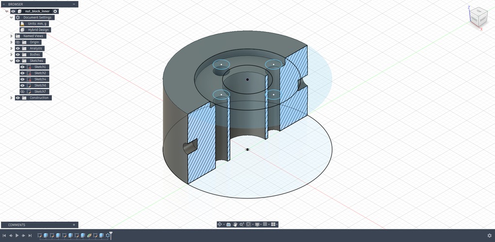
- nut block, inner — houses the T8 brass nut: STL · Fusion · DXF
- inner body top holder — closes the top of the inner body: STL · Fusion · DXF
- mid body bottom holder — STL · Fusion · DXF
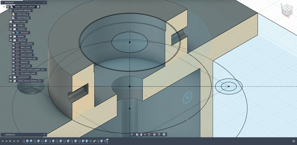
- motor mount — holds the NEMA 17 at the base of the module: STL · Fusion · DXF
- touch sensors holder — seats the two TTP223 boards: STL · Fusion · DXF
- electronics case — the housing that sits in the CNC base: STL · Fusion · DXF
- cable clip — keeps the wiring tidy inside the base: STL · Fusion · DXF