WEEK 10 OUTPUT DEVICES
INTRODUCTION
We can consider this week's assignment as a continuation of the previous one, since in Input Devices we talked about devices that provide information/signals to our controller, while this week we are going to focus on devices that receive signals/information from the controller.
Therefore, following this reasoning, both for the Group Assignment and the Individual Assignment, we will start from the PCB and temperature sensor that we used during the previous week.
SCHEDULE
As in other weeks, the work plan is as follows:
- Thursday: During lunch, I planned to watch Neil's class recording. That was the idea, but due to work-related reasons it was impossible, so I watched it on Friday during lunch instead. In the afternoon, I attended the class explanation with my tutors, who had to explain everything from the beginning since I had not been able to watch the lecture beforehand.
- Friday: I watched the class during lunch, without being able to do anything else throughout the day.
- Saturday: I dedicated the day to thinking about and developing the assignment, deciding which devices to use and how to connect them, as well as explaining and refining the Arduino code with ChatGPT that I was going to use.
- Sunday: I dedicated the day to building the website using the material prepared the previous day, as well as correcting errors.
- Monday: After work, I presented the assignment together with my classmates to my tutors.
- Tuesday and Wednesday: I reviewed and corrected previous weeks' assignments during the time I had available after work.
As in other weeks, the work is divided into two parts
This time I am going to start with the individual part, since I am using the board from the previous week. I will first explain what I have added, and then perform measurements on the final result.
INDIVIDUAL ASSIGNMENT
Focusing the assignment toward the Final Project, I decided to incorporate an OLED display into the PCB, where the temperature measured by the connected sensor will be displayed.
OLED 0.96 INCH DISPLAY
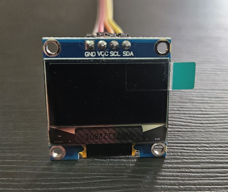
The connection is made using four pins:
- VCC -> 3.3V
- GND -> GND
- SCL -> SCL (D5)
- SDA -> SDA (D4)
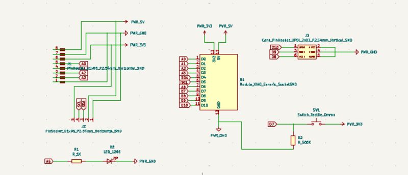
The connection is straightforward because when I designed the PCB, I already planned for the I2C communication used by this display, leaving the corresponding pins available for connection. Nevertheless, I reviewed the previous documentation to make sure the wiring was correct.
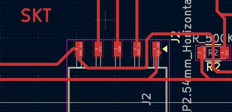
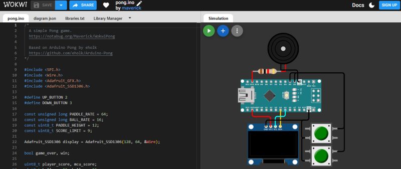
To ensure the connection was correct, I also reviewed the OLED wiring in WOKWI, a platform I had used in the Electronic Design assignment, confirming that no intermediate resistor or any other additional component was needed.
PROGRAMMING
Since I had already used this OLED display during Week 4, Embedded Programming, the Adafruit SSD1306 library was already installed in my Arduino application, as it is required for the display to function.
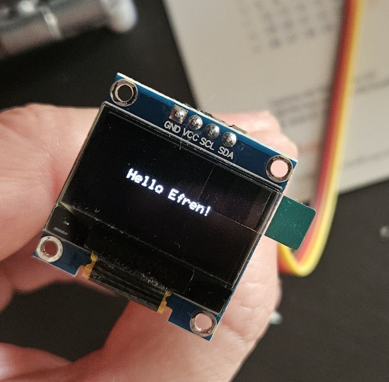
Once connected, the first step was simply to verify that the display was working. Therefore, the best way to do that was to upload a simple "Hello Efren" test code.
Hello Efren code
          #include
#include
#include

#define SCREEN_WIDTH 128 // OLED display width, in pixels
#define SCREEN_HEIGHT 64 // OLED display height, in pixels

#define SCREEN_ADDRESS 0x3C // 0x3D or 0x3C depending on brand

Adafruit_SSD1306 display(SCREEN_WIDTH, SCREEN_HEIGHT, &Wire, -1, 1700000UL, 1700000UL);


void setup() {
  // initialize Serial port
  Serial.begin(115200);

  // give the screen some time to power up
  delay(50);

  // initialize display
  display.begin(SSD1306_SWITCHCAPVCC, SCREEN_ADDRESS);
  display.clearDisplay();
  display.display();

  // text settings
  display.setTextSize(1);
  display.setTextColor(SSD1306_WHITE);
}


void loop() {
  // clear the buffer
  display.clearDisplay();
  // pick a position
  display.setCursor(28, 25);
  // write to buffer
  display.print("Hello Efren!");
  // send buffer
  display.display();
}
After confirming that the OLED display was working correctly, the next step was to verify that both, the input (temperature probe) and the output (OLED display) could operate simultaneously.
As in previous assignments, the Arduino code was generated with the assistance of ChatGPT after describing the hardware setup and presenting the connections in the corresponding schematic diagram.
temperature code
          #include
#include
#include
#include
#include

#define SCREEN_WIDTH 128
#define SCREEN_HEIGHT 64

// OLED
Adafruit_SSD1306 display(SCREEN_WIDTH, SCREEN_HEIGHT, &Wire, -1);

// Pin del sensor 1-Wire
#define ONE_WIRE_BUS D0

OneWire oneWire(ONE_WIRE_BUS);
DallasTemperature sensors(&oneWire);

void setup() {

  Serial.begin(115200);

  // Inicializar OLED
  if (!display.begin(SSD1306_SWITCHCAPVCC, 0x3C)) {
    Serial.println("OLED not found");
    while (true);
  }

  // Inicializar sensor
  sensors.begin();

  display.clearDisplay();
  display.setTextSize(2);
  display.setTextColor(SSD1306_WHITE);
}

void loop() {

  sensors.requestTemperatures();

  float temperature = sensors.getTempCByIndex(0);

  Serial.print("Temperatura: ");
  Serial.println(temperature);

  display.clearDisplay();

  display.setCursor(0, 10);
  display.print("Temp:");

  display.setCursor(0, 35);
  display.print(temperature);
  display.print(" C");

  display.display();

  delay(1000);
}
After confirming that the display and the temperature probe was working correctly, I started developing code focused on the final project. At this point, I do not yet have the actuator that I will eventually use, but the PCB already includes a LED and a BUTTON, which are sufficient elements to simulate the system behavior. Therefore, the first code implemented the logic required so that when the button is pressed, the LED turns on—simulating the actuator—and remains on until the temperature exceeds 30°C.
From this point on, I progressively improved the code by introducing a delay before turning the LED off, during which the LED must blink.
The initial prompt I started from was the following:
"In this variant, since the PCB includes both a push button and an LED, the system behavior was modified as follows: if the temperature is below 30 °C and the button is pressed, the LED turns on and remains on while the temperature stays below 30 °C. When the temperature rises above 30 °C, the LED starts blinking for 5 seconds and then turns off. The LED will not turn on again until the button is pressed once more and the temperature drops below 30 °C. If the temperature is above 30 °C, pressing the button has no effect."
Temperature Oled Led and Button code
          #include
#include
#include
#include
#include

#define SCREEN_WIDTH 128
#define SCREEN_HEIGHT 64

// OLED
Adafruit_SSD1306 display(SCREEN_WIDTH, SCREEN_HEIGHT, &Wire, -1);

// Pines
#define ONE_WIRE_BUS D0
#define BUTTON_PIN D7
#define LED_PIN D6

// Sensor temperatura
OneWire oneWire(ONE_WIRE_BUS);
DallasTemperature sensors(&oneWire);

// Variables de control
float temperature = 0;

bool ledEncendido = false;
bool parpadeando = false;
bool esperandoNuevaPulsacion = false;

unsigned long tiempoInicioParpadeo = 0;
unsigned long ultimoParpadeo = 0;

const float TEMP_LIMITE = 30.0;

void setup() {

  Serial.begin(115200);

  pinMode(LED_PIN, OUTPUT);
  pinMode(BUTTON_PIN, INPUT);

  digitalWrite(LED_PIN, LOW);

  sensors.begin();

  if (!display.begin(SSD1306_SWITCHCAPVCC, 0x3C)) {
    Serial.println("OLED not found");
    while (true);
  }

  display.setTextSize(2);
  display.setTextColor(SSD1306_WHITE);
}

void loop() {

  leerTemperatura();
  gestionarBoton();
  gestionarLED();
  mostrarPantalla();
}

void leerTemperatura() {

  sensors.requestTemperatures();
  temperature = sensors.getTempCByIndex(0);

  Serial.print("Temp: ");
  Serial.println(temperature);
}

void gestionarBoton() {

  if (esperandoNuevaPulsacion)
    return;

  if (temperature >= TEMP_LIMITE)
    return;

  if (digitalRead(BUTTON_PIN) == HIGH) {

    ledEncendido = true;
    digitalWrite(LED_PIN, HIGH);

    Serial.println("LED ENCENDIDO");

    delay(300);
  }
}

void gestionarLED() {

  if (ledEncendido && temperature >= TEMP_LIMITE && !parpadeando) {

    parpadeando = true;
    tiempoInicioParpadeo = millis();

    Serial.println("Inicia parpadeo");
  }

  if (parpadeando) {

    if (millis() - ultimoParpadeo >= 500) {

      ultimoParpadeo = millis();

      digitalWrite(LED_PIN,
        !digitalRead(LED_PIN));
    }

    if (millis() - tiempoInicioParpadeo >= 5000) {

      digitalWrite(LED_PIN, LOW);

      parpadeando = false;
      ledEncendido = false;
      esperandoNuevaPulsacion = true;

      Serial.println("Parpadeo terminado");
    }
  }

  if (temperature < TEMP_LIMITE) {

    esperandoNuevaPulsacion = false;
  }
}

void mostrarPantalla() {

  display.clearDisplay();

  display.setCursor(0, 10);
  display.print("Temp:");

  display.setCursor(0, 35);
  display.print(temperature);
  display.print(" C");

  display.display();
}
The next step was to draw the symbol of a pump in motion while the system is running, and finally to add explanatory text and a small temperature graph to visualize its evolution over time.
Pump code
          #include
#include
#include
#include
#include

#define SCREEN_WIDTH 128
#define SCREEN_HEIGHT 64

Adafruit_SSD1306 display(SCREEN_WIDTH, SCREEN_HEIGHT, &Wire, -1);

// Pines (tu PCB)
#define ONE_WIRE_BUS D0
#define BUTTON_PIN D7
#define LED_PIN D6

// Sensor
OneWire oneWire(ONE_WIRE_BUS);
DallasTemperature sensors(&oneWire);

// Variables
float temperature = 0;

bool ledEncendido = false;
bool parpadeando = false;
bool esperandoNuevaPulsacion = false;

unsigned long tiempoInicioParpadeo = 0;
unsigned long ultimoParpadeo = 0;

unsigned long ultimoFrame = 0;

const float TEMP_LIMITE = 30.0;

// Animación
int frame = 0;

void setup() {

  Serial.begin(115200);

  pinMode(LED_PIN, OUTPUT);
  pinMode(BUTTON_PIN, INPUT);

  digitalWrite(LED_PIN, LOW);

  sensors.begin();

  if (!display.begin(SSD1306_SWITCHCAPVCC, 0x3C)) {
    while (true);
  }

  display.setTextSize(2);
  display.setTextColor(SSD1306_WHITE);
}

void loop() {

  leerTemperatura();
  gestionarBoton();
  gestionarLED();
  mostrarPantalla();
}

void leerTemperatura() {

  sensors.requestTemperatures();
  temperature = sensors.getTempCByIndex(0);
}

void gestionarBoton() {

  if (esperandoNuevaPulsacion)
    return;

  if (temperature >= TEMP_LIMITE)
    return;

  if (digitalRead(BUTTON_PIN) == HIGH) {

    ledEncendido = true;
    digitalWrite(LED_PIN, HIGH);

    delay(300);
  }
}

void gestionarLED() {

  if (ledEncendido && temperature >= TEMP_LIMITE && !parpadeando) {

    parpadeando = true;
    tiempoInicioParpadeo = millis();
  }

  if (parpadeando) {

    if (millis() - ultimoParpadeo >= 500) {

      ultimoParpadeo = millis();

      digitalWrite(LED_PIN,
        !digitalRead(LED_PIN));
    }

    if (millis() - tiempoInicioParpadeo >= 5000) {

      digitalWrite(LED_PIN, LOW);

      parpadeando = false;
      ledEncendido = false;
      esperandoNuevaPulsacion = true;
    }
  }

  if (temperature < TEMP_LIMITE) {

    esperandoNuevaPulsacion = false;
  }
}

void dibujarBomba(int x, int y) {

  display.drawCircle(x, y, 12, SSD1306_WHITE);

  int size = 8;

  switch (frame) {

    case 0:
      display.fillTriangle(
        x, y - size,
        x - size, y + size,
        x + size, y + size,
        SSD1306_WHITE);
      break;

    case 1:
      display.fillTriangle(
        x + size, y,
        x - size, y - size,
        x - size, y + size,
        SSD1306_WHITE);
      break;

    case 2:
      display.fillTriangle(
        x, y + size,
        x - size, y - size,
        x + size, y - size,
        SSD1306_WHITE);
      break;

    case 3:
      display.fillTriangle(
        x - size, y,
        x + size, y - size,
        x + size, y + size,
        SSD1306_WHITE);
      break;
  }
}

void mostrarPantalla() {

  display.clearDisplay();

  display.setCursor(0, 10);
  display.print("Temp:");

  display.setCursor(0, 35);
  display.print(temperature);
  display.print(" C");

  // Animación
  if (ledEncendido || parpadeando) {

    if (millis() - ultimoFrame > 200) {

      frame++;
      if (frame > 3)
        frame = 0;

      ultimoFrame = millis();
    }

  } else {

    frame = 0;
  }

  dibujarBomba(100, 32);

  display.display();
}
Graph code
          #include
#include
#include
#include
#include

#define SCREEN_WIDTH 128
#define SCREEN_HEIGHT 64

Adafruit_SSD1306 display(SCREEN_WIDTH, SCREEN_HEIGHT, &Wire, -1);

// Pines
#define ONE_WIRE_BUS D0
#define BUTTON_PIN D7
#define LED_PIN D6

OneWire oneWire(ONE_WIRE_BUS);
DallasTemperature sensors(&oneWire);

float temperature = 0;

bool ledEncendido = false;
bool parpadeando = false;
bool esperandoNuevaPulsacion = false;

unsigned long tiempoInicioParpadeo = 0;
unsigned long ultimoParpadeo = 0;
unsigned long ultimoFrame = 0;
unsigned long ultimaMuestra = 0;

const float TEMP_LIMITE = 30.0;

// Animación
int frame = 0;

// Gráfica
#define GRAPH_WIDTH 80
#define GRAPH_HEIGHT 30
#define GRAPH_X 0
#define GRAPH_Y 30

float tempHistory[GRAPH_WIDTH];

void setup() {

  Serial.begin(115200);

  pinMode(LED_PIN, OUTPUT);
  pinMode(BUTTON_PIN, INPUT);

  digitalWrite(LED_PIN, LOW);

  sensors.begin();

  if (!display.begin(SSD1306_SWITCHCAPVCC, 0x3C)) {
    while (true);
  }

  display.setTextSize(1);
  display.setTextColor(SSD1306_WHITE);

  for (int i = 0; i < GRAPH_WIDTH; i++)
    tempHistory[i] = 0;
}

void loop() {

  leerTemperatura();
  gestionarBoton();
  gestionarLED();
  actualizarGrafica();
  mostrarPantalla();
}

void leerTemperatura() {

  sensors.requestTemperatures();
  temperature = sensors.getTempCByIndex(0);
}

void gestionarBoton() {

  if (esperandoNuevaPulsacion)
    return;

  if (temperature >= TEMP_LIMITE)
    return;

  if (digitalRead(BUTTON_PIN) == HIGH) {

    ledEncendido = true;
    digitalWrite(LED_PIN, HIGH);

    delay(300);
  }
}

void gestionarLED() {

  if (ledEncendido && temperature >= TEMP_LIMITE && !parpadeando) {

    parpadeando = true;
    tiempoInicioParpadeo = millis();
  }

  if (parpadeando) {

    if (millis() - ultimoParpadeo >= 500) {

      ultimoParpadeo = millis();

      digitalWrite(LED_PIN,
        !digitalRead(LED_PIN));
    }

    if (millis() - tiempoInicioParpadeo >= 5000) {

      digitalWrite(LED_PIN, LOW);

      parpadeando = false;
      ledEncendido = false;
      esperandoNuevaPulsacion = true;
    }
  }

  if (temperature < TEMP_LIMITE) {

    esperandoNuevaPulsacion = false;
  }
}

void actualizarGrafica() {

  if (millis() - ultimaMuestra > 1000) {

    ultimaMuestra = millis();

    for (int i = 0; i < GRAPH_WIDTH - 1; i++)
      tempHistory[i] = tempHistory[i + 1];

    tempHistory[GRAPH_WIDTH - 1] = temperature;
  }
}

void dibujarGrafica() {

  display.drawRect(
    GRAPH_X,
    GRAPH_Y,
    GRAPH_WIDTH,
    GRAPH_HEIGHT,
    SSD1306_WHITE);

  for (int i = 0; i < GRAPH_WIDTH - 1; i++) {

    int y1 = map(
      tempHistory[i],
      0,
      50,
      GRAPH_Y + GRAPH_HEIGHT,
      GRAPH_Y);

    int y2 = map(
      tempHistory[i + 1],
      0,
      50,
      GRAPH_Y + GRAPH_HEIGHT,
      GRAPH_Y);

    display.drawLine(
      GRAPH_X + i,
      y1,
      GRAPH_X + i + 1,
      y2,
      SSD1306_WHITE);
  }
}

void dibujarBomba(int x, int y) {

  display.drawCircle(x, y, 12, SSD1306_WHITE);

  int size = 8;

  switch (frame) {

    case 0:
      display.fillTriangle(x, y - size,
                           x - size, y + size,
                           x + size, y + size,
                           SSD1306_WHITE);
      break;

    case 1:
      display.fillTriangle(x + size, y,
                           x - size, y - size,
                           x - size, y + size,
                           SSD1306_WHITE);
      break;

    case 2:
      display.fillTriangle(x, y + size,
                           x - size, y - size,
                           x + size, y - size,
                           SSD1306_WHITE);
      break;

    case 3:
      display.fillTriangle(x - size, y,
                           x + size, y - size,
                           x + size, y + size,
                           SSD1306_WHITE);
      break;
  }
}

void mostrarPantalla() {

  display.clearDisplay();

  display.setCursor(0, 0);
  display.print("Temp: ");
  display.print(temperature);
  display.print(" C");

  display.setCursor(0, 10);

  if (parpadeando)
    display.print("GO STADBY");

  else if (ledEncendido)
    display.print("PUMP ON");

  else if (temperature >= TEMP_LIMITE)
    display.print("READY");

  else
    display.print("WAITING");

  dibujarGrafica();

  int velocidad = 0;

  if (ledEncendido)
    velocidad = 100;

  if (parpadeando)
    velocidad = 400;

  if (velocidad > 0) {

    if (millis() - ultimoFrame > velocidad) {

      frame++;

      if (frame > 3)
        frame = 0;

      ultimoFrame = millis();
    }

  } else {

    frame = 0;
  }

  dibujarBomba(105, 45);

  display.display();
}
Nevertheless, the following results were the outcome of iterative conversations in which I progressively introduced small adjustments and refinements.
The final result is a simulation in which the following operating logic must be fulfilled:
- Continuous temperature visualization while the actuator remains stopped.
- When the button is pressed, if the temperature is below 30°C, the LED turns on, accompanied by an indication on the display that the system has started.
- The LED remains on until the temperature exceeds 30°C. At that moment, the LED blinks for 5 seconds, and the display shows an indication that the system is shutting down.
- The LED turns off, and the display shows an indication that the system is in standby mode. In this state, even if the button is pressed again, the system will not start while the temperature remains above 30°C.
- If the temperature drops below 30°C, the display shows an indication that the system is ready to start again when the button is pressed.
AI Collaboration & Code Generation Insights
To obtain the Arduino code shared above, I collaborated with AI, specifically using Gemini. However, there is no single, specific prompt used to generate the code. Instead, the process relies on an ongoing, natural dialogue where I explain the logical ideas and specific tasks I want the microcontroller to execute.
Furthermore, with the memory and past activity features enabled, Gemini retains the context of previous project developments and adapts to my workflow preferences. As a result, the AI often anticipates my technical requirements, occasionally proposing relevant code structures even before they are explicitly requested.
GROUP ASSIGNMENT
FabLab Leon work groupThe group work for this week consists of measuring the power consumption of the devices used, in my case, the display.
The method for calculating power consumption is straightforward. Since we are working with direct current (DC), the calculation follows the formula:
P = V × I
Where:
- P is the power consumed by the device in Watts
- V is the voltage difference between the device terminals in Volts
- I is the current flowing through the device in Amperes
Therefore, we need to measure both voltage and current.
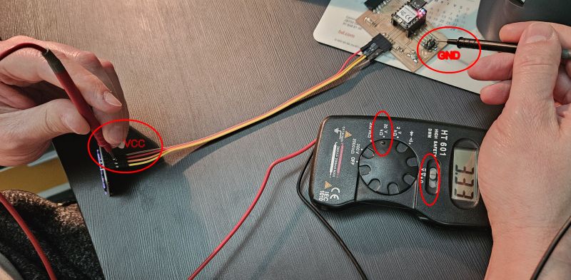
We recall that voltage is measured while the circuit is operating, placing the multimeter probes in parallel with the device being measured. When the multimeter is set to voltage mode, its internal resistance prevents current from flowing through the meter. However, when measuring current, this protection does not exist.
Current is measured by placing the multimeter in series with the device while it is operating. Therefore, it is very important to remember that, in this case, the current flows directly through the multimeter itself. We must always ensure that the measurement range and connections are correctly configured for safety, because if the circulating current exceeds the limits of the multimeter, it can be damaged.
Normally, only the fuse would burn, but in the event of a short circuit, the entire device could be damaged.
For example, if we intend to measure voltage and connect the probes in parallel, but forget to change the settings and leave the multimeter in current mode, we will create a short circuit, potentially damaging both the multimeter and the circuit itself.
VOLTAGE MEASUREMENT
CURRENT MEASUREMENT
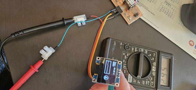
Therefore, the power consumption of the display is: 3.33 V × 0.00562 A = 18.7 mW
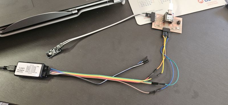
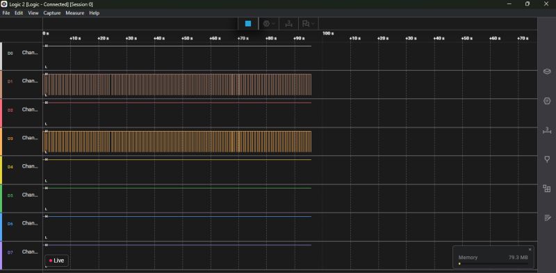
LOGIC ANALIZER
Finally, as an additional observation, we used the logic analyzer to monitor the SCL and SDA signals, observing how the spacing patterns between pulses change depending on what the display is showing at any given moment.
CONCLUSION
The conclusion of this assignment is that the XIAO RP2040 controller allows us to operate perfectly with multiple inputs and outputs, enabling us to run increasingly complex code without noticing any kind of overload. I am confident that we can achieve many more functionalities with this controller.